EP0828037B1 - Front face finishing profile for balconies or terraces covered with tiles - Google Patents
Front face finishing profile for balconies or terraces covered with tiles Download PDFInfo
- Publication number
- EP0828037B1 EP0828037B1 EP97111261A EP97111261A EP0828037B1 EP 0828037 B1 EP0828037 B1 EP 0828037B1 EP 97111261 A EP97111261 A EP 97111261A EP 97111261 A EP97111261 A EP 97111261A EP 0828037 B1 EP0828037 B1 EP 0828037B1
- Authority
- EP
- European Patent Office
- Prior art keywords
- profile
- balcony
- finishing profile
- finishing
- terrace
- Prior art date
- Legal status (The legal status is an assumption and is not a legal conclusion. Google has not performed a legal analysis and makes no representation as to the accuracy of the status listed.)
- Expired - Lifetime
Links
Images


Classifications
-
- E—FIXED CONSTRUCTIONS
- E04—BUILDING
- E04F—FINISHING WORK ON BUILDINGS, e.g. STAIRS, FLOORS
- E04F19/00—Other details of constructional parts for finishing work on buildings
- E04F19/02—Borders; Finishing strips, e.g. beadings; Light coves
-
- E—FIXED CONSTRUCTIONS
- E04—BUILDING
- E04D—ROOF COVERINGS; SKY-LIGHTS; GUTTERS; ROOF-WORKING TOOLS
- E04D13/00—Special arrangements or devices in connection with roof coverings; Protection against birds; Roof drainage; Sky-lights
- E04D13/04—Roof drainage; Drainage fittings in flat roofs, balconies or the like
- E04D13/0404—Drainage on the roof surface
- E04D13/0459—Drainage borders, e.g. dripping edges, gravel stops or dispersers
-
- E—FIXED CONSTRUCTIONS
- E04—BUILDING
- E04F—FINISHING WORK ON BUILDINGS, e.g. STAIRS, FLOORS
- E04F19/00—Other details of constructional parts for finishing work on buildings
- E04F19/02—Borders; Finishing strips, e.g. beadings; Light coves
- E04F19/06—Borders; Finishing strips, e.g. beadings; Light coves specially designed for securing panels or masking the edges of wall- or floor-covering elements
- E04F19/061—Borders; Finishing strips, e.g. beadings; Light coves specially designed for securing panels or masking the edges of wall- or floor-covering elements used to finish off an edge or corner of a wall or floor covering area
-
- E—FIXED CONSTRUCTIONS
- E04—BUILDING
- E04D—ROOF COVERINGS; SKY-LIGHTS; GUTTERS; ROOF-WORKING TOOLS
- E04D13/00—Special arrangements or devices in connection with roof coverings; Protection against birds; Roof drainage; Sky-lights
- E04D13/04—Roof drainage; Drainage fittings in flat roofs, balconies or the like
- E04D13/0404—Drainage on the roof surface
- E04D13/0459—Drainage borders, e.g. dripping edges, gravel stops or dispersers
- E04D2013/0468—Drip edges
Landscapes
- Engineering & Computer Science (AREA)
- Architecture (AREA)
- Civil Engineering (AREA)
- Structural Engineering (AREA)
- Floor Finish (AREA)
- Absorbent Articles And Supports Therefor (AREA)
- Materials For Medical Uses (AREA)
- Orthopedics, Nursing, And Contraception (AREA)
- Steps, Ramps, And Handrails (AREA)
- Building Environments (AREA)
Abstract
Description
Die Erfindung betrifft ein Abschlußprofil für mit Fliesen verlegte Balkone, Terrassen o.dgl. mit einem Abdeckabschnitt zur Abdeckung zumindest eines Teils der freien Stirnflächen der unter den Fliesen befindlichen Schicht/en des Balkons, der Terrasse o.dgl., in dessen oberem Randbereich ein im wesentlichen ebenflächiger und in der bestimmungsgemäßen Montageposition horizontal verlaufender Verankerungsschenkel zur Verankerung des Abschlußprofils auf oder in einer unter den Fliesen befindlichen Schicht des Balkons, der Terrasse o.dgl.angesetzt ist, wobei an dem Abdeckabschnitt ein Einfassungsabschnitt zur Einfassung der freien Stirnseiten der im äußersten Randbereich des Balkons, der Terrasse o.dgl. verlegten Fliesen angesetzt ist und der Einfassungsabschnitt wenigstens eine Entwässerungsöffnung zur Ableitung zwischen dem Abschlußprofil und den Fliesen anfallenden Sickerwassers aufweist.The invention relates to a closure profile for tiles laid balconies, terraces or the like. with a cover section to cover at least part of the free one End faces of the layer under the tiles of the balcony, the terrace or the like, in its upper Edge region a substantially planar and in the intended mounting position horizontally extending Anchoring leg for anchoring the end profile on or in a layer under the tiles the balcony, the terrace or the like. is attached, being on the Cover portion a skirt portion for enclosing the free end faces of the outermost edge area of the balcony, the terrace or the like laid tiles is attached and the skirt portion has at least one drainage hole for the derivation between the final profile and Having the tiles accumulating leachate.
Solche Abschlußprofile sind bekannt, z.B. aus den deutschen
Gebrauchsmustern 90 04 119, 295 14 797 und 296 05 100 sowie
der deutschen Patentanmeldung 195 08 342. Sie dienen dazu,
eine oder mehrere Schichten eines Balkons, einer Terrasse
o.dgl., also z.B. einer Estrichschicht und/oder die Balkon-Tragplatte,
mittels des Abdeckabschnitts vor äußeren Witterungseinflüssen
zu schützen, wobei der Abdeckabschnitt sowohl
derart ausgebildet sein kann, daß nur unterhalb des
Verankerungsschenkels befindliche Schichten abgedeckt werden
(siehe z.B. DE 295 14 797 U1 oder DE 296 08 100 U1),
als auch derart, daß unterhalb und oberhalb des Verankerungsschenkels
gelegene Schichten zumindest teilweise abgedeckt
werden (siehe z.B. DE 90 04 119 U1 oder DE 195 08 342
A1). Der die unterhalb des Verankerungsschenkels vorgesehenen
Schichten abdeckende Teil des Abdeckabschnitts ist
zudem in der Regel so ausgebildet, daß die Durchtrocknung
der unterhalb des Verankerungsschenkels gelegenen Schichten
nicht behindert wird, wozu dieser Teil des Abdeckabschnitts
zumindest teilweise mit Abstand zu den abgedeckten Schichten
verläuft, so daß eine Luftzufuhr zu diesen Schichten
weiterhin möglich ist.Such termination profiles are known, e.g. from the
Problematisch ist jedoch bei allen bekannten Abschlußprofilen der Übergangsbereich zwischen dem jeweiligen Abschlußprofil und einem oberhalb des Abschlußprofils verlegten Fliesenbelag. Werden im Randbereich des Balkons, der Terrasse o.dgl. normale ebenflächige Fliesen verwendet und ist das Abschlußprofil derart ausgebildet, daß der Abdeckabschnitt nur unterhalb des Verankerungsschenkels liegende Schichten abdeckt, so entsteht beim Verlegen der Fliesen auf dem Abschlußprofil notwendigerweise eine zur Stirnseite des Balkons, der Terrasse o.dgl. hin offene Fuge zwischen Verankerungsschenkel und Fliese. Diese Fuge ist optisch und technisch gleichermaßen unbefriedigend. Wird sie mit einem Dichtstoff abgedichtet, so kann zwischen den Fliesen eindringendes Sickerwasser nicht nach vorn ablaufen, so daß es sich staut und zu Ausblühungen und/oder Frostschäden führen kann. Wird die Fuge mit dem üblichen wasserdurchlässigen Fliesenmörtel verfugt, so kann zwar Wasser austreten, dieses unterspült jedoch im Laufe der Zeit die Verfugung, so daß der Mörtel allmählich herausbricht und sich gegebenenfalls die vorderen Fliesen lösen können. Werden Abschlußprofile verwendet, deren Abdeckabschnitt auch oberhalb des Verankerungsschenkels gelegene Schichten des Balkons, der Terrasse o.dgl. abdeckt, so ist es zwar prinzipiell möglich, diesen nach oben weisenden Teil des Abdeckabschnitts derart zu verlängern, daß er auch den Fliesenbelag stirnseitig abdeckt, jedoch tritt dann wieder das Problem der Stauung von Sickerwasser auf.However, the problem is with all known end profiles the transitional area between the respective final profile and a laid above the final profile Tile covering. Be in the edge area of the balcony, the terrace or the like. normal planar tiles are used and is the end profile is formed such that the cover just below the anchoring leg Covering layers, so arises when laying the tiles on the final profile necessarily one to the front page the balcony, the terrace or the like. open gap between Anchoring legs and tile. This joint is optical and technically equally unsatisfactory. Will she be with one Sealant sealed, so can penetrate between the tiles Leachate does not drain to the front, so that it accumulates and leads to efflorescence and / or frost damage can. Will the joint with the usual water-permeable Tile grout grouted, so while water can escape, this However, in the course of time, flushes the joint, so that the mortar gradually breaks out and optionally can dissolve the front tiles. Be final profiles used, the cover also above the Anchoring leg located layers of the balcony, the Terrace or similar although it is possible in principle, this upwardly facing part of the cover extend so that he also the tiled surface frontally covers, but then again the problem of Stagnation of leachate on.
Zur Vermeidung dieser Probleme werden daher im Randbereich des Balkons, der Terrasse o.dgl. keine ebenflächigen Fliesen, sondern sog. "Winkelplatten" verwendet, bei denen es sich quasi um L-förmig abgewinkelte Fliesen handelt. Diese Winkelplatten können dann so verlegt werden, daß der eine Schenkel wie eine normale Fliese parallel zum Boden des Balkons, der Terrasse o.dgl. verläuft, während der andere Schenkel im verlegten Zustand in der Regel nahezu senkrecht nach unten weist und somit zum einen eine Wasserableitkante für auf dem Balkon, der Terrasse o.dgl. anfallendes Wasser bildet, zum anderen aber auch die direkt unterhalb der Fliesen gelegenen Schichten vor äußeren Witterungseinflüssen schützt. Diese keramischen Winkelplatten sind jedoch äußerst herstellungsaufwendig und damit teuer. Sie werden in der Regel nur zu solchen Fliesen passend angeboten, die im Strangpreßverfahren hergestellt sind. Zu trocken gepreßten Fliesen finden sich nur im Ausnahmefall passende Winkelplatten.To avoid these problems are therefore in the edge area the balcony, the terrace or the like. no flat tiles, but so-called "angle plates" used in which it is virtually about L-shaped angled tiles. These Angle plates can then be laid so that one Thighs like a normal tile parallel to the bottom of the Balconies, the terrace or the like. runs while the other one Legs in the laid state usually almost vertical points down and thus on the one hand a Wasserableitkante for on the balcony, the terrace or similar. accumulating water forms, on the other hand, but also directly below the Tiled layers against external weather conditions protects. However, these ceramic angle plates are extremely expensive to manufacture and therefore expensive. you will be usually only suitable for those tiles that are suitable are produced by extrusion. Too dry pressed Tiles are only in exceptional cases matching angle plates.
Bei einem bekannten Abdeckprofil der eingangs erwähnten Art (DE 295 11 065 U1) ist an dem vorderen freien Ende des Verankerungsschenkels eine ebenflächige, sich in der bestimmungsgemäßen Montageposition an einem Balkon rechtwinklig und sich sowohl in Abwärtsrichtung vor die Stirnfläche der Balkon-Tragplatte als auch in Aufwärtsrichtung vor die Stirnfläche der äußeren Plattenreihe des Plattenbelags erstreckende, so genannte Abschlußleiste vorgesehen, wobei die Entwässerungsöffnung in dem oberhalb des Verankerungsschenkels liegenden, sich vor die Stirnfläche der Platten des Plattenbelags erstreckenden Abschnitt dieser Abschlußleiste vorgesehen sind. Eine schnelle, sichere und vollständige Entwässerung des durch den Plattenbelag auf die Abdichtung der Balkon-Tragplatte durchtretenden Sickerwassers ist hierbei nicht ohne weiteres gewährleistet, weil der Abfluß des Sickerwassers durch die oberhalb des Verankerungsschenkels vorgesehene Entwässerungsöffnung nicht optimal ist und sich im Laufe der Zeit durch angeschwemmte Verunreinigungen noch verschlechtern kann.In a known cover profile of the type mentioned (DE 295 11 065 U1) is at the front free end of the anchoring leg a planar, in the intended Mounting position on a balcony at right angles and facing both downwards in front of the face of the Balcony support plate as well as in the upward direction in front of the End face of the outer plate row of the plate covering extending, so-called terminal strip provided, wherein the drainage opening in the above the anchoring leg lying in front of the end face of the plates the plate covering extending portion of this end strip are provided. A fast, safe and complete Drainage of the tiled surface on the Sealing the balcony support plate by passing leachate This is not guaranteed without further ado, because the drainage of the leachate through the above the anchoring leg intended drainage opening not optimal is and washed up over time Impurities can still worsen.
Aus der DE 90 07 152 U1 ist ein von einer mehrfach abgekanteten Winkelleiste aus Aluminium gebildetes Balkon-Abschlussprofil bekannt, welches ein bis vor die äußere Stirnfläche der Randfliesen eines Balkons hochgezogenen Abdeckschenkel aufweist, an dessen unterem, noch geringfügig bis unter die Oberseite der Balkon-Tragplatte geführtem Randbereich durch zwei voneinander beabstandete parallele umgekantete streifenförmige Bereiche eine Wasserrinne gebildet ist, aus welcher aus dem Balkonbelag zutretendes Wasser durch Öffnungen in dem den Boden der Wasserrinne bildenden umgekanteten Bereich abfließen kann. Eine Abdeckung der Stirnfläche der Tragplatte des Balkons gegen Witterungseinflüsse wird mit dieser Wasserrinne aber nicht oder allenfalls im oberen Randbereich der Stirnfläche erzielt. Bei stärkerem, in Richtung zur Tragplatte gerichtetem Windanfall muss sogar damit gerechnet werden, daß aus den Öffnungen der Wasserrinne austretendes Wasser an die Stirnfläche der Tragplatte getrieben wird.From DE 90 07 152 U1 is one of a multiple folded Angle bar made of aluminum balcony profile known, one to the outside End face of the edge tiles of a balcony raised cover leg has, at the bottom, still slightly led to under the top of the balcony support plate Edge region by two spaced apart parallel umgekantete strip-shaped areas formed a gully is, from which from the balcony covering zutretendes Water through openings in the bottom of the gully can flow away forming edged area. A cover the end face of the support plate of the balcony against But the weather does not change with this gully or possibly achieved in the upper edge region of the end face. With stronger, directed towards the support plate Windfall must even be expected that out the openings of the gully escaping water to the End face of the support plate is driven.
Der Erfindung liegt daher die Aufgabe zugrunde, ein Abschlußprofil für mit Fliesen belegte Balkone, Terrassen o.dgl. anzugeben, welches unter Vermeidung der genannten Nachteile nicht nur eine eine optisch und technisch befriedigende Einfassung der Randfliesen derart ermöglicht, daß die äußeren Stirnseiten der Fliesen und die darunter liegenden Beläge vor äußeren Witterungseinflüssen geschützt sind, sondern auch sicherstellt, daß zwischen den Fliesen eindringendes Sickerwasser problemlos und vollständig abgeführt wird.The invention is therefore based on the object, a closure profile for tiled balconies, terraces or the like. specify which, while avoiding said Disadvantages not only a visually and technically satisfactory Enclosing the edge tiles allows such that the outer faces of the tiles and the underlying ones Coverings protected from external weather conditions are, but also ensures that between the tiles penetrating leachate easily and completely dissipated becomes.
Ausgehend von einem Abschlußprofil der eingangs erwähnten Art wird diese Aufgabe erfindungsgemäß dadurch gelöst, daß der Einfassungsabschnitt einen im bestimmungsgemäßen Montagezustand des Abschlußprofils vom oberen Rand des Abdeckabschnitts in entgegengesezter Richtung zum Verlängerungsschenkel über vom Abdeckabschnitt abgedeckte Schichten des Balkons, der Terrasse o.dgl. nach außen vortretenden, schräg abwärts geneigten Profilstreifen sowie einen an dessen verankerungsschenkelabgewandtem Rand und somit gegenüber dem Rand des Balkons, der Terrasse o.dgl. nach außen versetzt angesetzten, im Wesentlichen senkrecht in Aufwärtsrichtung weisenden Fliesenabdeckschenkel zur Abdeckung der äußeren Fliesen-Stirnseiten des FliesenBelags aufweist, und daß die Entwässerungsöffnungen in dem über den Abdeckabschnitt vortretenden, Profilstreifen vorgesehen ist bzw. sind. Die Entwässerungsöffnungen sind dabei in einem vor Schlagregen geschützten und praktisch nicht einsehbaren Teil des Abschlußprofils angeordnet, so daß auch bei Wind und Regen kein Wasser durch die Entwässerungsöffnungen hinein oder anfallendes Sickerwasser unter den Fliesen zurückgedrückt werden kann. Starting from a final profile of the aforementioned Kind this object is achieved in that the edging portion in the intended mounting state the final profile of the upper edge of the cover in the opposite direction to the extension leg over covered by the cover portion layers of the Balconies, the terrace or the like. outwardly obliquely downwardly inclined profile strip and an its anchoring leg facing away from the edge and thus opposite the edge of the balcony, the terrace or the like. to placed externally offset, substantially perpendicular in Upward facing tile cover legs to Covering the exterior tile front ends of tile flooring and that the drainage openings in the over the cover section vortretenden, profile strips is provided or are. The drainage holes are doing so in a protected from driving rain and practical not visible part of the final profile arranged so that even in wind and rain no water through the Drainage holes or accumulating leachate can be pushed back under the tiles.
Bei einer zweckmäßigen Ausgestaltung der Erfindung sind mehrere Entwässerungsöffnungen in den vortretenden Profilstreifen vorgesehen, wobei vorzugsweise jeweils benachbarte Entwässerungsöffnungen durch eine rinnenartige Vertiefung in den vortretenden Profilstreifen miteinander verbunden sind. Dies erlaubt bei besonders starkem Anfall von Sickerwasser oder dann, wenn z.B. durch Ablagerungen der Austritt von Flüssigkeit durch eine Entwässerungsöffnung behindert sein sollte, die Weiterleitung von Sickerwasser an benachbarte Entwässerungsöffnungen.In an expedient embodiment of the invention several drainage holes in the protruding profile strips provided, preferably each adjacent Drainage holes through a groove-like depression connected to each other in the protruding profile strips are. This allows for particularly strong seizure of leachate or then if e.g. due to deposits of the outlet obstructed by fluid through a drainage opening should be, the forwarding of leachate to neighboring Drainage holes.
An der im bestimmungsgemäßen Montagezustand unteren Kante des Fliesenabdeckschenkels und/oder an der dem Fliesenabdeckschenkel abgewandten Seite der Entwässerungsöffnung/en kann eine Tropfnase vorgesehen werden, welche das Abreißen anfallender Wassertropfen begünstigt, so daß diese nicht an dem Profil hängenbleiben, dort verdunsten und so zu Ablagerungen führen.At the lower edge in the intended mounting state the Tile Covering Leg and / or the Tile Cover Leg opposite side of the drainage opening / s a drip nose can be provided which the Tearing off accumulating drops of water favored, so that these Do not get stuck on the profile, evaporate there and so on lead to deposits.
Bei besonders großen Balkonen oder Terrassen kann es notwendig werden, zwei oder mehr Abschlußprofile auf Stoß miteinander zu verlegen. Vorteilhaft werden dazu an jedem Abschlußprofil Ausrichtmittel, insbesondere eine sich in Profillängsrichtung erstreckende nutartige Vertiefung mit verengter Mündung, zum fluchtenden Ausrichten zweier Abschlußprofile vorgesehen. In eine solche nutartige Vertiefung kann dann bei der Verlegung zweier Abschlußprofile auf Stoß ein Verbindungsriegel mit zu der nutartigen Vertiefung zumindest partiell komplementären Querschnitt derart eingeschoben werden, daß er sich zum Teil in dem einen und zum Teil in dem anderen Profil befindet und so die beiden Profile fluchtend zueinander ausrichtet. Anstelle der nutartigen Vertiefung können jedoch auch andere Ausrichtmittel, z.B. Steckverbindungsmittel (z.B. mit vorspringenden Bolzen an dem einen Profil und entsprechenden Aufnahmen an dem anderen Profil) vorgesehen werden.For very large balconies or terraces may be necessary be, two or more final profiles on impact with each other relocate. Be beneficial to each end profile Alignment, in particular a profile in the longitudinal direction extending groove-like depression with narrowed Mouth, for aligning two closing profiles intended. In such a groove-like depression can then when laying two end profiles on impact a connecting bolt with to the groove-like recess at least partially complementary cross section inserted in such a way that he is partly in the one and the Part is in the other profile and so are the two profiles aligns with each other in alignment. Instead of the groove-like Deepening, however, can also be other alignment means, e.g. Connector means (e.g., with protruding bolts on the one profile and corresponding shots on the other Profile) are provided.
Zweckmäßigerweise wird das Abschlußprofil derart ausgebildet, daß an dem Abdeckabschnitt Mittel zur Befestigung eines oder mehrerer weiterer Profilteile vorgesehen sind. Dies erlaubt es vorteilhaft, nachträglich - also nach dem Einbau des Abschlußprofilsystems - weitere Profilteile anzubringen und gegebenenfalls auszuwechseln. So kann z.B. bei Balkonen mit außergewöhnlich dickem Boden an dem Abschlußprofil ein das Profil nach unten verlängerndes Verblendprofil befestigt, also z.B. bei entsprechender Ausgestaltung der Befestigungsmittel eingehängt werden. Oftmals stellt sich auch erst im Laufe der Zeit heraus, daß der Anfall von Wasser auf dem Balkon doch problematisch ist, wobei dann vorteilhaft an dem Abschlußprofil ein Kanal zur Ableitung auf dem Balkon anfallenden Wassers befestigt werden kann. Schließlich können auch sogenannte Eckverbinder an dem Profil befestigt werden, bei denen es sich praktisch um kurze, unter einem Gehrungsstoß zusammentreffende und miteinander fest verbundene Abschlußprofile handelt, die in den Fällen, in denen nicht nur z.B. die Frontseite eines Balkons, einer Terrasse o.dgl., sondern auch die beiden Seitenflächen mit Abschlußprofilen versehen werden sollen, vorgesehen werden können.Conveniently, the end profile is formed such that on the cover portion means for fixing a or several other profile parts are provided. This allows advantageous later - ie after the Installation of the end profile system - to install further profile parts and replace if necessary. Thus, e.g. for balconies with exceptionally thick floor at the end profile a profile profile extending downwards attached, e.g. with appropriate design the fastener are hung. often It only turns out in the course of time that the seizure of water on the balcony is problematic, though then advantageously at the end profile a channel for Drain on the balcony accumulating water be attached can. Finally, so-called corner connectors attached to the profile where it is convenient for short, under a miter stroke coinciding and firmly connected to each other end profiles, which in in cases where not only e.g. the front of a Balconies, a terrace or the like, but also the two Side surfaces should be provided with end profiles, can be provided.
Das Abschlußprofil eignet sich sowohl zur sog. Dickbettverlegung, bei welcher auf den Verankerungsschenkel eine in der Regel einige Millimeter bis Zentimeter starke Schicht fließfähigen Materials, z.B. Estrich oder ähnliches, aufgebracht wird, als auch zur in der Regel im Rahmen von Renovierungsarbeiten angewandten Dünnbettverlegung, bei der der Verankerungsschenkel des Profils auf bereits bestehende relativ dicke Schichten des Balkons aufgesetzt und nur noch eine dünne Schicht, z.B. eine Schicht Klebemörtel, auf den Verankerungsschenkel aufgebracht wird. Speziell für die Dickbettverlegung kann jedoch in vorteilhafter Weiterbildung der Erfindung an dem Abdeckabschnitt ein weiterer, etwa parallel zu dem Verankerungsschenkel verlaufender und in dieselbe Richtung wie der Verankerungsschenkel weisender, jedoch im bestimmungsgemäßen Montagezustand oberhalb des Verankerungsschenkels verlaufender Profilstreifen angesetzt sein. Dieser Profilstreifen ermöglicht zum einen die besonders gute Verankerung des Profils in dem fließfähigen Material und bildet zum anderen eine Basis für eine darauf aufzuklebende Abdichtfolie.The final profile is suitable both for so-called thick bed laying, in which on the anchoring leg a in usually a few millimeters to centimeters thick layer flowable material, e.g. Screed or similar, applied is, as well as usually in the context of renovations applied thin bed laying, in which the Anchoring leg of the profile on existing relatively thick layers of the balcony put on and only a thin layer, e.g. a layer of adhesive mortar on the Anchoring leg is applied. Especially for the Thick bed installation, however, can in an advantageous development the invention on the cover section another, approximately parallel to the anchoring leg extending and pointing in the same direction as the anchoring leg, however, in the intended mounting state above attached to the anchoring leg extending profile strip be. This profile strip allows for a the particularly good anchoring of the profile in the flowable Material and forms on the other a basis for a to be stuck on sealing film.
Sind - wie oben bereits erwähnt - zwei Profile auf Stoß miteinander zu verlegen, so kann vorteilhaft an den Profilen jeweils eine Aufnahme zur Aufnahme eines zu der Aufnahme zumindest partiell komplementären Eingriffabschnitts eines Abdichtclips vorgesehen werden. Selbstverständlich ist es auch möglich, den Abdichtclip selbst mit einer solchen Aufnahme zu versehen und entsprechende Eingriffsabschnitte an den Profilen anzuordnen. In beiden Fällen kann jedenfalls ein solcher z.B. aus Aluminium oder Kunststoff geformter Abdichtclip nach dem Verlegen der Profile zur Abdichtung der problematischen Stoßstelle auf den Profilen befestigt, z.B. aufgerastet werden.Are - as mentioned above - two profiles on impact to lay each other, so can be beneficial to the profiles in each case one receptacle for receiving one to the recording at least partially complementary engagement portion of a Sealing clips are provided. Of course it is It is also possible, the Abdichtclip itself with such To be provided recording and appropriate engagement sections to arrange on the profiles. In both cases, anyway such as e.g. made of aluminum or plastic molded sealing clip after laying the profiles for sealing the problematic joint on the profiles attached, e.g. be snapped.
Ist an dem Abschlußprofil ein über unterhalb des Verankerungsschenkels befindliche Schichten des Balkons, der Terrasse o.dgl. nach außen vortretende Profilstreifen vorgesehen, so wird die Aufnahme bzw. der Eingriffsabschnitt vorzugsweise an der dem Abdeckabschnitt zugewandten Unterseite dieses vortretenden Profilstreifens angeordnet, und zwar derart, daß die Aufnahme bzw. der Eingriffsabschnitt zwischen den Entwässerungsöffnungen und dem Abdeckabschnitt gelegen ist. Diese Anordnung gewährleistet, daß auch an der Stoßstelle zweier Abschlußprofile kein Wasser hinter die Abdeckabschnitte gelangen kann, wobei der vortretende Profilstreifen vorteilhaft den oberen Übergangsbereich von Abdichtclip und Abdeckabschnitt dachartig überragt. Is at the end profile over one below the anchoring leg located layers of the balcony, the terrace or the like. provided outwardly projecting profile strips, so the receptacle or the engagement portion is preferably on the underside facing the cover section arranged this vortretenden profile strip, and indeed such that the receptacle or the engagement section between the drainage holes and the cover section is located. This arrangement ensures that also at the Joint of two end profiles no water behind the Cover sections can get, wherein the protruding profile strip Advantageously, the upper transition region of Abdichtclip and roof overhanging roof portion.
Weitere Einzelheiten und Vorteile ergeben sich aus den rein beispielhaft einige der möglichen Ausführungsformen der Erfindung zeigenden Zeichnungen und deren nachfolgender Beschreibung. Es zeigen:
- Fig. 1
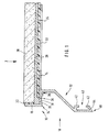
- einen Schnitt rechtwinklig zur Längserstreckung eines Abschlußprofiles und einer darauf verlegten Fliese,
- Fig. 2
- das Abschlußprofil gemäß Fig. 1 in der
in Richtung des
Pfeiles 2 gesehenen Draufsicht, jedoch ohne die Fliese oder sonstige Beläge, - Fig. 3
- ein Abschlußprofil in Seitenansicht und einen Schnitt durch einen an dem Abschlußprofil befestigten Abdichtclip,
- Fig. 4 u. 5
- Detailausschnitte des Abschlußprofiles und des Abdichtclips gemäß Fig. 3 in vergrößertem Maßstab,
- Fig. 6
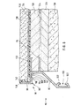
- einen Schnitt durch ein speziell zur Verlegung im Dickbett ausgebildetes Abschlußprofil einschließlich Fliese, Estrich und Balkon-Tragplatte, und
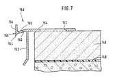
- Fig. 7
- einen Schnitt rechtwinklig zur Längserstreckung eines weiteren Ausführungsbeispiels eines auf Estrich verlegten erfindungsgemäßen Abschlußprofils.
- Fig. 1
- a section at right angles to the longitudinal extent of a final profile and a tile laid thereon,
- Fig. 2
- 1 in the direction of the
arrow 2 seen top view, but without the tile or other coverings, - Fig. 3
- a closure profile in side view and a section through a sealing clip attached to the end profile,
- Fig. 4 u. 5
- Detail sections of the final profile and the Abdichtclips of FIG. 3 on an enlarged scale,
- Fig. 6
- a section through a specially designed for installation in thick bed end profile including tile, screed and balcony support plate, and
- Fig. 7
- a section at right angles to the longitudinal extent of another embodiment of a laid on screed end profile according to the invention.
In der Fig. 1 ist ein in seiner Gesamtheit mit 10 bezeichnetes
Abschlußprofil gezeigt, das einen Abdeckabschnitt 12,
einen Verankerungsschenkel 14 und einen Einfassungsabschnitt
16 aufweist. Der Einfassungsabschnitt 16 besteht
aus einem im bestimmungsgemäßen Einbauzustand im wesentlichen
senkrechten Fliesenabdeckschenkel 18 und einem sich
bei diesem Ausführungsbeispiel in Verlängerung des Verankerungsschenkels
14 befindenden und über hier nicht weiter
gezeigte, unterhalb des Verankerungsschenkels befindliche
Schichten eines Balkons, einer Terrasse o.dgl., wie z.B.
eine Estrichschicht und eine Balkon-Tragplatte, nach außen
vortretenden Profilstreifen 20.In Fig. 1 is a denoted in its entirety by 10
End profile shown having a
In dem Verankerungsschenkel 14 sind - wie insbesondere in
der Fig. 2, die eine Draufsicht auf das Abschlußprofil 10
gesehen in Richtung des Pfeiles 2 in Fig. 1, jedoch ohne
die sonstigen in Fig. 1 gezeigten Bauteile und Belagschichten
zeigt, gut zu erkennen ist - eine Reihe von Durchbrechungen
22 vorgesehen, welche einerseits die Einsparung einer
erheblichen Menge an Profilmaterial ermöglichen und andererseits
eine besonders feste, nämlich formschlüssige
Verankerung des Abschlußprofiles in einer zunächst fließfähigen
und dann aushärtenden Schicht des Balkones, der Terrasse
o.dgl. wie in Fig. 6 gezeigt erlauben.In the anchoring
Auf den Verankerungsschenkel 18 ist eine dünne, hier nur
teilweise gezeigte Abdichtfolie 24 aufgeklebt, die sich unterhalb
des gesamten Fliesenbelags erstreckt und das Eindringen
von zwischen den Fliesen durchtretender Feuchtigkeit
in die unterhalb der Abdichtfolie 24 gelegenen Belagschichten
des Balkons, der Terrasse o.dgl. verhindert. Abschlußprofilseitig
endet die Abdichtfolie 24 vor den im
vortretenden Profilstreifen 20 vorgesehenen Entwässerungsöffnungen
26. Auf die Abdichtfolie 24 ist ein wasserdurchlässiger
Fliesenkleber oder Klebemörtel 28 aufgebracht,
mittels welchem die Fliesen 30, von denen in der Figur nur
eine teilweise gezeigt ist, auf dem Balkon, der Terrasse
o.dgl. befestigt werden. Zwischen dem Fliesenabdeckschenkel
18 und den diesem Schenkel zugewandten Stirnseiten der
Fliesen 30 ist eine Abdichtung 32, z.B. aus Silikon, vorgesehen.On the anchoring
An der Unterkante des Fliesenabdeckschenkels 18 ist eine
Tropfnase 34 angeformt; eine weitere Tropfnase 36 ist an
dem vortretenden Profilstreifen 20 in Richtung auf den Abdeckabschnitt
12 gesehen unmittelbar hinter jeder Entwässerungsöffnung
26 vorgesehen. Beide Tropfnasen 34 und 36 begünstigen
das Abreißen anfallender Wassertropfen und verhindern
auch bei stärkeren Winden, daß Wasser in Richtung
auf die hier nicht gezeigten, von dem Abdeckabschnitt 12
abgedeckten Schichten des Balkons, der Terrasse o.dgl. getrieben
wird. An der Unterseite des vortretenden Profilstreifens
20 ist ferner eine Aufnahme 38 gebildet, in die
ein entsprechend geformter Eingriffsabschnitt eines an der
Stoßstelle zweier Abschlußprofile aufrastbaren Abdichtclips
eingreifen kann, wie später im Zusammenhang mit den Figuren
3 bis 5 noch näher erläutert wird.At the lower edge of
Im unteren rückwärtigen Bereich des Abdeckabschnitts 12 ist
eine an sich bekannte nutartige Vertiefung 40 mit verengter
Mündung vorgesehen, die von zwei am Abdeckabschnitt 12 angeformten
rippenartigen Streifenabschnitten 42 gebildet
wird. In eine solche nutartige Vertiefung lassen sich
einerseits weitere Profilteile, wie z.B. eine den Abdeckabschnitt
12 nach unten verlängernde Frontblende oder ein
Kanal zur Ableitung von Flüssigkeiten einhängen oder einschieben,
zum anderen können an der Stoßstelle zweier z.B.
zum Abschluß eines sehr langen Balkones auf Stoß miteinander
zu verlegender Abschlußprofile relativ zur Länge der
Abschlußprofile kurze Verbindungsriegel in die nutartigen
Vertiefungen derart eingesteckt werden, daß sich jeweils
ein Riegel abschlußprofilübergreifend zum Teil in der nutartigen
Vertiefung des einen und zum Teil in der des anderen
Abschlußprofils befindet, wodurch die Abschlußprofile
vorteilhaft fluchtend miteinander ausgerichtet werden. In the lower rear region of the
Die Unterkante 44 des unteren rippenartigen Streifenabschnitts
42 ist vom Balkon, der Terrasse o.dgl. wegweisend
abgeschrägt, so daß der Abdeckabschnitt 12 vorteilhaft
in einer Abtropfkante 46 ausläuft.The
In dem Verankerungsschenkel 14 sind eine Reihe von Befestigungsbohrungen
48 vorgesehen, von denen in der Fig. 2 eine
gezeigt ist. Diese Befestigungsbohrungen 48 dienen zur Aufnahme
entsprechender Befestigungsschrauben, mittels welcher
sich das Abschlußprofil 10 sowohl bei Dünnbett- als auch
bei Dickbettverlegung auf einer darunterliegenden Schicht
des Balkons, der Terrasse o.dgl. fixieren läßt.In the anchoring
In den Fig. 3 bis 5 ist ein weiteres Ausführungsbeispiel
eines Abschlußprofils 50 in Seitenansicht gezeigt, das
ebenfalls aus einem Abdeckabschnitt 52, einem Verankerungsschenkel
54 sowie einem Einfassungsabschnitt 56 besteht.
Der Einfassungsabschnitt 56 wird von dem Fliesenabdeckschenkel
58 und dem Profilstreifen 60 gebildet. Die Oberkante
62 des Fliesenabdeckschenkels 58 ist von den hier
nicht gezeigten Fliesen wegweisend abgeschrägt, was das Ablaufen
von Wasser vorteilhaft begünstigt. In dem Profilstreifen
60 sind wiederum eine Reihe von hier nicht sichtbaren
und deshalb durch die gestrichelten Linien angedeuteten
Entwässerungsöffnungen 64 vorgesehen.In Figs. 3 to 5 is another embodiment
a
Wie insbesondere in der Fig. 4 gut zu erkennen ist, ist der
Profilstreifen 60 zu den Entwässerungsöffnungen 64 hin abgeschrägt,
so daß er in der bestimmungsgemäßen Einbaulage
von der durch die punktierte Linie 66 angedeuteten Ebene
des Verankerungsschenkels 54 nach unten abweicht. Anfallendes
Sickerwasser wird dadurch vorteilhaft stets zu den Entwässerungsöffnungen
64 geleitet. An der Unterseite des
Fliesenabdeckschenkels 58 und der Unterseite des Profilstreifens
60 sind - wie bereits im Zusammenhang mit dem in
Fig. 1 gezeigten Abschlußprofil beschrieben - zwei Tropfnasen
68 und 70 angeformt. As can be clearly seen in particular in FIG. 4, the
Ebenfalls an der Unterseite des Profilstreifens 60 ist kurz
vor dem Abdeckabschnitt 52 ein hinterschnittener Vorsprung
72 zur Bildung einer Aufnahme für einen entsprechenden Eingriffsabschnitt
74 eines Abdichtclips 76 vorgesehen. Ein
solcher Abdichtclip 76 dient zur Abdichtung der in den Fällen
entstehenden Stoßkante, in denen zwei Abschlußprofile
auf Stoß miteinander verlegt werden. Wie oben bereits im
Zusammenhang mit der Fig. 1 erläutert, können zwei Abschlußprofile
z.B. mittels eines in die nutartige Vertiefung
80, die auch bei diesem Ausführungsbeispiel von zwei
rippenartigen Streifenabschnitten 82 gebildet wird, einschiebbaren
Verbindungsriegels miteinander ausgerichtet
werden. Die dabei entstehende Stoßkante der beiden Profile
kann dann vorteilhaft einfach mittels des aufrastbaren
Clips 76 abgedichtet werden, so daß an dieser Stoßkante
kein Wasser durchdringen und die von dem Abdeckabschnitt 52
abgedeckten Schichten des Balkons, der Terrasse o.dgl.
durchfeuchten kann. Dazu wird der obere Eingriffsabschnitt
74 des Clips 76 in die mittels des hinterschnittenen Vorsprungs
72 am Abschlußprofil 50 gebildete Aufnahme eingeschoben
und sodann die untere, in Fig. 5 gut zu erkennende
Rastnase 84 des Clips über die Abtropfkante 86 des Abdeckabschnitts
52 gedrückt, so daß der Clip 76 schließlich
formschlüssig an den beiden Abdeckprofilen, deren Stoßkante
abzudichten ist, gehalten wird. In der Fig. 5 ist im übrigen
zu erkennen, daß an der unteren, abgeschrägten Innenseite
der nutartigen Vertiefung 80 eine Auflagekante 88
vorgesehen ist, welche es erlaubt, bei der Ausbildung der
nutartigen Vertiefung 80 Material zu sparen, gleichzeitig
aber auch eine gute Abstützung einzuhängender oder einzuschiebender
Profilteile gewährleistet.Also at the bottom of the
In der Fig. 6 ist ein speziell für die sogenannte Dickbettverlegung
ausgebildetes und in seiner Gesamtheit mit 90 bezeichnetes
Abschlußprofil gezeigt, das wiederum einen Abdeckabschnitt
92, einen Verankerungsschenkel 94 und einen
Einfassungsabschnitt 96 aufweist, der von einem Fliesenabdeckschenkel
98 und einem abgeschrägten Profilstreifen
100 gebildet wird. An der Unterseite des Profilstreifens
100 sind wiederum Tropfnasen 102 und 104 vorgesehen, die
sich einmal in Verlängerung des Fliesenabdeckschenkels 98
und einmal an der dem Abdeckabschnitt 92 zugewandten Seite
der auch bei diesem Ausführungsbeispiel im Profilstreifen
100 vorgesehenen Entwässerungsöffnungen 106, von denen hier
nur eine sichtbar ist, befinden. Ferner ist an dem Profilstreifen
100 ein hinterschnittener Vorsprung 108 zur Bildung
einer Aufnahme 110 für einen z.B. dem im Zusammenhang
mit den Fig. 3 bis 5 beschriebenen Abdichtclip 76 entsprechenden
Abdichtclip angeformt. Im unteren rückwärtigen Endbereich
des Abdeckabschnitts 52 ist eine den bereits beschriebenen
nutartigen Vertiefungen entsprechende nutartige
Vertiefung 120 mit verengter Mündung vorgesehen, die von
zwei rippenartigen Streifenabschnitten 122 gebildet wird.
Der Verankerungsschenkel 94 ist analog dem oberen im Zusammenhang
mit der Fig. 2 beschriebenen Verankerungsschenkel
mit einer Anzahl von hier durch die gestrichelten Linien
angedeuteten Durchbrechungen 124 vorgesehen, die bei der
Dickbettverlegung wie hier gezeigt von einem fließfähig
aufgebrachten und dann aushärtenden Estrich 126 durchsetzt
werden, so daß sich nach dem Aushärten des Estrichs 126
eine formschlüssige Verankerung des Abschlußprofiles ergibt.
Der Verankerungsschenkel 94 ist auf einen bereits
ausgehärteten, hier mit Gefälle vorgezogenen Estrich 128
aufgesetzt, der sich auf einer Beton-Tragplatte 130 befindet.
Es sei an dieser Stelle betont, daß natürlich anstelle
des Estrichs 128 auch andere Schichten unter dem Verankerungsschenkel
94 vorgesehen werden können, z.B. Drainagematten
oder -elemente.In Fig. 6 is a special for the so-called thick bed installation
trained and designated in its entirety by 90
End profile shown, in turn, a
Oberhalb des Verankerungsschenkels 94 ist ein im wesentlichen
parallel zu dem Verankerungsschenkel 94 verlaufender
und vom Abdeckabschnitt 92 gesehen aus in dieselbe Richtung
wie der Verankerungsschenkel 94 weisender, jedoch relativ
zu dem Verankerungsschenkel 94 kurzer Profilstreifen 132
vorgesehen, dessen Oberkante mit der Oberkante des Estrichs
126 bündig abschließt. Dieser zusätzliche Profilstreifen
132 gewährleistet zum einen eine besonders gute Verankerung
des Abschlußprofiles 90 in dem Estrich 126 und bildet zum
anderen eine Auflage- und Haltekante für eine auf den
Estrich 126 aufzuklebende Abdichtfolie 134. Bekannterweise
haften solche üblichen selbstklebenden Abdichtfolien 134
auf der Oberfläche des in der Regel metallischen, gegebenenfalls
auch aus Kunststoff bestehenden Abschlußprofils
besser als auf dem körnigen Estrich 126. Die Abdichtfolie
134 endet kurz vor den Entwässerungsöffnungen 106.Above the anchoring
Zur Verdeutlichung der Einbauweise eines solchen Abschlußprofiles
90 ist in den Figuren schließlich noch die nach
dem Verlegen der Abdichtfolie 134 aufzubringende Klebe-Mörtelschicht
136 gezeigt, in die dann die Fliesen, von denen
hier nur eine Fliese 138 sichtbar ist, eingebettet werden.
Eine zwischen Fliesenabdeckschenkel 98 und vorderer Fliesen-Stirnseite
140 verbleibende Fuge kann z.B. mit Silikon
142 ausgefüllt und abgedichtet werden.To illustrate the installation of such a
In der Fig. 7 ist ein auf einem Estrich 146, der auf einer
Abdichtfolie 148 aufgebracht wurde, verlegtes weiteres
Ausführungsbeispiel eines in seiner Gesamtheit mit 150
bezeichneten Abschlußprofiles gezeigt, das einen Abdeckabschnitt
152, einen Verankerungsschenkel 154 und einen
Einfassungsabschnitt 156 aufweist. Der Einfassungsabschnitt
156 besteht aus einem im bestimmungsgemäßen Einbauzustand
im wesentlichen senkrechten Fliesenabdeckschenkel 158 und
einem sich in Verlängerung des Verankerungsschenkels 154
befindenden und über die unterhalb des Verankerungsschenkels
vorgesehenen Schichten eines Balkons, im gezeigten
Beispiel also über die Estrichschicht 146 und die Abdichtfolie
148 nach außen vortretenden Profilstreifen 160. In Fig. 7 is a on a
In dem Verankerungsschenkel 154 sind - analog zu dem Fig. 1
und 2 gezeigten Ausführungsbeispiel - eine Reihe von
Durchbrechungen 162 vorgesehen, die nicht nur die Einsparung
einer erheblichen Menge an Profilmaterial ermöglichen,
sondern auch eine besonders feste, nämlich formschlüssige
Verankerung des Abschlußprofiles in der zunächst fließfähigen
und dann aushärtenden Estrichschicht 156 erlauben.In the anchoring
An der Unterkante des Fliesenabdeckschenkels 158 ist eine
Tropfnase 164 angeformt, die das Abreißen anfallender
Wassertropfen begünstigt. In dem vortretenden Profilstreifen
160 sind wiederum, wie bei den in den Fig. 1 bis 4 und
6 gezeigten Ausführungsformen, Entwässerungsöffnungen 166
vorgesehen. Das gezeigte Profil kann - wie auch die anderen
beschriebenen Ausführungsbeispiele - unter anderem vorteilhaft
einstückig im Strang-Preßverfahren hergestellt, aber
auch aus abgekanteten Profilen zusammengesetzt werden.At the lower edge of the
An dem freien Ende des Fliesenabdeckschenkels kann auch ein weiteres, z.B. in Richtung der Fliesen weisendes Profilteil angeformt sein. Erfindungswesentlich ist jedenfalls, daß das Abschlußprofil die vordere Stirnfläche der Fliesen abdeckt und gleichzeitig eine Entwässerung des zwischen den Fliesen anfallenden Sickerwassers ermöglicht.At the free end of Fliesenabdeckschenkels also can further, e.g. in the direction of the tiles facing profile part be formed. In any case, it is essential to the invention that the end profile covers the front face of the tiles and at the same time a drainage of between the Tile accumulating leachate allows.
Claims (8)
- Finishing profile (10; 50; 90; 150) for balconies, terraces or the like which are laid with flagstones, having a cover portion (12; 52; 92; 152) for covering at least a part of the course(s) of the balcony terrace or the like situated below the flagstones (30; 138), in the upper edge region of which there is attached a substantially flat anchoring flange (14; 54; 94; 154), which extends horizontally in the prescribed mounting position, for anchoring the finishing profile on or in a course (126, 128; 1) of the balcony, terrace or the like situated below the flagstones, wherein a skirting portion (16; 56; 96; 156) for skirting the free end faces (140) of the flagstones laid in the outermost edge region of the balcony, terrace or the like is attached to the cover portion (12; 52; 92; 152), and wherein the skirting portion (16; 56; 96; 156) has at least one drainage hole (26; 64; 106; 166) for draining off seepage water which accumulates between the finishing profile and the flagstones, characterised in that the skirting portion (16; 56; 96; 156) has a profile strip (20; 60; 100; 160) which, in the prescribed mounting state of the finishing profile, projects outwards and is inclined obliquely downwards from the upper edge of the cover portion (12; 52; 92; 152) in the opposite direction to the anchoring flange over courses of the balcony, terrace or the like which are covered by the cover portion, the said profile strip also having attached to its edge facing away from the anchoring flange and thus offset outwards relative to the edge of the balcony, terrace or the like a flagstone facing flange (18; 58; 98; 158) which is directed substantially vertically upwards for covering the outer front faces of the flagstones of the flagstone paving, and in that the drainage hole(s) (26; 64; 106; 166) is or are provided in the profile strip (20; 60; 100; 160) which projects over the cover portion (12; 52; 92; 152).
- Finishing profile as claimed in Claim 1, characterised in that a plurality of drainage holes are provided in the projecting profile strip, and that adjacent drainage holes in each case are connected to one another by a trough-like depression in the projecting profile strip.
- Finishing profile as claimed in Claim 1 or 2, characterised in that a drip lip (34, 36; 68, 70; 102, 104; 174) is formed on the lower edge of the flagstone facing flange (18, 58; 98; 158) in the prescribed mounting state and/or on the side of the drainage hole(s) (26; 64; 106; 166) facing away from the flagstone facing flange.
- Finishing profile as claimed in any one of Claims 1 to 3, characterised in that aligning means, particularly a groove-like depression (40; 80; 120) with a narrowed mouth, are provided on the finishing profile (10; 50; 90) for aligning two finishing profiles.
- Finishing profile as claimed in any one of Claims 1 to 4, characterised in that means (40, 38; 72; 80; 108, 110; 120) for fixing one or more further profile parts (76) are provided on the finishing profile (10; 50; 90).
- Finishing profile as claimed in any one of Claims 1 to 5, characterised in that a further profile strip (132) which extends approximately parallel to the anchoring flange (94) and points in the same direction as the anchoring flange, but extends above the anchoring flange in the prescribed state, is attached to the cover portion (92).
- Finishing profile as claimed in any one of Claims 1 to 6, characterised in that a receptacle (38; 110) is provided to receive an engaging portion (74) of a sealing clip (76) which is at least partially complementary to the receptacle.
- Finishing profile as claimed in Claim 7, characterised in that the receptacle (38; 110) is provided on the projecting profile strip (20; 100).
Applications Claiming Priority (2)
| Application Number | Priority Date | Filing Date | Title |
|---|---|---|---|
| DE19635852A DE19635852A1 (en) | 1996-09-04 | 1996-09-04 | End profile for tiled balconies, patios or the like. |
| DE19635852 | 1996-09-04 |
Publications (3)
| Publication Number | Publication Date |
|---|---|
| EP0828037A2 EP0828037A2 (en) | 1998-03-11 |
| EP0828037A3 EP0828037A3 (en) | 1998-12-30 |
| EP0828037B1 true EP0828037B1 (en) | 2005-06-29 |
Family
ID=7804588
Family Applications (1)
| Application Number | Title | Priority Date | Filing Date |
|---|---|---|---|
| EP97111261A Expired - Lifetime EP0828037B1 (en) | 1996-09-04 | 1997-07-04 | Front face finishing profile for balconies or terraces covered with tiles |
Country Status (3)
| Country | Link |
|---|---|
| EP (1) | EP0828037B1 (en) |
| AT (1) | ATE298827T1 (en) |
| DE (2) | DE19635852A1 (en) |
Cited By (2)
| Publication number | Priority date | Publication date | Assignee | Title |
|---|---|---|---|---|
| DE202007004298U1 (en) | 2007-03-13 | 2008-07-24 | Gutjahr, Walter | End profile arrangement for balconies, terraces and the like. with plate coverings |
| DE202007011416U1 (en) | 2007-08-16 | 2009-01-02 | Gutjahr, Walter | End profile arrangement for balconies, terraces and the like. |
Families Citing this family (13)
| Publication number | Priority date | Publication date | Assignee | Title |
|---|---|---|---|---|
| DE29912160U1 (en) * | 1999-07-05 | 2000-12-14 | Gutjahr Walter | End profile for balconies, patios or the like. |
| DE29921969U1 (en) * | 1999-12-14 | 2001-04-19 | Gutjahr Walter | Drainage system for balconies, patios and the like |
| DE10110308C1 (en) * | 2001-03-03 | 2002-10-17 | Reiner Laubach | Mounting for a rain gutter, at a balcony ledge, has a plate strip and an eave strip bent at right angles along its leading edge, with an inner hollow spacer profile to support the gutter and protect the balcony surfaces |
| DE502004011159D1 (en) * | 2004-09-14 | 2010-06-24 | Richard Malcher | Balcony end profile |
| DE102005036884A1 (en) * | 2005-08-05 | 2007-02-08 | Karl-Heinz Andratschke | Profile system for edging flat roofs, balcons, swimming pools and the like comprises two angle profiles which are joinable by means of at least one threaded bolt |
| DE102005061677A1 (en) * | 2005-12-21 | 2007-07-05 | Blanke Gmbh & Co.Kg, | End profile for the edge termination of balconies or terraces o. The like. With a drainage layer |
| AU2007200829B2 (en) * | 2006-04-28 | 2009-07-16 | Sean Herbert Klempert | Revedge |
| AT516982B1 (en) * | 2015-03-17 | 2017-01-15 | St-Profile Gmbh | Device for finishing a floor section having a slab or stone covering |
| EP3418471B1 (en) * | 2017-06-23 | 2020-04-22 | Croso International GmbH | Cover for a glass railing device |
| DE102017131240A1 (en) * | 2017-06-23 | 2018-12-27 | Croso International Gmbh | Cover for a glass railing device |
| IT201700094883A1 (en) * | 2017-08-22 | 2019-02-22 | Progress Profiles Spa | PROFILE PERFECTED FOR TERRACES AND BALCONIES |
| DE202020101640U1 (en) | 2020-03-26 | 2021-06-29 | Ardex Anlagen Gmbh | Closing facility |
| FR3128963B1 (en) * | 2021-11-10 | 2024-03-22 | Dani Alu | Cover profile for a section of a suspended construction element, with stop for pouring a liquid waterproofing system |
Family Cites Families (13)
| Publication number | Priority date | Publication date | Assignee | Title |
|---|---|---|---|---|
| FR1322714A (en) * | 1962-05-23 | 1963-03-29 | Edging for roof coverings | |
| DE2115629A1 (en) * | 1971-03-31 | 1972-10-12 | Mainz & Mauersberger, 4600 Dort mund | Roof end profile with horizontal fastening web |
| DE2243010A1 (en) * | 1972-09-01 | 1974-03-14 | Uhl Kg Geb | HOLDER FOR ROOF PANELING |
| DE9004119U1 (en) * | 1990-04-09 | 1990-06-13 | Gutjahr, Walter, 6101 Bickenbach, De | |
| DE9007152U1 (en) * | 1990-06-28 | 1990-09-06 | Templin, Guenter, 7990 Friedrichshafen, De | |
| CH687033A5 (en) * | 1993-07-07 | 1996-08-30 | Werner Nill | Edge profile for a roof edge of a building. |
| EP0709530B1 (en) * | 1994-10-31 | 1999-08-25 | Walter Gutjahr | End profile for balconies, terrasses and the like and method for laying the same |
| DE4443634A1 (en) * | 1994-12-08 | 1996-06-13 | Walter Gutjahr | Front wall end profile for balconies, patios and. the like |
| DE19508342C2 (en) * | 1995-02-03 | 2001-11-08 | Walter Gutjahr | Drainage system for balconies |
| DE29514797U1 (en) * | 1995-02-03 | 1996-06-05 | Gutjahr Walter | End profile system for balconies, patios and the like. |
| DE29504990U1 (en) * | 1995-03-24 | 1995-05-18 | Muenkel Rudolf | Eaves and facing profile element for balcony and terrace base plates |
| DE29511065U1 (en) * | 1995-07-07 | 1995-11-30 | Adolf Hausmann Fa | End profile for parts of the building |
| DE29606490U1 (en) * | 1996-04-10 | 1996-07-04 | Schlueter Systems Gmbh | End profile to limit balcony or terrace coverings |
-
1996
- 1996-09-04 DE DE19635852A patent/DE19635852A1/en not_active Withdrawn
-
1997
- 1997-07-04 EP EP97111261A patent/EP0828037B1/en not_active Expired - Lifetime
- 1997-07-04 AT AT97111261T patent/ATE298827T1/en active
- 1997-07-04 DE DE59712358T patent/DE59712358D1/en not_active Expired - Lifetime
Cited By (4)
| Publication number | Priority date | Publication date | Assignee | Title |
|---|---|---|---|---|
| DE202007004298U1 (en) | 2007-03-13 | 2008-07-24 | Gutjahr, Walter | End profile arrangement for balconies, terraces and the like. with plate coverings |
| EP1970498A2 (en) | 2007-03-13 | 2008-09-17 | Walter Gutjahr | End profile assembly for balconies, terraces and the like with tiles |
| DE202007011416U1 (en) | 2007-08-16 | 2009-01-02 | Gutjahr, Walter | End profile arrangement for balconies, terraces and the like. |
| EP2025827A1 (en) | 2007-08-16 | 2009-02-18 | Walter Gutjahr | End profile assembly for balconies, patios and the like |
Also Published As
| Publication number | Publication date |
|---|---|
| EP0828037A3 (en) | 1998-12-30 |
| DE59712358D1 (en) | 2005-08-04 |
| DE19635852A1 (en) | 1998-03-05 |
| EP0828037A2 (en) | 1998-03-11 |
| ATE298827T1 (en) | 2005-07-15 |
Similar Documents
| Publication | Publication Date | Title |
|---|---|---|
| EP0828037B1 (en) | Front face finishing profile for balconies or terraces covered with tiles | |
| EP1490565B1 (en) | Laying system for floor tiles | |
| EP2025827A1 (en) | End profile assembly for balconies, patios and the like | |
| EP0725194B1 (en) | Drainage device for balconies | |
| DE202005001609U1 (en) | Drainage channel for protecting e.g. balcony doors or windows, has system of interlocking box side walls, sliding parts and lifting parts for altering channel height | |
| CH701903B1 (en) | Fairing and drainage element for the faces of components such as balcony slabs, patios, walkways, flat roofs. | |
| DE19508342C2 (en) | Drainage system for balconies | |
| EP2527763A2 (en) | Cladding system for cladding the external surface of a building | |
| AT511661B1 (en) | CONNECTION ASSEMBLY OF SIDE-GROUNDED FLOOR OR WALL BOARD | |
| DE202004004107U1 (en) | Covering consisting of individual plates made of mineral material | |
| DE3634116A1 (en) | Sealing arrangement for structures | |
| DE19612505A1 (en) | Dewatering system for balcony with breastwork | |
| EP1970498B1 (en) | End profile assembly for balconies, terraces and the like with tiles | |
| EP1635007B1 (en) | Balcony edge profile | |
| EP0709530B1 (en) | End profile for balconies, terrasses and the like and method for laying the same | |
| DE202005020089U1 (en) | End section for e.g. balcony has opening on upper part of cover side, and into which edge of coating material is inserted | |
| AT8627U1 (en) | MOUNT FOR A ROOF | |
| DE10201528C1 (en) | Roof hip connector board, between the lower edge of a hip tile and the roof covering board, is a projection of the covering board surface with a wedge projection on the upper side towards the roof hip | |
| DE102007017612A1 (en) | Frame for a balcony or a terrace and method for its production | |
| AT523739B1 (en) | Mounting profile for mounting an outer window sill | |
| DE3626074C2 (en) | ||
| EP1625266A1 (en) | Cover for an area of balconies, floors, roofs, or facades | |
| EP0826849A2 (en) | Front face finishing profile system for balconies or similar | |
| DE4443492C2 (en) | End wall end profile for balconies, patios and methods for laying the same | |
| EP0716199A2 (en) | Front face finishing profile for balconies, terraces and the same |
Legal Events
| Date | Code | Title | Description |
|---|---|---|---|
| PUAI | Public reference made under article 153(3) epc to a published international application that has entered the european phase |
Free format text: ORIGINAL CODE: 0009012 |
|
| AK | Designated contracting states |
Kind code of ref document: A2 Designated state(s): AT BE CH DE DK ES FR GB IT LI LU NL SE |
|
| AX | Request for extension of the european patent |
Free format text: AL;LT;LV;RO;SI |
|
| PUAL | Search report despatched |
Free format text: ORIGINAL CODE: 0009013 |
|
| AK | Designated contracting states |
Kind code of ref document: A3 Designated state(s): AT BE CH DE DK ES FI FR GB GR IE IT LI LU MC NL PT SE |
|
| AX | Request for extension of the european patent |
Free format text: AL;LT;LV;RO;SI |
|
| 17P | Request for examination filed |
Effective date: 19981211 |
|
| AKX | Designation fees paid |
Free format text: AT BE CH DE DK ES FR GB IT LI LU NL SE |
|
| 17Q | First examination report despatched |
Effective date: 20020409 |
|
| APBT | Appeal procedure closed |
Free format text: ORIGINAL CODE: EPIDOSNNOA9E |
|
| GRAP | Despatch of communication of intention to grant a patent |
Free format text: ORIGINAL CODE: EPIDOSNIGR1 |
|
| GRAS | Grant fee paid |
Free format text: ORIGINAL CODE: EPIDOSNIGR3 |
|
| APAA | Appeal reference recorded |
Free format text: ORIGINAL CODE: EPIDOS REFN |
|
| GRAA | (expected) grant |
Free format text: ORIGINAL CODE: 0009210 |
|
| AK | Designated contracting states |
Kind code of ref document: B1 Designated state(s): AT BE CH DE DK ES FR GB IT LI LU NL SE |
|
| PG25 | Lapsed in a contracting state [announced via postgrant information from national office to epo] |
Ref country code: IT Free format text: LAPSE BECAUSE OF FAILURE TO SUBMIT A TRANSLATION OF THE DESCRIPTION OR TO PAY THE FEE WITHIN THE PRESCRIBED TIME-LIMIT;WARNING: LAPSES OF ITALIAN PATENTS WITH EFFECTIVE DATE BEFORE 2007 MAY HAVE OCCURRED AT ANY TIME BEFORE 2007. THE CORRECT EFFECTIVE DATE MAY BE DIFFERENT FROM THE ONE RECORDED. Effective date: 20050629 Ref country code: ES Free format text: LAPSE BECAUSE OF FAILURE TO SUBMIT A TRANSLATION OF THE DESCRIPTION OR TO PAY THE FEE WITHIN THE PRESCRIBED TIME-LIMIT Effective date: 20050629 |
|
| REG | Reference to a national code |
Ref country code: GB Ref legal event code: FG4D Free format text: NOT ENGLISH |
|
| REG | Reference to a national code |
Ref country code: CH Ref legal event code: EP |
|
| PG25 | Lapsed in a contracting state [announced via postgrant information from national office to epo] |
Ref country code: LU Free format text: LAPSE BECAUSE OF NON-PAYMENT OF DUE FEES Effective date: 20050704 |
|
| REG | Reference to a national code |
Ref country code: CH Ref legal event code: NV Representative=s name: BOVARD AG PATENTANWAELTE |
|
| REF | Corresponds to: |
Ref document number: 59712358 Country of ref document: DE Date of ref document: 20050804 Kind code of ref document: P |
|
| PG25 | Lapsed in a contracting state [announced via postgrant information from national office to epo] |
Ref country code: SE Free format text: LAPSE BECAUSE OF FAILURE TO SUBMIT A TRANSLATION OF THE DESCRIPTION OR TO PAY THE FEE WITHIN THE PRESCRIBED TIME-LIMIT Effective date: 20050929 Ref country code: DK Free format text: LAPSE BECAUSE OF FAILURE TO SUBMIT A TRANSLATION OF THE DESCRIPTION OR TO PAY THE FEE WITHIN THE PRESCRIBED TIME-LIMIT Effective date: 20050929 |
|
| APAH | Appeal reference modified |
Free format text: ORIGINAL CODE: EPIDOSCREFNO |
|
| GBT | Gb: translation of ep patent filed (gb section 77(6)(a)/1977) |
Effective date: 20050920 |
|
| ET | Fr: translation filed | ||
| PLBE | No opposition filed within time limit |
Free format text: ORIGINAL CODE: 0009261 |
|
| STAA | Information on the status of an ep patent application or granted ep patent |
Free format text: STATUS: NO OPPOSITION FILED WITHIN TIME LIMIT |
|
| 26N | No opposition filed |
Effective date: 20060330 |
|
| REG | Reference to a national code |
Ref country code: CH Ref legal event code: PFA Owner name: GUTJAHR, WALTER Free format text: GUTJAHR, WALTER#DARMSTAEDTER STRASSE 3A#64404 BICKENBACH (DE) -TRANSFER TO- GUTJAHR, WALTER#DARMSTAEDTER STRASSE 3A#64404 BICKENBACH (DE) |
|
| PGFP | Annual fee paid to national office [announced via postgrant information from national office to epo] |
Ref country code: NL Payment date: 20140721 Year of fee payment: 18 |
|
| PGFP | Annual fee paid to national office [announced via postgrant information from national office to epo] |
Ref country code: FR Payment date: 20140724 Year of fee payment: 18 Ref country code: GB Payment date: 20140721 Year of fee payment: 18 |
|
| REG | Reference to a national code |
Ref country code: CH Ref legal event code: PUE Owner name: ARDEX ANLAGEN GMBH, DE Free format text: FORMER OWNER: GUTJAHR, WALTER, DE |
|
| REG | Reference to a national code |
Ref country code: DE Ref legal event code: R082 Ref document number: 59712358 Country of ref document: DE Representative=s name: PATENTANWAELTE KATSCHER HABERMANN, DE Ref country code: DE Ref legal event code: R081 Ref document number: 59712358 Country of ref document: DE Owner name: ARDEX ANLAGEN GMBH, DE Free format text: FORMER OWNER: GUTJAHR, WALTER, 64404 BICKENBACH, DE |
|
| REG | Reference to a national code |
Ref country code: NL Ref legal event code: PD Owner name: ARDEX ANLAGEN GMBH; DE Free format text: DETAILS ASSIGNMENT: VERANDERING VAN EIGENAAR(S), OVERDRACHT; FORMER OWNER NAME: WALTER GUTJAHR Effective date: 20151022 |
|
| GBPC | Gb: european patent ceased through non-payment of renewal fee |
Effective date: 20150704 |
|
| REG | Reference to a national code |
Ref country code: NL Ref legal event code: MM Effective date: 20150801 |
|
| PG25 | Lapsed in a contracting state [announced via postgrant information from national office to epo] |
Ref country code: GB Free format text: LAPSE BECAUSE OF NON-PAYMENT OF DUE FEES Effective date: 20150704 |
|
| REG | Reference to a national code |
Ref country code: FR Ref legal event code: ST Effective date: 20160331 |
|
| PG25 | Lapsed in a contracting state [announced via postgrant information from national office to epo] |
Ref country code: NL Free format text: LAPSE BECAUSE OF NON-PAYMENT OF DUE FEES Effective date: 20150801 Ref country code: FR Free format text: LAPSE BECAUSE OF NON-PAYMENT OF DUE FEES Effective date: 20150731 |
|
| PGFP | Annual fee paid to national office [announced via postgrant information from national office to epo] |
Ref country code: DE Payment date: 20160609 Year of fee payment: 20 Ref country code: CH Payment date: 20160726 Year of fee payment: 20 |
|
| PGFP | Annual fee paid to national office [announced via postgrant information from national office to epo] |
Ref country code: AT Payment date: 20160720 Year of fee payment: 20 |
|
| PGFP | Annual fee paid to national office [announced via postgrant information from national office to epo] |
Ref country code: BE Payment date: 20160721 Year of fee payment: 20 |
|
| REG | Reference to a national code |
Ref country code: AT Ref legal event code: PC Ref document number: 298827 Country of ref document: AT Kind code of ref document: T Owner name: ARDEX ANLAGEN GMBH, DE Effective date: 20170202 |
|
| REG | Reference to a national code |
Ref country code: DE Ref legal event code: R071 Ref document number: 59712358 Country of ref document: DE |
|
| REG | Reference to a national code |
Ref country code: CH Ref legal event code: PL |
|
| REG | Reference to a national code |
Ref country code: AT Ref legal event code: MK07 Ref document number: 298827 Country of ref document: AT Kind code of ref document: T Effective date: 20170704 |