EP1635007A1 - Balcony edge profile - Google Patents
Balcony edge profile Download PDFInfo
- Publication number
- EP1635007A1 EP1635007A1 EP04021798A EP04021798A EP1635007A1 EP 1635007 A1 EP1635007 A1 EP 1635007A1 EP 04021798 A EP04021798 A EP 04021798A EP 04021798 A EP04021798 A EP 04021798A EP 1635007 A1 EP1635007 A1 EP 1635007A1
- Authority
- EP
- European Patent Office
- Prior art keywords
- leg
- drainage
- balcony
- end profile
- profile according
- Prior art date
- Legal status (The legal status is an assumption and is not a legal conclusion. Google has not performed a legal analysis and makes no representation as to the accuracy of the status listed.)
- Granted
Links
- XLYOFNOQVPJJNP-UHFFFAOYSA-N water Substances O XLYOFNOQVPJJNP-UHFFFAOYSA-N 0.000 claims abstract description 44
- 230000008719 thickening Effects 0.000 claims description 8
- 230000001070 adhesive effect Effects 0.000 claims description 5
- 238000007788 roughening Methods 0.000 claims description 2
- 238000007599 discharging Methods 0.000 abstract description 2
- 210000002414 leg Anatomy 0.000 description 78
- 238000007789 sealing Methods 0.000 description 10
- 239000000853 adhesive Substances 0.000 description 3
- 239000004744 fabric Substances 0.000 description 3
- 239000003365 glass fiber Substances 0.000 description 3
- 230000002787 reinforcement Effects 0.000 description 3
- 230000003068 static effect Effects 0.000 description 3
- 238000009434 installation Methods 0.000 description 2
- 239000000463 material Substances 0.000 description 2
- 239000004570 mortar (masonry) Substances 0.000 description 2
- 239000002245 particle Substances 0.000 description 2
- 235000011837 pasties Nutrition 0.000 description 2
- 229920002994 synthetic fiber Polymers 0.000 description 2
- 210000000689 upper leg Anatomy 0.000 description 2
- 230000001154 acute effect Effects 0.000 description 1
- 238000004026 adhesive bonding Methods 0.000 description 1
- 230000015572 biosynthetic process Effects 0.000 description 1
- 150000001875 compounds Chemical class 0.000 description 1
- 230000005494 condensation Effects 0.000 description 1
- 238000009833 condensation Methods 0.000 description 1
- 238000010276 construction Methods 0.000 description 1
- 238000011161 development Methods 0.000 description 1
- 230000018109 developmental process Effects 0.000 description 1
- 238000006253 efflorescence Methods 0.000 description 1
- 230000002349 favourable effect Effects 0.000 description 1
- 238000009408 flooring Methods 0.000 description 1
- 230000001771 impaired effect Effects 0.000 description 1
- 238000005304 joining Methods 0.000 description 1
- 210000001503 joint Anatomy 0.000 description 1
- 238000003475 lamination Methods 0.000 description 1
- 206010037844 rash Diseases 0.000 description 1
- 239000002689 soil Substances 0.000 description 1
- 239000004758 synthetic textile Substances 0.000 description 1
- 230000007704 transition Effects 0.000 description 1
- 238000003466 welding Methods 0.000 description 1
Images


Classifications
-
- E—FIXED CONSTRUCTIONS
- E04—BUILDING
- E04D—ROOF COVERINGS; SKY-LIGHTS; GUTTERS; ROOF-WORKING TOOLS
- E04D13/00—Special arrangements or devices in connection with roof coverings; Protection against birds; Roof drainage ; Sky-lights
- E04D13/04—Roof drainage; Drainage fittings in flat roofs, balconies or the like
- E04D13/0404—Drainage on the roof surface
- E04D13/0459—Drainage borders, e.g. dripping edges, gravel stops or dispersers
-
- E—FIXED CONSTRUCTIONS
- E04—BUILDING
- E04D—ROOF COVERINGS; SKY-LIGHTS; GUTTERS; ROOF-WORKING TOOLS
- E04D13/00—Special arrangements or devices in connection with roof coverings; Protection against birds; Roof drainage ; Sky-lights
- E04D13/15—Trimming strips; Edge strips; Fascias; Expansion joints for roofs
-
- E—FIXED CONSTRUCTIONS
- E04—BUILDING
- E04D—ROOF COVERINGS; SKY-LIGHTS; GUTTERS; ROOF-WORKING TOOLS
- E04D13/00—Special arrangements or devices in connection with roof coverings; Protection against birds; Roof drainage ; Sky-lights
- E04D13/04—Roof drainage; Drainage fittings in flat roofs, balconies or the like
- E04D13/0404—Drainage on the roof surface
- E04D13/0459—Drainage borders, e.g. dripping edges, gravel stops or dispersers
- E04D2013/0468—Drip edges
Definitions
- the invention relates to aParkab gleichprofil comprising a mounting leg, a substantially perpendicular thereto aligned and in mounting position upwardly extending end leg and a water drainage leg in mounting position below the end leg, wherein in a formed between the mounting leg and end leg corner drainage means are provided.
- Such a balcony end profile is known for example from DE 202 18 833 U1. There, water is drained via a surface drainage to the edge of the balcony out and gets to the local balcony border profile over in a vertical profile section provided slots to the outside. In this embodiment, however, there is the problem that the discretely arranged, spaced apart vertically aligned slots can enforce, with the result that some dammed up moisture and the desired drainage is impaired or impossible.
- the object of the present invention over the aforementioned prior art is to provide an even better drainage.
- a central idea of the present invention is that the drainage means comprise a drainage channel integrally formed with the profile. Compared to the surface drainage are no longer only discrete drainage openings available; rather, one is specially designed for drainage purposes drainage channel integrally formed with the profile.
- the drainage channel comprises an upper inlet opening, which is formed as a continuous longitudinal slot. Unlike the discrete dewatering apertures spaced apart from the prior art, this provides a continuous drainage capability in which the risk of clogging is significantly minimized. If locally, the continuous longitudinal slot is partially covered by dirt, so on both sides of the pollution point continues to ensure a flow.
- the inlet opening can preferably be aligned substantially horizontally in such a way that water can enter into the inlet opening substantially vertically into the drainage channel from above.
- the drainage of water is particularly favorable when the drainage openings are arranged in the mounting position substantially vertically below the inlet opening.
- the risk of plugging the drainage holes within the drainage channel provided according to the invention is considerably reduced compared to the risk of clogging the drainage holes according to the prior art, it is still preferable to form the drainage holes as elongated holes. This makes it possible to provide drainage holes with a certain areal extent, so that the risk of clogging is considerably reduced.
- the inner wall of the drainage channel is formed by a thickening on the attachment leg.
- the Thickening on the mounting leg can be useful from a static point of view, wherein the simultaneous formation of the inner wall by this thickening allows a relatively compact design of the balcony end profile.
- the water drainage leg has a first section (vertical section), which faces the fastening leg and runs essentially perpendicular to the fastening leg, and a second section adjoining at an obtuse angle. The adjoining the obtuse angle second section extends in mounting position obliquely downwards such that a water drainage plane is formed.
- the water drainage leg still has a third section adjoining the second section, which is bent back in the direction of the first section and in particular runs parallel (also vertically) to the first section. At the lowermost end of the third section may be formed a drip nose to ensure a defined dripping of water.
- fastening means for fastening a discharge channel can be provided on the water drainage leg.
- water can thus be removed from the surface drainage and incident rainwater from the outside.
- Supporting means in particular at least one longitudinal web, are furthermore preferably provided on the water-drainage leg for engagement with a vertical end face of a balcony.
- the stability of the overall construction is increased by a direct installation of the water drain leg on the building.
- the upwardly directed in mounting position end leg may have at least one, preferably a plurality of longitudinal predetermined breaking points in order to shorten the tail to a desired length can. This allows the end leg to different heights of one each desired flooring, for example, be adapted to different tile heights.
- the attachment leg is provided with roughening or grooving in order to increase the adhesivities, for example, to screed or a tile adhesive.
- the balcony end profile according to the invention can not only be designed to extend in a straight line; rather, internal or external angles are possible, which need not be limited only to 90 ° angle.
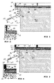
- a first embodiment of aParkab gleichprofils is illustrated in a sectional view.
- the balcony end profile is provided on an upper outer edge of a building panel 31, such as in particular a balcony slab or also a terrace slab or a comparable building slab with an upper side 32 and a front side 33.
- the balcony end profile comprises a mounting leg 11 for abutment on the top of the building panel 31 and a closing leg 12 and a water drainage leg 13.
- Mounting leg 11 and end leg 12 are orthogonal to each other in the present embodiment aligned, wherein the end leg 12 extends substantially vertically in mounting position.
- the water drainage leg 13 comprises a first section 20 directly adjoining the fastening leg, a second section 21 adjoining the first section, and a third section 22 adjoining the second section.
- the first section 20 of the water drainage leg 13 extends in the case of FIG present embodiment orthogonal to the mounting leg 11, in mounting position parallel to the end face 33 of the building panel 31, in the present embodiment, specifically vertically downwards.
- the balcony end profile is supported on the end face 33 of the building panel 31 via integrally formed on the first portion 20 of the water drainage leg 13 support means 26 from.
- the support means 26 are in the present embodiment concretely formed by two longitudinal, rounded webs.
- a drainage channel 16 is formed integrally in the balcony end profile according to the invention.
- the drainage channel 16 has upwardly designed as a longitudinal slot inlet opening 17 and down to a bottom 34. Laterally, the drainage channel 16 is bounded by an inner wall 15 and an outer wall 35.
- the outer wall 35 is formed in the present embodiment as a portion of the end leg 12.
- the inner wall 15 is formed by a thickening 19 of the mounting leg 11, from which also the first portion 20 of the water drainage leg 13 extends vertically downwards, with a downwardly open, tapered groove 36 remains between the water drainage leg 13 and drainage channel 16.
- the bottom 34 of the drainage channel 16 is provided with a plurality of equidistantly spaced discharge openings 18, which are formed as slots.
- the drainage channel 16 has a substantially pear-shaped cross-section in such a way that the inlet opening 17 is reduced in size compared with the maximum horizontal cross section of the drainage channel 16, this being achieved by two limiting webs 37, 38 delimiting the inlet opening 17.
- a surface drainage 39 is provided, which is covered by a tile floor 40 in the present embodiment. Seepage or condensation, which collects below the tile floor 40, is guided via the surface drainage 39 towards the drainage channel 16, into which it can enter via the inlet opening 17 and either directly through an outlet opening 18 located below or within the drainage channel 16 the drain openings 18 is guided.
- the adjoining the first portion 20 second section 21 to the horizontal is inclined outwardly inclined so that water runs on this section 21 to the outside.
- the adjoining third section 22 preferably extends substantially vertically and has at its lower end a drip nose 41, which ensures a defined dripping of the water from the third section 22 of the water drainage leg 13.
- Attachment means 23 for fastening a discharge channel 24 can still be provided on the water drainage leg 13, which will be explained in more detail below with reference to FIGS. 5, 6 and 8.
- the vertically extending end leg 12 may in the embodiment shown here specifically comprise one or more longitudinal predetermined breaking points 27 in order to shorten the end leg 12 to a specific desired height of the floor covering, in particular a specific desired height of the tile floor can.
- the end leg can 12 be adjusted via predetermined breaking points 27 on tile heights of 6.8 or 10 mm.
- FIGS. 3 and 4 illustrate a modified embodiment of a balcony end profile, which differs from the embodiment shown in FIGS. 1 and 2, which differs only in the design of the end leg 12.
- the end leg 12 has no predetermined breaking points 27 but rather an angled section 42 at its distal end.
- the length of the end leg 12 is not adapted to different ground heights; Rather, the end leg 12 only a fixed predetermined height for receiving the surface drainage 39 and a cover layer, such as screed, etc. on.
- a tiled floor 40 can either be designed to cover the end leg (see Fig. 11) or, alternatively, be substantially aligned with the end leg (see Fig. 12), in which case a termination by a separate tile profile 43 as is considered useful.
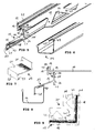
- FIG. 5 the embodiment of the terminal profile according to FIGS. 3 and 4 is shown in a perspective view, wherein the mounting leg 11 is provided with triangular punched holes 44 and 45 with screw holes.
- a discharge channel 24 is illustrated for attachment to the water drainage leg 13 of the balcony end profile.
- the fastening means 23 provided in the balcony end profile are here specifically designed as a pocket-shaped groove 46 provided below the second section 21, into which a corresponding angled inner leg 47 of the discharge channel 24 can be inserted. Both groove 46 and inner leg 47 may still be provided with locking teeth 48, 49 to ensure locking of the discharge channel 24 in the balcony end profile.
- Fig. 8 a comparison with the solution according to FIGS. 5 and 6 slightly modified embodiment is shown in a sectional view, in which case the fixing principle is the same, but the groove 46 is slightly offset in the direction of the first portion 20 out.
- the water drainage leg 12th attached discharge chute 24 surrounds the third portion 22 with the drip nose 41 formed there, so that water draining from the drip nose 41 is collected in the discharge chute 24.
- connection cover 29 which is adapted to the outer dimensions of the water drainage leg 13 and clamped on this, a butt joint of two adjacent balcony end profiles can be covered.
- the terminal cover 29 has a first vertical leg 50, an inclined second leg 51, a third leg 52 extending parallel to the first leg and a fourth leg 53 bent back in the direction of the second leg 51.
- the distal end of the first leg 50 can engage in the groove 36 between drainage channel 16 and water drainage leg 13.
- the drip nose 41 of the balcony end profile is encompassed, so that the connection overlap 29 can be fixed in each case by clamping on the balcony end profile.
- FIG. 9 an angle member 30 for forming a 90 ° -Außenwinkels using theRONab gleichprofils invention is shown in a view from above.
- the balcony end profile can have a grooving 28 both in straight training and in an embodiment as an angle element for improving the adhesive properties of pasty materials, such as tile adhesive, mortar, screed, etc.
- the upper side 32 of the building panel 31 is first sealed by a sealing layer 54, for example a bituminous layer, on which theseidab gleichprofil attached with its mounting leg 11, in particular glued and / or screwed.
- a leveling layer 55 in particular a leveling mat.
- a compensation can also be made in an alternative manner via pasty masses, in particular special leveling compounds.
- a filter layer 56 in the region of the mounting leg 11 - the surface drainage 39 placed on the drainage channel 16 adjacent a water-impermeable film 57, a drainage layer 58 and a filter mat 59.
- the filter mat 59 primarily assumes a filter function, ie it holds larger particles from the drainage layer 58, which preferably has a preferred orientation for discharging water in the direction of the balcony end profile. But the filter mat 59 can also take over part of the statics of the surface drainage 39 and thus also serve to reinforce the surface drainage 39.
- the thus formed surface drainage 39 is again covered by a glass fiber fabric 60, which can serve as a reinforcement for a screed layer or a tile adhesive or tile mortar.
- the floor covering can then optionally be completed via a screed layer or, as shown in FIGS. 10 to 12, covered by a tile floor 40.
- angular sealing segments can be used, which can be filled in an expedient arrangement by means of a reinforcement 63 made of glass fiber fabric or of synthetic textile material (see FIG and Fig. 14).
- angular corner elements 62 outer and inner corners
- angular corner elements and sealing strips can be used. In both cases, an optimal wall connection is guaranteed and made a drainage on the surface drainage 39 towards the balcony end profile.
- a concrete embodiment of a surface drainage 39 is again illustrated.
- the surface drainage 39 initially has a water-impermeable film 57 formed by an insulating film.
- the drainage layer 58 is formed by longitudinal first and second webs 64, 65.
- the first webs 64 lie directly on the water-impermeable film with which they are glued or welded, for example.
- second webs 65 are the first webs 64 crossing on the first webs, for example, attached by gluing or welding. It is thus created a drainage grid with a diamond-shaped basic pattern, wherein the dewatering direction along the first webs 64 and along the longitudinal axes of the diamond-shaped structure runs.
- a filter mat 59 is still placed, which may be formed of synthetic material.
- the purpose of the filter mat 59 is to keep particles from the drainage layer 58 in order to prevent clogging.
- the surface drainage 39 is expediently provided in the form of a web and, in order to be able to fit adjacent webs together, overlap sections 66, 67, in particular, the water-impermeable film 57 protrudes on one side to form an overlap section 66 via the drainage layer 58, whereas on the opposite side of the filter mat 59 also projects with respect to the drainage layer 58 to form an overlap portion 67.
- the drainage layer 58 is connected flush; the overlapping sections 66, 67 provide for a partial covering of water-impermeable film 57 or filter mat 59.
- Both the angular sealing segments 62 and the surface drainage 39 described here are claimed to be essential to the invention, on the one hand in combination with the previously described balcony border profile and independently, for example when using to be drained building surfaces, such as terraces or building surfaces in the interior.
- the surface drainage 39 described here it is possible to decouple soils, in particular tile floors from the underlying building surface, ie to lay tension-free or floating.
- the overall arrangement of a balcony drainage suitably claims the balcony end profile as well as surface drainage and optionally angular sealing segments 62.
Landscapes
- Engineering & Computer Science (AREA)
- Architecture (AREA)
- Civil Engineering (AREA)
- Structural Engineering (AREA)
- Floor Finish (AREA)
- Building Environments (AREA)
- Paper (AREA)
- Diaphragms For Electromechanical Transducers (AREA)
- Steps, Ramps, And Handrails (AREA)
Abstract
Description
Die Erfindung betrifft ein Balkonabschlussprofil umfassend einen Befestigungsschenkel, ein im Wesentlichen senkrecht hierzu ausgerichteten und in Montagelage sich nach oben erstreckenden Abschlussschenkel sowie einen Wasserablaufschenkel in Montagelage unterhalb des Abschlussschenkels, wobei in einem zwischen Befestigungsschenkel und Abschlussschenkel ausgebildeten Eckbereich Wasserablaufmittel vorgesehen sind.The invention relates to a Balkonabschlussprofil comprising a mounting leg, a substantially perpendicular thereto aligned and in mounting position upwardly extending end leg and a water drainage leg in mounting position below the end leg, wherein in a formed between the mounting leg and end leg corner drainage means are provided.
Ein derartiges Balkonabschlussprofil ist beispielsweise aus der DE 202 18 833 U1 bekannt. Dort wird Wasser über eine Flächendrainage zum Rand des Balkons hin entwässert und gelangt am dortigen Balkonabschlussprofil über in einem vertikal verlaufenden Profilabschnitt vorgesehene Langlöcher nach außen. Bei dieser Ausgestaltung besteht jedoch das Problem, dass die diskret angeordneten, voneinander beabstandeten vertikal ausgerichteten Langlöcher sich zusetzen können, mit der Folge, dass sich bereichsweise Feuchtigkeit aufstaut und die angestrebte Entwässerung beeinträchtigt oder verunmöglicht wird.Such a balcony end profile is known for example from DE 202 18 833 U1. There, water is drained via a surface drainage to the edge of the balcony out and gets to the local balcony border profile over in a vertical profile section provided slots to the outside. In this embodiment, however, there is the problem that the discretely arranged, spaced apart vertically aligned slots can enforce, with the result that some dammed up moisture and the desired drainage is impaired or impossible.
Die Aufgabe der vorliegenden Erfindung besteht gegenüber dem vorgenannten Stand der Technik darin, eine noch verbesserte Entwässerung zu schaffen.The object of the present invention over the aforementioned prior art is to provide an even better drainage.
Diese Aufgabe wird mit einem Balkonabschlussprofil nach den Merkmalen des Anspruches 1 gelöst. Vorteilhafte Weiterbildungen sind in den Unteransprüchen angegeben.This object is achieved with a balcony end profile according to the features of claim 1. Advantageous developments are specified in the subclaims.
Ein Kerngedanke der vorliegenden Erfindung besteht darin, dass die Wasserablaufmittel eine integral mit dem Profil ausgebildete Entwässerungsrinne umfassen. Gegenüber der Flächendrainage stehen damit nicht mehr nur lediglich diskrete Entwässerungsöffnungen zur Verfügung; vielmehr ist eine eigens zu Entwässerungszwecken vorgesehene Entwässerungsrinne integral mit dem Profil ausgebildet.A central idea of the present invention is that the drainage means comprise a drainage channel integrally formed with the profile. Compared to the surface drainage are no longer only discrete drainage openings available; rather, one is specially designed for drainage purposes drainage channel integrally formed with the profile.
Nach einem besonders bevorzugten Aspekt der vorliegenden Erfindung umfasst die Entwässerungsrinne eine obere Einlauföffnung, die als durchgängiger Längsschlitz ausgebildet ist. Anders als bei den aus dem Stand der Technik bekannten beabstandeten diskreten Entwässerungsöffnungen ist hier eine kontinuierlich durchgehende Entwässerungsmöglichkeit geschaffen, bei der das Risiko des Verstopfens erheblich minimiert ist. Sollte tatsächlich lokal der durchgängige Längsschlitz bereichsweise durch Verschmutzungen überdeckt werden, so ist beidseits der Verschmutzungsstelle weiterhin ein Ablauf gewährleistet.According to a particularly preferred aspect of the present invention, the drainage channel comprises an upper inlet opening, which is formed as a continuous longitudinal slot. Unlike the discrete dewatering apertures spaced apart from the prior art, this provides a continuous drainage capability in which the risk of clogging is significantly minimized. If locally, the continuous longitudinal slot is partially covered by dirt, so on both sides of the pollution point continues to ensure a flow.
Die Einlauföffnung kann dabei vorzugsweise im Wesentlichen horizontal ausgerichtet sein derart, dass Wasser von oben in die Einlauföffnung im Wesentlichen vertikal in die Entwässerungsrinne einlaufen kann.The inlet opening can preferably be aligned substantially horizontally in such a way that water can enter into the inlet opening substantially vertically into the drainage channel from above.
Während theoretisch ein Ablauf des in der Entwässerungsrinne gesammelten Wassers rein durch seitige Öffnungen gewährleistet sein könnte, wird es gemäß der Erfindung bevorzugt, in der Entwässerungsrinne eine Mehrzahl zueinander beabstandeter Ablauföffnungen auch über den Längsverlauf der Entwässerungsrinne vorzusehen.While theoretically a flow of the water collected in the drainage channel could be ensured purely by openings on the side, according to the invention it is preferred to provide a plurality of drainage openings spaced apart from one another over the longitudinal course of the drainage channel in the drainage channel.
Die Wasserabfuhr ist dann besonders günstig, wenn die Ablauföffnungen in Montagelage im Wesentlichen lotrecht unterhalb der Einlauföffnung angeordnet sind.The drainage of water is particularly favorable when the drainage openings are arranged in the mounting position substantially vertically below the inlet opening.
Obwohl das Risiko eines Verstopfens der Ablauföffnungen innerhalb der erfindungsgemäß vorgesehenen Entwässerungsrinne im Vergleich zum Risiko des Verstopfens der Ablauföffnungen nach dem Stand der Technik erheblich verringert ist, wird es dennoch bevorzugt, die Ablauföffnungen als Langlöcher auszubilden. Dadurch wird es möglich, Ablauföffnungen mit einer gewissen flächenmäßigen Ausdehnung vorzusehen, so dass das Risiko des Zusetzens erheblich verringert ist.Although the risk of plugging the drainage holes within the drainage channel provided according to the invention is considerably reduced compared to the risk of clogging the drainage holes according to the prior art, it is still preferable to form the drainage holes as elongated holes. This makes it possible to provide drainage holes with a certain areal extent, so that the risk of clogging is considerably reduced.
In einer konkreten Ausgestaltung wird die innere Wandung der Entwässerungsrinne durch eine Verdickung am Befestigungsschenkel gebildet. Die Verdickung am Befestigungsschenkel kann aus statischen Gesichtspunkten zweckmäßig sein, wobei die gleichzeitige Ausbildung der inneren Wandung durch diese Verdickung eine relativ kompakte Bauweise des Balkonabschlussprofils gestattet.In a specific embodiment, the inner wall of the drainage channel is formed by a thickening on the attachment leg. The Thickening on the mounting leg can be useful from a static point of view, wherein the simultaneous formation of the inner wall by this thickening allows a relatively compact design of the balcony end profile.
An diese Verdickung kann sich ebenfalls der Wasserablaufschenkel anschließen, was insbesondere aus statischen Überlegungen sinnvoll ist. In einer konkreten Ausgestaltung weist der Wasserablaufschenkel einen dem Befestigungsschenkel zugewandten, im Wesentlichen senkrecht zum Befestigungsschenkel verlaufenden ersten Abschnitt (vertikalen Abschnitt) sowie einen sich im Stumpfen Winkel anschließenden, zweiten Abschnitt auf. Der sich im stumpfen Winkel anschließende zweite Abschnitt verläuft in Montagelage schräg nach unten derart, dass eine Wasserablaufebene gebildet wird.This thickening can also be followed by the water drainage leg, which is useful in particular for static considerations. In a specific embodiment, the water drainage leg has a first section (vertical section), which faces the fastening leg and runs essentially perpendicular to the fastening leg, and a second section adjoining at an obtuse angle. The adjoining the obtuse angle second section extends in mounting position obliquely downwards such that a water drainage plane is formed.
Nach einem weiter bevorzugten Aspekt weist der Wasserablaufschenkel noch einen sich an den zweiten Abschnitt anschließenden Dritten Abschnitt auf, der in Richtung auf den ersten Abschnitt zurückgebogen ist und insbesondere zum ersten Abschnitt parallel (ebenfalls vertikal) verläuft. Am untersten Ende des dritten Abschnitts kann eine Tropfnase ausgebildet sein, um ein definiertes Abtropfen von Wasser zu gewährleisten.According to a further preferred aspect, the water drainage leg still has a third section adjoining the second section, which is bent back in the direction of the first section and in particular runs parallel (also vertically) to the first section. At the lowermost end of the third section may be formed a drip nose to ensure a defined dripping of water.
In einer weiteren Ausgestaltung können am Wasserablaufschenkel Befestigungsmittel zur Befestigung einer Abführrinne vorgesehen sein. In der Abführrinne kann damit Wasser aus der Flächendrainage sowie von außen auftreffendes Regenwasser abgeführt werden.In a further embodiment, fastening means for fastening a discharge channel can be provided on the water drainage leg. In the discharge channel water can thus be removed from the surface drainage and incident rainwater from the outside.
Am Wasserablaufschenkel sind bevorzugtermaßen weiterhin Abstützmittel insbesondere mindestens ein längsverlaufender Steg zur Anlage an eine vertikale Stirnseite eines Balkons vorgesehen. Durch eine direkte Anlage des Wasserablaufschenkels am Gebäude wird die Stabilität der Gesamtkonstruktion erhöht.Supporting means, in particular at least one longitudinal web, are furthermore preferably provided on the water-drainage leg for engagement with a vertical end face of a balcony. The stability of the overall construction is increased by a direct installation of the water drain leg on the building.
Der in Montagelage nach oben gerichtete Abschlussschenkel kann mindestens eine, vorzugsweise mehrere längsverlaufende Sollbruchstellen aufweisen, um den Abschlussschenkel auf eine gewünschte Länge kürzen zu können. Damit kann der Abschlussschenkel auf verschiedene Höhen eines jeweils gewünschten Bodenbelages, beispielsweise auf verschiedene Fliesenhöhen angepasst werden.The upwardly directed in mounting position end leg may have at least one, preferably a plurality of longitudinal predetermined breaking points in order to shorten the tail to a desired length can. This allows the end leg to different heights of one each desired flooring, for example, be adapted to different tile heights.
Nach einem weiteren Aspekt der vorliegenden Erfindung ist der Befestigungsschenkel mit Aufrauungen oder eine Rillung versehen, um die Haftfähigkeiten beispielweise für Estrich oder einen Fliesenkleber zu erhöhen.According to another aspect of the present invention, the attachment leg is provided with roughening or grooving in order to increase the adhesivities, for example, to screed or a tile adhesive.
Es versteht sich von selbst, dass das erfindungsgemäße Balkonabschlussprofil nicht nur geradlinig verlaufend ausgebildet sein kann; vielmehr sind auch Innen- oder Außenwinkel möglich, die nicht nur auf 90°-Winkel beschränkt sein müssen.It goes without saying that the balcony end profile according to the invention can not only be designed to extend in a straight line; rather, internal or external angles are possible, which need not be limited only to 90 ° angle.
Die Erfindung wird nachstehend auch hinsichtlich weiterer Merkmale und Vorteile unter Bezugnahme auf konkrete Ausführungsbeispiele näher erläutert.The invention will be explained below with regard to further features and advantages with reference to specific embodiments.
Hierbei zeigen:
- Fig. 1
- eine Schnittansicht durch eine Ausführungsform eines erfindungsgemäßen Balkonabschlussprofils in Montagelage
- Fig. 2
- einen vergrößerten Ausschnitt aus Fig. 1
- Fig. 3
- eine Schnittansicht einer alternativen Ausführungsform des erfindungsgemäßen Balkonabschlussprofils in Montagelage
- Fig. 4
- einen vergrößerten Ausschnitt aus Fig. 3
- Fig. 5
- eine perspektivische Ansicht der Ausführungsform des Balkonabschlussprofils nach Fig. 3
- Fig. 6
- eine Ausführungsform einer Abführrinne zur Verwendung mit dem Balkonabschlussprofil nach Fig. 5
- Fig. 7
- eine Ausführungsform einer Anschlussüberdeckung
- Fig. 8
- eine Schnittansicht durch eine Ausbildungsform des Balkonabschlussprofils mit einer darin befestigten Abführrinne nach Fig. 6
- Fig. 9
- ein Winkelelement einer Ausführungsform des Balkonabschlussprofils
- Fig. 10
- eine perspektivische Teilschnittansicht der Einbauanordnung einer Ausführungsform des Balkonabschlussprofils
- Fig. 11
- eine perspektivische Teilquerschnittsansicht der Einbauanordnung einer modifizierten Ausführungsform des Balkonabschlussprofils
- Fig. 12
- eine perspektivische Teilquerschnittsansicht der Einbauanordnung einer nochmals modifizierten Ausführungsform des Balkonabschlussprofils
- Fig. 13
- eine Ausführungsform eines winkelförmigen Dichtungssegments für Innenecken
- Fig. 14
- eine Ausführungsform eines winkelförmigen Dichtungssegments für Außenecken
- Fig. 15
- eine Ausführungsform einer Flächendrainage, die insbesondere in Kombination mit dem erfindungsgemäßen Balkonabschlussprofil zum Einsatz gelangen kann
- Fig. 1
- a sectional view through an embodiment of a Balkonabschlussprofils invention in mounting position
- Fig. 2
- an enlarged section of Fig. 1st
- Fig. 3
- a sectional view of an alternative embodiment of the balcony end profile according to the invention in mounting position
- Fig. 4
- an enlarged section of Fig. 3rd
- Fig. 5
- a perspective view of the embodiment of the balcony end profile of FIG .. 3
- Fig. 6
- an embodiment of a discharge chute for use with the Balkonabschlussprofil of FIG. 5
- Fig. 7
- an embodiment of a connection overlap
- Fig. 8
- a sectional view through an embodiment of the Balkonabschlussprofils with a discharge channel attached in Fig. 6
- Fig. 9
- an angular element of an embodiment of the balcony end profile
- Fig. 10
- a partial perspective sectional view of the mounting arrangement of an embodiment of the balcony end profile
- Fig. 11
- a partial perspective cross-sectional view of the mounting arrangement of a modified embodiment of the Balkonabschlussprofils
- Fig. 12
- a partial perspective cross-sectional view of the mounting arrangement of a further modified embodiment of the balcony end profile
- Fig. 13
- an embodiment of an angular sealing segment for inner corners
- Fig. 14
- an embodiment of an angular sealing segment for outside corners
- Fig. 15
- an embodiment of a surface drainage, which can be used in particular in combination with the balcony border profile according to the invention
In den Fig. 1 und 2 ist eine erste Ausführungsform eines Balkonabschlussprofils in einer Schnittansicht veranschaulicht. Das Balkonabschlussprofil wird an einer oberen äußeren Kante einer Gebäudeplatte 31, wie insbesondere einer Balkonplatte oder auch einer Terrassenplatte oder einer vergleichbaren Gebäudeplatte mit einer Oberseite 32 und einer Stirnseite 33 vorgesehen.In Figs. 1 and 2, a first embodiment of a Balkonabschlussprofils is illustrated in a sectional view. The balcony end profile is provided on an upper outer edge of a
Das Balkonabschlussprofil umfasst einen Befestigungsschenkel 11 zur Anlage auf der Oberseite der Gebäudeplatte 31 sowie einen Abschlussschenkel 12 und einen Wasserablaufschenkel 13. Befestigungsschenkel 11 und Abschlussschenkel 12 sind bei der vorliegenden Ausführungsform orthogonal zueinander ausgerichtet, wobei sich der Abschlussschenkel 12 in Montagelage im Wesentlichen vertikal erstreckt. Der Wasserablaufschenkel 13 umfasst bei der vorliegenden Ausführungsform einen sich unmittelbar an dem Befestigungsschenkel anschließenden ersten Abschnitt 20, einen sich an den ersten Abschnitt anschließenden zweiten Abschnitt 21 sowie einen sich am zweiten Abschnitt anschließenden dritten Abschnitt 22. Der erste Abschnitt 20 des Wasserablaufschenkels 13 verläuft bei der vorliegenden Ausführungsform orthogonal zu dem Befestigungsschenkel 11, in Montagelage parallel zur Stirnseite 33 der Gebäudeplatte 31, bei der vorliegenden Ausführungsform konkret vertikal nach unten.
Das Balkonabschlussprofil stützt sich an der Stirnseite 33 der Gebäudeplatte 31 über integral am ersten Abschnitt 20 des Wasserablaufschenkels 13 angeformte Abstützmittel 26 ab. Die Abstützmittel 26 sind bei der vorliegenden Ausführungsform konkret durch zwei längsverlaufende, gerundete Stege ausgebildet.The balcony end profile comprises a mounting
The balcony end profile is supported on the
In einem Eckbereich 14 zwischen Abschlussschenkel 12 und Befestigungsschenkel 11 ist beim erfindungsgemäßen Balkonabschlussprofil eine Entwässerungsrinne 16 integral ausgebildet. Die Entwässerungsrinne 16 weist nach oben eine als längsverlaufener Schlitz ausgebildete Einlauföffnung 17 und nach unten einen Boden 34 auf. Seitlich wird die Entwässerungsrinne 16 durch eine innere Wandung 15 und eine äußere Wandung 35 begrenzt. Die äußere Wandung 35 ist bei der vorliegenden Ausführungsform als Abschnitt des Abschlussschenkels 12 ausgebildet. Die innere Wandung 15 wird durch eine Verdickung 19 des Befestigungsschenkels 11 gebildet, von der sich auch der erste Abschnitt 20 des Wasserablaufschenkels 13 vertikal nach unten erstreckt, wobei zwischen Wasserablaufschenkel 13 und Entwässerungsrinne 16 eine nach unten offene, sich verjüngende Nut 36 verbleibt.In a
Der Boden 34 der Entwässerungsrinne 16 ist mit einer Mehrzahl äquidistant voneinander beabstandeter Ablauföffnungen 18 versehen, die als Langlöcher ausgebildet sind. Die Entwässerungsrinne 16 weist einen im Wesentlichen birnenförmigen Querschnitt auf derart, dass die Einlauföffnung 17 gegenüber dem maximalen horizontalen Querschnitt der Entwässerungsrinne 16 verkleinert ist, wobei dies durch zwei die Einlauföffnung 17 begrenzende Begrenzungsstege 37, 38 erreicht wird.The bottom 34 of the
Oberhalb des Befestigungsschenkels 11 und gleichzeitig die Entwässerungsrinne 16 überdeckend ist eine Flächendrainage 39 vorgesehen, die bei der vorliegenden Ausführungsform durch einen Fliesenboden 40 überdeckt ist. Sicker- oder Kondenswasser, das sich unterhalb des Fliesenbodens 40 sammelt, wird über die Flächendrainage 39 hin auf die Entwässerungsrinne 16 geführt, in die es über die Einlauföffnung 17 einlaufen kann und entweder direkt durch eine darunter befindliche Ablauföffnung 18 fliest oder innerhalb der Entwässerungsrinne 16 zu den Ablauföffnungen 18 geführt wird.Above the mounting
Das aus den Ablauföffnungen 18 austretende Wasser trifft auf den Wasserablaufschenkel 13 und wird durch diesen von der Gebäudeplatte 31 weggeführt. Hierzu ist der sich an den ersten Abschnitt 20 anschließende zweite Abschnitt 21 zur Horizontalen nach außen geneigt ausgebildet, so dass Wasser auf diesen Abschnitt 21 nach außen abläuft. Der sich anschließende dritte Abschnitt 22 verläuft bevorzugtermaßen im Wesentlichen vertikal und weist an seinem unteren Ende eine Tropfnase 41 auf, die ein definiertes Abtropfen des Wassers vom dritten Abschnitt 22 des Wasserablaufschenkels 13 gewährleistet.The water emerging from the
Am Übergang zwischen ersten Abschnitt 20 und zweiten Abschnitt 21 des Wasserablaufschenkels 13 kann noch ein sich nach unten erstreckender Aufstecksteg 61 angeformt sein, der zur Ausbildung einer Schattenfuge, aber auch zum Aufstecken einer eventuellen Kaschierungsblende dienen kann. Eine derartige Kaschierungsblende kann gewünscht sein, um unsaubere Stellen der Gebäudeplatte 31, eventuell Feuchtigkeitsausblühungen, etc. abzudecken.At the transition between the
Am Wasserablaufschenkel 13 können noch Befestigungsmittel 23 zur Befestigung einer Abführrinne 24 vorgesehen sein, was weiter unten noch anhand der Fig. 5, 6 und 8 näher erläutert wird.Attachment means 23 for fastening a
Der vertikal verlaufende Abschlussschenkel 12 kann in der hier konkret dargestellten Ausführungsform eine oder mehrere längsverlaufende Sollbruchstellen 27 umfassen, um den Abschlussschenkel 12 auf eine konkret gewünschte Höhe des Bodenbelages, insbesondere eine konkret gewünschte Höhe des Fliesenbodens kürzen zu können. Insbesondere kann der Abschlussschenkel 12 über Sollbruchstellen 27 auf Fliesenhöhen von 6,8 oder 10 mm angepasst werden.The vertically extending
In den Fig. 3 und 4 ist eine gegenüber der in den Fig. 1 und 2 dargestellten Ausführungsform modifizierte Ausführungsform eines Balkonabschlussprofils veranschaulicht, das sich alleine in der Ausbildung des Abschlussschenkels 12 unterscheidet. Der Abschlussschenkel 12 weist bei der in Fig. 3 und 4 veranschaulichten Ausführungsform keine Sollbruchstellen 27 sondern an seinem distalen Ende eine Abwinklung 42 auf. Anders als das Balkonabschlussprofil nach den Fig. 1 und 2 ist hier die Länge des Abschlussschenkels 12 nicht auf verschiedene Bodenhöhen anpassbar ausgebildet; vielmehr weist der Abschlussschenkel 12 nur eine fest vorgegebene Höhe zur Aufnahme der Flächendrainage 39 sowie eine Deckschicht, wie Estrich, etc. auf. Ist ein Fliesenboden 40 gewünscht, so kann dieser entweder den Abschlussschenkel überdeckend (vgl. Fig. 11) ausgebildet werden oder alternativ im Wesentlichen mit dem Abschlussschenkel fluchtend verlegt werden (vgl. Fig. 12), wobei hierbei ein Abschluss durch ein separates Fliesenprofil 43 als sinnvoll erachtet wird.FIGS. 3 and 4 illustrate a modified embodiment of a balcony end profile, which differs from the embodiment shown in FIGS. 1 and 2, which differs only in the design of the
In Fig. 5 ist die Ausführungsform des Abschlussprofils nach den Fig. 3 und 4 in perspektivischer Ansicht dargestellt, wobei der Befestigungsschenkel 11 mit dreieckförmigen Ausstanzungen 44 sowie mit Schraubenlöchern 45 versehen ist.In Fig. 5, the embodiment of the terminal profile according to FIGS. 3 and 4 is shown in a perspective view, wherein the mounting
In Fig. 6 ist eine Ausführungsform einer Abführrinne 24 zur Befestigung im Wasserablaufschenkel 13 des Balkonabschlussprofils veranschaulicht. Die im Balkonabschlussprofil vorgesehenen Befestigungsmittel 23 sind hier konkret als unterhalb des zweiten Abschnitts 21 vorgesehene taschenförmige Nut 46 ausgebildet, in die sich ein entsprechend abgewinkelter innerer Schenkel 47 der Abführrinne 24 einschieben lässt. Sowohl Nut 46 als auch innerer Schenkel 47 können noch mit Rastzähnen 48, 49 versehen sein, um eine Verrastung der Abführrinne 24 im Balkonabschlussprofil zu gewährleisten.In Fig. 6, an embodiment of a
In Fig. 8 ist eine gegenüber der Lösung nach den Fig. 5 und 6 leicht modifizierte Ausführungsform in einer Schnittansicht dargestellt, wobei hier das Befestigungsprinzip dasselbe ist, allerdings die Nut 46 etwas in Richtung auf den ersten Abschnitt 20 hin versetzt ist. Die am Wasserablaufschenkel 12 befestigte Abführrinne 24 umgreift den dritten Abschnitt 22 mit der dort angeformten Tropfnase 41, so dass von der Tropfnase 41 ablaufendes Wasser in der Abführrinne 24 aufgefangen wird.In Fig. 8, a comparison with the solution according to FIGS. 5 and 6 slightly modified embodiment is shown in a sectional view, in which case the fixing principle is the same, but the
Fig. 7 veranschaulicht eine auf das Balkonabschlussprofil, insbesondere den Wasserablaufschenkel 13 außen aufschiebbare Anschlussüberdeckung 29. Mit Hilfe dieser Anschlussüberdeckung 29, die den Außenabmessungen des Wasserablaufschenkels 13 angepasst und auf diesem klemmend gehalten wird, kann eine Stoßfuge zweier aneinander grenzender Balkonabschlussprofile überdeckt werden. Die Anschlussüberdeckung 29 weist einen ersten vertikalen Schenkel 50, einen geneigten zweiten Schenkel 51, einen parallel zum ersten Schenkel verlaufenden dritten Schenkel 52 sowie einen zurück, in Richtung auf den zweiten Schenkel 51 umgebogenen vierten Schenkel 53 auf.With the help of this
Das distale Ende des ersten Schenkels 50 kann in die Nut 36 zwischen Entwässerungsrinne 16 und Wasserablaufschenkel 13 eingreifen. Mittels des vierten Schenkels 53 wird die Tropfnase 41 des Balkonabschlussprofils umgriffen, so dass die Anschlussüberdeckung 29 sich jeweils klemmend auf dem Balkonabschlussprofil befestigen lässt.The distal end of the
In Fig. 9 ist ein Winkelelement 30 zur Ausbildung eines 90°-Außenwinkels mit Hilfe des erfindungsgemäßen Balkonabschlussprofils in einer Ansicht von oben dargestellt. Das Balkonabschlussprofil kann sowohl in gerader Ausbildung als auch in einer Ausbildung als Winkelelement eine Rillung 28 aufweisen zur Verbesserung der Hafteigenschaften von pastösen Massen, wie Fliesenkleber, Mörtel, Estrich, etc.In Fig. 9, an
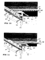
In den Fig. 10, 11 und 12 sind für die Ausführungsformen mit jeweils unterschiedlich ausgebildeten Abschlussschenkeln Einbauanordnungen veranschaulicht, wobei in Fig. 10 die höhenanpassbare Ausführungsform des Balkonabschlussprofils, in den Fig. 11 und 12 die Ausführungsform mit Abschlussschenkel von fest vorgegebener Höhe veranschaulicht sind.10, 11 and 12 are illustrated for the embodiments, each with differently shaped graduated legs installation arrangements, wherein in Fig. 10, the height-adjustable embodiment of the Balkonabschlussprofils, in Figs. 11 and 12, the embodiment with end leg of fixed predetermined height are illustrated.
In allen drei Fällen wird die Oberseite 32 der Gebäudeplatte 31 zunächst durch eine Versiegelungsschicht 54, beispielsweise eine Bitumenschicht versiegelt, auf die das Balkonabschlussprofil mit seinem Befestigungsschenkel 11 befestigt, insbesondere verklebt und/oder verschraubt wird. Zum Ausgleich der Höhe des Befestigungsschenkels wird bis an den Befestigungsschenkel 11 angrenzend auf die Versiegelungsschicht 54 eine Ausgleichsschicht 55, insbesondere eine Ausgleichsmatte aufgebracht. Ein Ausgleich kann selbstverständlich in alternativer Weise auch über pastöse Massen, insbesondere spezielle Nivelliermassen, erfolgen. Auf den Befestigungsschenkel 11 und die Ausgleichsschicht 55 wird - ggf. unter Zwischenlegung einer Filterschicht 56 im Bereich des Befestigungsschenkels 11 - die Flächendrainage 39 aufgelegt, die bis an die Entwässerungsrinne 16 angrenzend eine wasserundurchlässige Folie 57, eine Drainageschicht 58 sowie eine Filtermatte 59 aufweist. Die Filtermatte 59 übernimmt in erster Linie eine Filterfunktion, d.h. sie hält größere Partikel von der Drainageschicht 58, die bevorzugtermaßen eine Vorzugsausrichtung zum Ableiten von Wasser in Richtung auf das Balkonabschlussprofil aufweist, ab. Die Filtermatte 59 kann aber auch einen Teil der Statik der Flächendrainage 39 übernehmen und somit auch zur Armierung der Flächendrainage 39 dienen. Die so gebildete Flächendrainage 39 wird nochmals von einem Glasfasergewebe 60 überdeckt, das als Armierung für eine Estrichschicht oder einen Fliesenkleber bzw. Fliesenmörtel dienen kann. Der Bodenbelag kann dann wahlweise über eine Estrichschicht abgeschlossen werden oder wie in den Fig. 10 bis 12 dargestellt durch einen Fliesenboden 40 überdeckt werden.In all three cases, the upper side 32 of the
Um Wasser von aufragenden Gebäudeteilen, wie Wänden, etc. abzuleiten und in die Flächendrainage 39 zu überführen, können winkelförmige Dichtungssegmente zur Anwendung kommen, die sich in zweckmäßiger Anordnung über eine Armierung 63 aus Glasfasergewebe oder aus synthetischem Textilmaterial verspachteln lassen (vgl. Fig. 13 und Fig. 14). Insbesondere für mit Ecken versehene Wände können winkelförmige Eckelemente 62 (Außen- und Innenecken) bereit gehalten werden, die für eine Abfuhr des Wassers von der Wand weg in die Flächendrainage 39 sorgen. Anstelle von winkelförmigen Eckelementen können auch Dichtungsbänder zur Anwendung gelangen. In beiden Fällen wird ein optimaler Wandanschluss gewährleistet und eine Entwässerung über die Flächendrainage 39 hin zum Balkonabschlussprofil vorgenommen.In order to dissipate water from towering parts of buildings, such as walls, etc., and to transfer them into the
In Fig. 15 ist eine konkrete Ausführungsform für eine Flächendrainage 39 nochmals veranschaulicht. Die Flächendrainage 39 weist zunächst eine durch eine Isolationsfolie gebildete wasserundurchlässige Folie 57 auf. Die Drainageschicht 58 wird durch längsverlaufende erste und zweite Stege 64, 65 gebildet. Die ersten Stege 64 liegen dabei unmittelbar auf der wasserundurchlässigen Folie auf, mit der sie beispielsweise verklebt oder verschweißt sind. In einem spitzen Winkel von etwa 60° sind zweite Stege 65 die ersten Stege 64 kreuzend auf den ersten Stegen, beispielsweise durch Kleben oder Schweißen befestigt. Es wird so ein Drainagegitter mit einem rautenförmigen Grundmuster geschaffen, wobei die Entwässerungsrichtung entlang der ersten Stege 64 bzw. entlang der Längsachsen der rautenförmigen Struktur verläuft. Auf die durch die rautenförmige Struktur gebildete Drainageschicht 58 wird noch eine Filtermatte 59 aufgelegt, die aus synthetischen Material gebildet sein kann. Die Filtermatte 59 dient dem Zweck, Partikel aus der Drainageschicht 58 fernzuhalten, um ein Verstopfen bzw. Zusetzen zu verhindern. Die Flächendrainage 39 wird zweckmäßigerweise bahnenförmig vorgehalten und weist, um benachbarte Bahnen möglichst gut aneinander fügen zu können, jeweils Überlappungsabschnitte 66, 67 auf, konkret ragt die wasserundurchlässige Folie 57 an einer Seite unter Ausbildung eines Überlappungsabschnittes 66 über die Drainageschicht 58 vor, wohingegen auf der gegenüberliegenden Seite die Filtermatte 59 unter Ausbildung eines Überlappungsabschnittes 67 ebenfalls gegenüber der Drainageschicht 58 vorragt. Bei Aneinanderfügen zweier Bahnen wird jeweils die Drainageschicht 58 bündig angeschlossen; die Überlappungsabschnitte 66, 67 sorgen für eine bereichsweise Überdeckung von wasserundurchlässiger Folie 57 bzw. Filtermatte 59.In Fig. 15, a concrete embodiment of a
Sowohl die winkelförmigen Dichtungssegmente 62 als auch die hier beschriebene Flächendrainage 39 werden als erfindungswesentlich und zwar einerseits in Kombination mit dem zuvor beschriebenen Balkonabschlussprofil als auch unabhängig, beispielweise bei Anwendung von zu entwässernden Gebäudeflächen, wie Terrassen oder auch Gebäudeflächen im Innenbereich etc. beansprucht. Mittels der hier beschriebenen Flächendrainage 39 wird es möglich, Böden, insbesondere Fliesenböden von der darunter liegenden Gebäudefläche zu entkoppeln, d. h. spannungsfrei bzw. schwimmend zu verlegen. In der Kombination mit dem erfindungsgemäßen Balkonabschlussprofil wird auch die Gesamtanordnung einer Balkonentwässerung passend das Balkonabschlussprofil sowie Flächendrainage sowie ggf. winkelförmige Dichtungssegmente 62 beansprucht.Both the
- 1111
- Befestigungsschenkelfastening leg
- 1212
- Abschlussschenkelfinal leg
- 1313
- WasserablaufschenkelWater drain leg
- 1414
- Eckbereichcorner
- 15fifteen
- innere Wandunginner wall
- 1616
- Entwässerungsrinnedrainage channel
- 1717
- Einlauföffnunginlet opening
- 1818
- Ablauföffnungendrain holes
- 1919
- Verdickungthickening
- 2020
- erster Abschnittfirst section
- 2121
- zweiter Abschnittsecond part
- 2222
- dritter Abschnittthird section
- 2323
- Befestigungsmittelfastener
- 2424
- Abführrinnedischarge chute
- 2626
- Abstützmittelsupport means
- 2727
- SollbruchstelleBreaking point
- 2828
- Rillungcreasing
- 2929
- AnschlussüberdeckungConnection coverage
- 3030
- Winkelelementangle element
- 3131
- Gebäudeplattebuilding slab
- 3232
- Oberseitetop
- 3333
- Stirnseitefront
- 3434
- Boden (Entwässerungsrinne)Floor (drainage channel)
- 3535
- äußere Wandungouter wall
- 3636
- Nutgroove
- 37, 3837, 38
- Begrenzungsstegelimiting webs
- 3939
- Flächendrainagedrainage area
- 4040
- Fliesenbodentiled floor
- 4141
- Tropfnaseclapboard
- 4242
- Abwinkelungangulation
- 4343
- Fliesenprofiltile profile
- 4444
- Ausstanzungenouts
- 4545
- Schraubenlöcherscrew holes
- 4646
- Nut (Befestigungsmittel)Groove (fastener)
- 4747
- innerer Schenkelinner thigh
- 48, 4948, 49
- Rastzähnelocking teeth
- 5050
- erster Schenkelfirst leg
- 5151
- zweiter Schenkelsecond leg
- 5252
- dritter Schenkelthird thigh
- 5353
- vierter Schenkelfourth leg
- 5454
- Versiegelungsschichtsealing layer
- 5555
- Ausgleichsschichtleveling layer
- 5656
- Filterschichtfilter layer
- 5757
- wasserundurchlässige Foliewater-impermeable film
- 5858
- Drainageschichtdrainage layer
- 5959
- Filtermattefilter mat
- 6060
- GlasfasergewebeGlass fiber fabrics
- 6161
- AufsteckstegAufstecksteg
- 6262
- winkelförmige Dichtungselementeangular sealing elements
- 6363
- Armierungreinforcement
- 64, 6564, 65
- StegeStege
- 66,6766.67
- Überlappungsabschnitteoverlap portions
Claims (13)
dadurch gekennzeichnet,
dass die Wasserablaufmittel eine integral mit dem Profil ausgebildete Entwässerungsrinne (16) umfassen.Balcony end profile, comprising a mounting leg (11), a substantially perpendicular thereto aligned and in mounting position upwardly extending end leg (12) and a water drainage leg (13) in the mounting position below the end leg (12), wherein in between fastening leg (11) and End legs (12) formed corner region (14) water drainage means are provided,
characterized,
in that the water drainage means comprise a drainage channel (16) formed integrally with the profile.
dadurch gekennzeichnet,
dass die Entwässerungsrinne (16) eine obere Einlauföffnung (17) umfasst, die als durchgängiger Längsschlitz ausgebildet ist.Balcony end profile according to claim 1,
characterized,
that the drainage channel (16) comprises an upper inlet opening (17) formed as a continuous longitudinal slot.
dadurch gekennzeichnet,
dass die Entwässerungsrinne (16) eine Mehrzahl zueinander beabstandeter Ablauföffnungen (18) umfasst.Balcony end profile according to claim 1 or 2,
characterized,
in that the drainage channel (16) comprises a plurality of mutually spaced drainage openings (18).
dadurch gekennzeichnet,
dass die Ablauföffnungen (18) in Montagelage im Wesentlichen lotrecht unterhalb der Einlauföffnung (17) angeordnet sind.Balcony end profile according to claim 3,
characterized,
that the drainage openings (18) are arranged substantially vertically below the inlet opening (17) in the mounting position.
dadurch gekennzeichnet,
dass die Ablauföffnungen (18) als Länglöcher ausgebildet sind.Balcony end profile according to claim 3 or 4,
characterized,
are that the flow openings (18) are formed as oblong holes.
dadurch gekennzeichnet,
dass eine innere Wandung (15) der Entwässerungsrinne (16) durch eine Verdickung (19) am Befestigungsschenkel (11) gebildet ist.Balcony end profile according to one of claims 1 to 5,
characterized,
that an inner wall (15) is formed of the drainage channel (16) by a thickening (19) on the fastening leg (11).
dadurch gekennzeichnet,
dass sich der Wasserablaufschenkel (13) ebenfalls an der Verdickung (19) anschließt.Balcony end profile according to claim 6,
characterized,
that the water drainage leg (13) also connects to the thickening (19).
dadurch gekennzeichnet,
dass der Wasserablaufschenkel (13) einen dem Befestigungsschenkel (11) zugewandten, im Wesentlichen senkrecht zum Befestigungsschenkel (11) verlaufenden ersten Abschnitt (20) sowie einen sich im stumpfen Winkel anschließenden, zweiten Abschnitt (21) umfasst.Balcony end profile according to one of claims 1 to 7,
characterized,
in that the water drainage leg (13) comprises a first section (20), which faces the fastening leg (11) and extends substantially perpendicular to the fastening leg (11), and a second section (21) adjoining at an obtuse angle.
dadurch gekennzeichnet,
dass der Wasserablaufschenkel (13) einen dritten Abschnitt (22) umfasst, der sich an den zweiten Abschnitt (21) anschließt und in Richtung auf den ersten Abschnitt (20) zurückgebogen, insbesondere zum ersten Abschnitt (20) parallel ist.Balcony end profile according to claim 8,
characterized,
in that the water draining limb (13) comprises a third section (22) which adjoins the second section (21) and is bent back in the direction of the first section (20), in particular parallel to the first section (20).
dadurch gekennzeichnet,
dass am Wasserablaufschenkel (13) Befestigungsmittel (23) zur Befestigung einer Abführrinne (24) vorgesehen sind.Balcony end profile according to one of claims 1 to 9,
characterized,
in that fastening means (23) for fastening a discharge channel (24) are provided on the water drainage leg (13).
dadurch gekennzeichnet,
dass am Wasserabschlussschenkel (13) Abstützmittel (26), insbesondere mindestens ein längsverlaufender Steg, zur Anlage an eine vertikale Stirnseite eines Balkons vorgesehen ist.Balkonabschlussprofil according to one of claims 1 to 10,
characterized,
that is provided to the water final leg (13) supporting means (26), in particular at least one longitudinally extending ridge for bearing against a vertical end face of a balcony.
dadurch gekennzeichnet,
dass der Abschlussschenkel (12) mindestens eine, vorzugsweise mehrere längsverlaufende Sollbruchstellen (27) aufweist, um den Abschlussschenkel auf eine gewünschte Länge kürzen zu können.Balcony end profile according to one of claims 1 to 11,
characterized,
that the closure arm (12) at least one, preferably a plurality of longitudinally extending predetermined breaking points (27), to be reduced by the completion of legs to a desired length.
dadurch gekennzeichnet,
dass der Befestigungsschenkel mit Aufrauungen oder einer Rillung (28) zur Erhöhung der Haftfähigkeiten versehen ist.Balcony end profile according to one of claims 1 to 12,
characterized,
that the fastening leg is provided with roughening or a grooving (28) to increase the adhesive properties.
Priority Applications (3)
| Application Number | Priority Date | Filing Date | Title |
|---|---|---|---|
| EP04021798A EP1635007B1 (en) | 2004-09-14 | 2004-09-14 | Balcony edge profile |
| DE502004011159T DE502004011159D1 (en) | 2004-09-14 | 2004-09-14 | Balcony end profile |
| AT04021798T ATE467735T1 (en) | 2004-09-14 | 2004-09-14 | BALCONY CLOSING PROFILE |
Applications Claiming Priority (1)
| Application Number | Priority Date | Filing Date | Title |
|---|---|---|---|
| EP04021798A EP1635007B1 (en) | 2004-09-14 | 2004-09-14 | Balcony edge profile |
Publications (2)
| Publication Number | Publication Date |
|---|---|
| EP1635007A1 true EP1635007A1 (en) | 2006-03-15 |
| EP1635007B1 EP1635007B1 (en) | 2010-05-12 |
Family
ID=34926526
Family Applications (1)
| Application Number | Title | Priority Date | Filing Date |
|---|---|---|---|
| EP04021798A Expired - Lifetime EP1635007B1 (en) | 2004-09-14 | 2004-09-14 | Balcony edge profile |
Country Status (3)
| Country | Link |
|---|---|
| EP (1) | EP1635007B1 (en) |
| AT (1) | ATE467735T1 (en) |
| DE (1) | DE502004011159D1 (en) |
Cited By (5)
| Publication number | Priority date | Publication date | Assignee | Title |
|---|---|---|---|---|
| DE102005061677A1 (en) * | 2005-12-21 | 2007-07-05 | Blanke Gmbh & Co.Kg, | End profile for the edge termination of balconies or terraces o. The like. With a drainage layer |
| DE202007004298U1 (en) * | 2007-03-13 | 2008-07-24 | Gutjahr, Walter | End profile arrangement for balconies, terraces and the like. with plate coverings |
| DE102010022111A1 (en) * | 2010-05-20 | 2011-11-24 | Andre Adrian | Balcony profile system for use in building, has wall mounting profile and eaves transition profile comprising overlay laths, and fine gravel bed deducted between profiles to level gravel bed by puller tool on overlay laths |
| DE202011051424U1 (en) * | 2011-09-23 | 2013-01-08 | Walter Gutjahr | Slot groove for removing surface water |
| EP3173544A1 (en) * | 2015-11-25 | 2017-05-31 | Richard Malcher | Front face finishing profile for terrace and balcony |
Citations (8)
| Publication number | Priority date | Publication date | Assignee | Title |
|---|---|---|---|---|
| GB983080A (en) * | 1962-10-31 | 1965-02-10 | James Booth Aluminium Ltd | Improvements in roofing edge strips |
| US5519969A (en) * | 1991-08-19 | 1996-05-28 | Golba; Thomas R. | Removable roof flashing cover system |
| EP0725194A1 (en) * | 1995-02-03 | 1996-08-07 | Gutjahr, Walter | Drainage device for balconies |
| EP0826849A2 (en) * | 1996-08-31 | 1998-03-04 | Walter Gutjahr | Front face finishing profile system for balconies or similar |
| EP0828037A2 (en) * | 1996-09-04 | 1998-03-11 | Walter Gutjahr | Front face finishing profile for balconies or terraces covered with tiles |
| DE20001303U1 (en) * | 2000-01-26 | 2000-04-27 | Schlüter-Systems GmbH, 58640 Iserlohn | Drainage channel, especially for balcony or terrace closings |
| DE20218833U1 (en) | 2002-12-05 | 2003-02-27 | Schlüter Systems KG, 58640 Iserlohn | Balcony and terrace sealing profile has water drainage member formed on sealing member at higher level and stands away from fastening member on outer side |
| US20030159379A1 (en) * | 2002-02-28 | 2003-08-28 | Pickler Bill Allen | Balcony drainage apparatus and method of using the same |
-
2004
- 2004-09-14 AT AT04021798T patent/ATE467735T1/en not_active IP Right Cessation
- 2004-09-14 EP EP04021798A patent/EP1635007B1/en not_active Expired - Lifetime
- 2004-09-14 DE DE502004011159T patent/DE502004011159D1/en not_active Expired - Lifetime
Patent Citations (8)
| Publication number | Priority date | Publication date | Assignee | Title |
|---|---|---|---|---|
| GB983080A (en) * | 1962-10-31 | 1965-02-10 | James Booth Aluminium Ltd | Improvements in roofing edge strips |
| US5519969A (en) * | 1991-08-19 | 1996-05-28 | Golba; Thomas R. | Removable roof flashing cover system |
| EP0725194A1 (en) * | 1995-02-03 | 1996-08-07 | Gutjahr, Walter | Drainage device for balconies |
| EP0826849A2 (en) * | 1996-08-31 | 1998-03-04 | Walter Gutjahr | Front face finishing profile system for balconies or similar |
| EP0828037A2 (en) * | 1996-09-04 | 1998-03-11 | Walter Gutjahr | Front face finishing profile for balconies or terraces covered with tiles |
| DE20001303U1 (en) * | 2000-01-26 | 2000-04-27 | Schlüter-Systems GmbH, 58640 Iserlohn | Drainage channel, especially for balcony or terrace closings |
| US20030159379A1 (en) * | 2002-02-28 | 2003-08-28 | Pickler Bill Allen | Balcony drainage apparatus and method of using the same |
| DE20218833U1 (en) | 2002-12-05 | 2003-02-27 | Schlüter Systems KG, 58640 Iserlohn | Balcony and terrace sealing profile has water drainage member formed on sealing member at higher level and stands away from fastening member on outer side |
Cited By (6)
| Publication number | Priority date | Publication date | Assignee | Title |
|---|---|---|---|---|
| DE102005061677A1 (en) * | 2005-12-21 | 2007-07-05 | Blanke Gmbh & Co.Kg, | End profile for the edge termination of balconies or terraces o. The like. With a drainage layer |
| EP1801308A3 (en) * | 2005-12-21 | 2010-04-21 | Blanke Gmbh & Co. Kg | Finishing profile for the edge of balconies or terraces with a draining layer |
| DE202007004298U1 (en) * | 2007-03-13 | 2008-07-24 | Gutjahr, Walter | End profile arrangement for balconies, terraces and the like. with plate coverings |
| DE102010022111A1 (en) * | 2010-05-20 | 2011-11-24 | Andre Adrian | Balcony profile system for use in building, has wall mounting profile and eaves transition profile comprising overlay laths, and fine gravel bed deducted between profiles to level gravel bed by puller tool on overlay laths |
| DE202011051424U1 (en) * | 2011-09-23 | 2013-01-08 | Walter Gutjahr | Slot groove for removing surface water |
| EP3173544A1 (en) * | 2015-11-25 | 2017-05-31 | Richard Malcher | Front face finishing profile for terrace and balcony |
Also Published As
| Publication number | Publication date |
|---|---|
| ATE467735T1 (en) | 2010-05-15 |
| DE502004011159D1 (en) | 2010-06-24 |
| EP1635007B1 (en) | 2010-05-12 |
Similar Documents
| Publication | Publication Date | Title |
|---|---|---|
| EP2025827A1 (en) | End profile assembly for balconies, patios and the like | |
| EP0828037A2 (en) | Front face finishing profile for balconies or terraces covered with tiles | |
| DE69513162T2 (en) | CONNECTING STRIP FOR ROOF ELEMENTS | |
| DE3420897C2 (en) | Profile combination for separating plaster surfaces in the area of horizontal joints in buildings | |
| EP0725194A1 (en) | Drainage device for balconies | |
| EP0882856B1 (en) | End profile | |
| DE19508342C2 (en) | Drainage system for balconies | |
| EP1635007B1 (en) | Balcony edge profile | |
| EP2233654A2 (en) | Slot channel with a groove profile | |
| CH701903B1 (en) | Fairing and drainage element for the faces of components such as balcony slabs, patios, walkways, flat roofs. | |
| DE29921969U1 (en) | Drainage system for balconies, patios and the like | |
| DE7516940U (en) | DEVICE FOR CONNECTING A PROFILED ROOF COVERING TO A ROOF PENETRATION | |
| EP0851071A2 (en) | Thermal-insulation finishing with finishing profiles for construction corners | |
| DE29606490U1 (en) | End profile to limit balcony or terrace coverings | |
| EP4174249A1 (en) | Composite hollow plate and assembly comprising a number of composite hollow plates | |
| DE3634116A1 (en) | Sealing arrangement for structures | |
| DE19539526C2 (en) | End rail for building thermal insulation or building sound insulation | |
| DE19931810A1 (en) | Floor construction for balcony or roof garden; has spaced parallel planks fixed with connecting bars with gutter-shaped drainage elements fixed in recesses in narrow sides in adjacent planks | |
| DE102005031674B4 (en) | Attachment balcony and water inlet box for the same | |
| EP1970498B1 (en) | End profile assembly for balconies, terraces and the like with tiles | |
| WO2004104318A1 (en) | Cover for an area of balconies, floors, roofs, or facades | |
| DE19735608A1 (en) | Grouting for floor slabs on balconies etc. | |
| DE20007615U1 (en) | Cover for a gutter between sloping roof surfaces | |
| DE102009014309B4 (en) | Sealing element for concrete structures | |
| AT414133B (en) | JOINT SEALING DEVICE |
Legal Events
| Date | Code | Title | Description |
|---|---|---|---|
| PUAI | Public reference made under article 153(3) epc to a published international application that has entered the european phase |
Free format text: ORIGINAL CODE: 0009012 |
|
| AK | Designated contracting states |
Kind code of ref document: A1 Designated state(s): AT BE BG CH CY CZ DE DK EE ES FI FR GB GR HU IE IT LI LU MC NL PL PT RO SE SI SK TR |
|
| AX | Request for extension of the european patent |
Extension state: AL HR LT LV MK |
|
| 17P | Request for examination filed |
Effective date: 20060824 |
|
| AKX | Designation fees paid |
Designated state(s): AT CZ DE SK |
|
| 17Q | First examination report despatched |
Effective date: 20071213 |
|
| GRAP | Despatch of communication of intention to grant a patent |
Free format text: ORIGINAL CODE: EPIDOSNIGR1 |
|
| GRAS | Grant fee paid |
Free format text: ORIGINAL CODE: EPIDOSNIGR3 |
|
| GRAA | (expected) grant |
Free format text: ORIGINAL CODE: 0009210 |
|
| AK | Designated contracting states |
Kind code of ref document: B1 Designated state(s): AT CZ DE SK |
|
| REF | Corresponds to: |
Ref document number: 502004011159 Country of ref document: DE Date of ref document: 20100624 Kind code of ref document: P |
|
| PG25 | Lapsed in a contracting state [announced via postgrant information from national office to epo] |
Ref country code: SK Free format text: LAPSE BECAUSE OF FAILURE TO SUBMIT A TRANSLATION OF THE DESCRIPTION OR TO PAY THE FEE WITHIN THE PRESCRIBED TIME-LIMIT Effective date: 20100512 Ref country code: CZ Free format text: LAPSE BECAUSE OF FAILURE TO SUBMIT A TRANSLATION OF THE DESCRIPTION OR TO PAY THE FEE WITHIN THE PRESCRIBED TIME-LIMIT Effective date: 20100512 |
|
| PLBE | No opposition filed within time limit |
Free format text: ORIGINAL CODE: 0009261 |
|
| STAA | Information on the status of an ep patent application or granted ep patent |
Free format text: STATUS: NO OPPOSITION FILED WITHIN TIME LIMIT |
|
| 26N | No opposition filed |
Effective date: 20110215 |
|
| REG | Reference to a national code |
Ref country code: DE Ref legal event code: R097 Ref document number: 502004011159 Country of ref document: DE Effective date: 20110214 |
|
| REG | Reference to a national code |
Ref country code: DE Ref legal event code: R119 Ref document number: 502004011159 Country of ref document: DE Effective date: 20110401 |
|
| PG25 | Lapsed in a contracting state [announced via postgrant information from national office to epo] |
Ref country code: DE Free format text: LAPSE BECAUSE OF NON-PAYMENT OF DUE FEES Effective date: 20110401 |
|
| PG25 | Lapsed in a contracting state [announced via postgrant information from national office to epo] |
Ref country code: AT Free format text: LAPSE BECAUSE OF NON-PAYMENT OF DUE FEES Effective date: 20100914 |