EP0719721A2 - Appareil de transport de bande et imprimante équipée de celui-ci - Google Patents
Appareil de transport de bande et imprimante équipée de celui-ci Download PDFInfo
- Publication number
- EP0719721A2 EP0719721A2 EP95120243A EP95120243A EP0719721A2 EP 0719721 A2 EP0719721 A2 EP 0719721A2 EP 95120243 A EP95120243 A EP 95120243A EP 95120243 A EP95120243 A EP 95120243A EP 0719721 A2 EP0719721 A2 EP 0719721A2
- Authority
- EP
- European Patent Office
- Prior art keywords
- urging
- sheet
- endless belt
- rotary member
- convey
- Prior art date
- Legal status (The legal status is an assumption and is not a legal conclusion. Google has not performed a legal analysis and makes no representation as to the accuracy of the status listed.)
- Granted
Links
- 239000011435 rock Substances 0.000 claims abstract description 62
- 239000004744 fabric Substances 0.000 claims description 46
- 230000000694 effects Effects 0.000 claims description 2
- 230000002093 peripheral effect Effects 0.000 claims 3
- 238000007599 discharging Methods 0.000 claims 1
- 230000003313 weakening effect Effects 0.000 claims 1
- 230000005540 biological transmission Effects 0.000 abstract description 27
- 238000001514 detection method Methods 0.000 description 3
- 230000002159 abnormal effect Effects 0.000 description 2
- 230000001105 regulatory effect Effects 0.000 description 2
- 238000011144 upstream manufacturing Methods 0.000 description 2
- 239000000853 adhesive Substances 0.000 description 1
- 230000001070 adhesive effect Effects 0.000 description 1
- 230000015572 biosynthetic process Effects 0.000 description 1
- 238000010276 construction Methods 0.000 description 1
- 230000001276 controlling effect Effects 0.000 description 1
- 125000004122 cyclic group Chemical group 0.000 description 1
- 238000001035 drying Methods 0.000 description 1
- 238000000034 method Methods 0.000 description 1
- 239000011347 resin Substances 0.000 description 1
- 229920005989 resin Polymers 0.000 description 1
- 238000000926 separation method Methods 0.000 description 1
- 230000001360 synchronised effect Effects 0.000 description 1
Images


Classifications
-
- B—PERFORMING OPERATIONS; TRANSPORTING
- B65—CONVEYING; PACKING; STORING; HANDLING THIN OR FILAMENTARY MATERIAL
- B65H—HANDLING THIN OR FILAMENTARY MATERIAL, e.g. SHEETS, WEBS, CABLES
- B65H20/00—Advancing webs
- B65H20/06—Advancing webs by friction band
-
- B—PERFORMING OPERATIONS; TRANSPORTING
- B65—CONVEYING; PACKING; STORING; HANDLING THIN OR FILAMENTARY MATERIAL
- B65H—HANDLING THIN OR FILAMENTARY MATERIAL, e.g. SHEETS, WEBS, CABLES
- B65H20/00—Advancing webs
- B65H20/02—Advancing webs by friction roller
-
- D—TEXTILES; PAPER
- D06—TREATMENT OF TEXTILES OR THE LIKE; LAUNDERING; FLEXIBLE MATERIALS NOT OTHERWISE PROVIDED FOR
- D06P—DYEING OR PRINTING TEXTILES; DYEING LEATHER, FURS OR SOLID MACROMOLECULAR SUBSTANCES IN ANY FORM
- D06P5/00—Other features in dyeing or printing textiles, or dyeing leather, furs, or solid macromolecular substances in any form
- D06P5/30—Ink jet printing
Definitions
- the present invention relates to a printer for printing a picture, a figure or the like on a sheet such as cloth.
- a cloth web 101 wound on a take-out roll 100a and a take-up roll 100b is directed to an endless belt 102 mounted around rollers 102a - 102c, and, ink is discharged from an ink jet head 103 in response to image information, thereby printing an image.
- An urging roller 104 for closely contacting the cloth web 101 with the endless belt 102 is supported by a support member 105 such as a lever and a drive mechanism 106 such as an air cylinder is connected to the support member 105.
- a drive mechanism 106 such as an air cylinder is connected to the support member 105.
- the support member 105 and the urging roller 104 can be shifted so that the urging roller 104 is retarded from the endless belt 102 to be spaced apart from the cloth web 102 or the urging roller 104 is urged against the endless belt 102 to closely contact the cloth web 101 with the endless belt 102.
- a control device 107 is connected to the drive mechanism 106.
- the drive mechanism 106 is controlled by the control device 107 so that the urging roller 104 is retarded from the cloth web 101, and, after the endless belt 102 is operated again, the drive mechanism 106 is controlled by the control device 107 so that the urging roller 104 is urged against the cloth web 101.
- the present invention aims to solve the above-mentioned conventional problems, and an object of the present invention is to provide a printer in which unevenness of close contact can be eliminated by maintaining a sheet tension force constant and the occurrence of a streak can be prevented.
- a sheet convey apparatus comprising an endless belt mounted around a plurality of rotary members and adapted to support and convey a sheet, an urging rotary member for directing the sheet to the endless belt and for urging the sheet against the endless belt to closely contact the sheet with the endless belt, a support means pivotally supported by one of the plurality of rotary members and adapted to support the urging rotary member, an urging force applying means for applying a force capable of urging the sheet against the endless belt to the urging rotary member supported by the support means, and a drive means for driving the support means.
- the support means may include a support member for supporting the urging rotary member, and a rock member connected to the support member and pivotally supported by one of the plurality of rotary members.
- the sheet convey apparatus may further comprise an urging force releasing means connected to the support member and adapted to release an urging force of the urging rotary member against the endless belt.
- the drive means may be connected to the support means. Further, the drive means may be designed to drive a gear supported by the support means and meshed with a gear provided on a shaft of the rotary member. In addition, the drive means may be continuously operated regardless of operative and inoperative conditions of the endless belt.
- the support means may be pivotally supported by a driven rotary member among the plurality of rotary members.
- a sheet convey apparatus comprising an endless belt mounted around a plurality of rotary members and adapted to support and convey a sheet, an urging rotary member for directing the sheet to the endless belt and for urging the sheet against the endless belt to closely contact the sheet with the endless belt, and a shifting means for shifting the urging rotary member relative to the endless belt at a constant relative speed.
- a printer comprising an endless belt mounted around a plurality of rotary members and adapted to support and convey a sheet, an urging rotary member for directing the sheet to the endless belt and for urging the sheet against the endless belt to closely contact the sheet with the endless belt, a support means pivotally supported by one of the plurality of rotary members and adapted to support the urging rotary member, an urging force applying means for applying a force capable of urging the sheet against the endless belt to the urging rotary member supported by the support means, a drive means for driving the support means, and a recording means for effecting the recording on the sheet closely contacted with the endless belt.
- the drive means may be continuously operated regardless of operative and inoperative conditions of the endless belt.
- a printer comprising an endless belt mounted around a plurality of rotary members and adapted to support and convey a sheet, an urging rotary member for directing the sheet to the endless belt and for urging the sheet against the endless belt to closely contact the sheet with the endless belt, a shifting means for shifting the urging rotary member relative to the endless belt at a constant relative speed, and a recording means for effecting the recording on the sheet closely contacted with the endless belt.
- the recording means may include an ink jet head. Further, the ink jet head may discharge ink droplet generated by thermal energy to effect the recording.
- the sheet convey apparatus is constructed as mentioned above, by continuously driving the urging force applying means for urging the urging rotary member against the endless belt regardless of operative and inoperative conditions of the endless belt, it is possible to closely contact the entire area of the sheet against the endless belt with a constant urging force. Further, since the urging force applying means can always urge the urging rotary member against the endless belt without repeating the contact and separation of the urging rotary member with respect to the endless belt and since the rock member for rocking the urging rotary member with respect to the driven rotary member for the endless belt, a streak is not generated on the sheet.
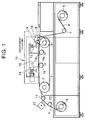
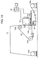
- Fig. 1 is a schematic sectional view of an ink jet printer to which the present invention is applied.
- an endless belt 1 is wound around and supported by a drive roller (drive rotary member) 2 and a driven roller (driven rotary member) 3.
- the drive roller 2 is connected to a drive motor so that, by controlling the drive motor, the drive roller 2 is rotated to intermittently shift the endless belt 1.
- the driven roller 3 is driven by the movement of the endless belt 1.
- a sheet (cloth web) 4 is wound around a take-out roll 5 and is wound up by a take-up roll 6. That is to say, the cloth web 4 unwound from the take-out roll 5 is passed through guide rollers 7, 8, and then is directed onto the endless belt 1 by an urging roller (urging rotary member) 9. Then, the cloth web is passed through a print area (to which a printer unit 10 is opposed) and guide rollers 11, 12 and is wound up by the take-up roll 6.
- a surface of the endless belt 1 is treated by an adhesive or the like so that, when the cloth web 4 is urged against the endless belt 1 by the urging roller 9, the cloth web 4 can be adhered to the surface of the endless belt 1, and, when the cloth web 4 adhered to the surface of the endless belt 1 is passed through a curvature portion of the drive roller 2 together with the endless belt 1, the cloth web 4 can easily be peeled from the endless belt 1.
- the printer unit 10 comprises a carriage 14 shiftable along guide rails 13 in a direction perpendicular to a cloth web conveying direction and an ink jet head 15 mounted on the carriage 14 in a confronting relation to the endless belt 1.
- the printer unit 10 itself can be shifted by means of a shifting means (not shown) in the cloth web conveying direction so that the cloth web 4 closely contacted with the endless belt 2 is scanned by the ink jet head 15.
- the ink jet head 15 used in the illustrated embodiment has nozzles within which heat generating elements are disposed.
- the desired heat generating element is energized to provide thermal energy, a bubble is created in the corresponding nozzle, and, as the bubble is expanded, ink droplet is discharged from the nozzle.
- a portion of the endless belt 1 is maintained in parallel with the ink jet head by a platen portion 16a defined by two platen rollers 16, so that the cloth web 4 adhered to the endless belt 1 is also maintained in parallel with the ink jet head.
- the endless belt 1 is stopped, the ink droplets are discharged from the ink jet head 15 while scanning the cloth web in a predetermined direction, thereby performing a desired printing operation.
- a portion of the cloth web 4 on which the image was printed is conveyed by the movement of the endless belt 1 in a downstream direction. Meanwhile, the cloth web is guided by the guide rollers 11, 12 to reach a drying heater 17, where the ink on the cloth web is dried. Thereafter, the cloth web is wound around the take-up roll 6.
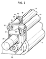
- FIG. 2 is a schematic perspective view showing an urging rotary member and therearound
- Fig. 3 is a plan view, in partial section, of the urging rotary member, a driven rotary member and therearound, looked at from an upstream side in the endless belt conveying direction
- Fig. 4 is a partial sectional view of the driven rotary member portion
- Fig. 5 is a partial sectional view of the urging rotary member portion
- Fig. 6 is a sectional view taken along the line A-A in Fig. 5, showing a rocking operation of a rocking member
- Fig. 2 is a schematic perspective view showing an urging rotary member and therearound
- Fig. 3 is a plan view, in partial section, of the urging rotary member, a driven rotary member and therearound, looked at from an upstream side in the endless belt conveying direction
- Fig. 4 is a partial sectional view of the driven rotary member portion
- Fig. 5 is a partial sectional view of the urging rotary member
- FIG. 7 is a sectional view taken along the line A-A in Fig. 5, showing a rocking angle of the urging rotary member
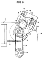
- Fig. 8 is an explanatory view showing a condition that the urging rotary member is urged against the endless belt
- Fig. 9 is an explanatory view showing a condition that an urging force of the urging rotary member is released
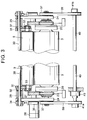
- Fig. 10 is an explanatory view showing a condition that the urging rotary member is separated from the endless belt
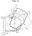
- Fig. 11 is an explanatory view showing an arrangement of sensors for detecting a position of the rock member.
- the driven roller 3 for mounting the endless belt 1 is rotatably mounted within the apparatus.
- the driven roller 3 is supported by bearings 22 held in bearing holders 21 attached to side plates 20.
- Driven roller spur wheels (gears) 23 are mounted on both ends of the driven roller 3 so that a rotational force of the driven roller 3 can be transmitted to the gears 23 through keys 23a.
- Rock arms 24 (acting as rock members pivotally supported around the driven roller 3) are pivotally mounted on both ends of the driven roller via bearings 25. A rocking movement of the rock arm 24 is effected by a rock arm driving motor 26 secured to the rock arm 24.
- Driving motor spur wheel (gear) 27 is mounted on a drive shaft of the rock arm driving motor 26 so that a power from the rock arm driving motor 26 is transmitted to the gear 27 through keys 28.
- the driven roller spur gear 23 and the driving motor spur gear 27 are meshed with each other, with the result that, when the rock arm driving motor 26 is operated and the power is transmitted to the spur gear 27, the spur gear 27 is revolved around the driven roller spur gear 23. Due to this revolution, the rock arms 24 are rocked around the driven roller 3.
- a transmission shaft 30 is rotatably supported by guide bushes 29 secured to the rock arms 24, and transmission clamp set collars 32 secured to urging roller attaching plates 31 are clamped on the transmission shaft 30. With this arrangement, a rotational force of the transmission shaft 30 is transmitted to the urging roller attaching plates 31 so that the plates 31 are rocked around a center of the transmission shaft 30.
- the urging roller 9 is rotatably supported by the urging roller attaching plates 31 via bearings 33. Further, at outer sides of the rock arms 24, transmission shaft clamp set collars 32 are secured to the transmission shaft 30, and the collars are also secured to urging roller driving arms 34.
- the urging roller driving arms 34, transmission shaft 30, urging roller attaching plates 31, rock arms 24 and the like constitute a support means for supporting the urging rotary member, and the rock arms 24, rock arm driving motor 26, driving motor spur gears 27, driven roller spur gears 23 and the like constitute drive means for driving the support means.
- a shifting means for shifting the urging rotary member relative to the endless belt at a constant relative speed is constituted by the support means, drive means, driven roller 3 and the like.
- the urging roller driving arms 34 are rocked or rotated together with the transmission shaft 30, and, thus, the rocking movement of the urging roller driving arms 34 is transmitted as the rotational movement of the transmission shaft 30. Further, there is provided urging cylinders (urging force applying means) 35 capable of abutting against one end of the urging roller driving arms 34 so that the urging force of the urging roller 9 is generated by the urging cylinders 35.
- the thrust forces of the cylinders are applied to the ends of the respective urging roller driving arms 34 to rotate the urging roller driving arms 34 together with the transmission shaft 30.
- the rotational force of the transmission shaft 30 is transmitted to the urging roller attaching plates 31 to rotate the urging roller attaching plates 31 together with the transmission shaft 30, thereby urging the urging roller 9 against the endless belt 1 supported by the driven roller 3.
- the urging force of the urging roller 9 urged against the endless belt 1 is adjusted by air pressure supplied to the urging cylinders 35.
- urging force releasing springs 36 each of which has one end attached to the corresponding urging roller driving arm 34 at a position between the portion connected to the transmission shaft 30 and the portion engaged by the urging cylinder 35 and the other end connected to the corresponding rock arm 24. Accordingly, when the urging cylinders are in a retracted condition, the urging roller driving arms 34 are always biased toward a direction shown by the arrow b in Fig. 2 by the spring forces of the urging force releasing springs 36, with the result that the urging roller 9 is spaced apart from the endless belt 1.
- Transmission pulleys 37 are secured on outer surfaces of the pair of the rock arms 24 via bolts disposed in alignment with the center line of the driven roller 3.
- the transmission pulleys 37 are connected, through timing belts 39, to a brake pulley 41a and a pulley 41b, respectively, which are provided on both ends of a rockable transmission shaft 40.
- a rotational movement of the brake pulley 41a is transmitted to the rockable transmission shaft 40 through keys 42 shown in Fig. 3.
- the rock arm driving motor 26 is attached to one of the rock arms 24, and the movement of this rock arm 24 is transmitted to the other rock arm 24 through the transmission pulley 37, timing belt 39, brake pulley 41a, transmission shaft 40, pulley 41b, timing belt 39 and transmission pulley 37, thereby rocking the rock arms in synchronous with each other.
- a brake which can be operated when the power is off to lock the rockable transmission shaft 40 to the apparatus (thereby stopping this transmission shaft) is provided on the rockable transmission shaft 40.
- the brake 43 is operated to lock the rockable transmission shaft 40, thereby preventing the rock arms 24 from lowering by their own weights.
- Figs. 6 and 7 show a rocking angle of the urging roller 9 (with respect to the endless belt 1 supported by the driven roller 3) held by the rock arms 24 rocked around the driven roller 3 by the engagement between the driving motor spur gear 27 and the driven roller spur gear 23.
- the rock arm 24 is controlled by the rock arm driving motor 26 in such a manner that the rock arm is rotated by an angle of ⁇ ° during one cycle of the driven roller.
- the driven roller spur gear 23 When the driven roller 3 is rotated, the driven roller spur gear 23 is also rotated accordingly. Therefore, although the rotational force of the gear 23 is transmitted to the driving motor spur gear 27, since the rock arm driving motor 26 has large torque sufficient to rock all of the rockable elements including the rock arms 24, urging roller 9, guide roller 8 and the like, even when the driven roller spur gear 23 is rotated due to the rotation of the driven roller 3, the rock arm driving motor 26 is not rotated idly. Accordingly, when the driven roller spur gear 23 is rotated due to the rotation of the driven roller 3, the rotational force of the gear 23 acts to lift the rock arms 24 (in a direction shown by the arrow c in Fig. 6). Further, also at this point, the rock arm driving motor 26 continues to rotate at a constant speed.
- Figs. 8 and 9 show extension and retraction of the urging cylinder 35.
- Fig. 8 shows a condition that the urging cylinder 35 is extended to urge the urging roller 9 against the endless belt 1. In this condition, the cloth web 4 can be directed to the endless belt 1 and be closely contacted with the endless belt.
- Fig. 9 shows a condition that the urging cylinder 35 is retracted to release the urging force of the urging roller 9 from the endless belt 1.
- the urging force releasing springs 36 comprise coil springs for releasing the urging force acting on the cloth web 4 due to the weights of the urging roller 9 and associated support elements themselves. By the action of the springs 36, it is possible to release the urging force without separating the urging roller 9 from the cloth web 4.
- the urging roller is always contacted with the endless belt 1, since the setting of the cloth web 4 becomes difficult, as shown in Fig. 10, by lowering the urging roller driving arm 34 by manipulating a lever 44 attached to the urging roller driving arm 34, the urging roller 9 can be separated from the endless belt 1.
- the urging roller driving arm 34 to which the lever 44 is to be attached is provided at its end with a hole into which the lever 44 can be inserted. Accordingly, after the lever 44 is inserted into the hole and then the urging roller driving arm 34 is lowered, by inserting a stopper 45 into a hole formed in the rock arm 24 at a predetermined position, the urging roller driving arm 34 can be maintained in a lowered position.
- Fig. 11 shows sensors for detecting the position of the rock arm 24.
- a home position sensor 46 serves to ascertain a home position (initial position) of the rock arm driving motor 26 and also acts as a sensor for ascertaining a start position of the rock arm 24.
- An overrun sensor 47 serves to regulate the position of the urging roller 9.
- the urging roller 9 When the driven roller 3 is rotated to return the rock arms 24 in the rotational direction of the driven roller 3, if the urging roller 9 is returned to a position exceeding its start position for any reason such as positional deviation, timing deviation or the like, the urging roller 9 will be urged against a portion of the endless belt 1 which is not directly supported by the driven roller 3. If such a condition occurs, excessive tension will be applied to the endless belt 1, which may be damaged. To avoid this, the position of the urging roller 9 is regulated by the overrun sensor 47. Immediately after a detection signal is emitted from the overrun sensor 47, the supplying of power to the rock arm driving motor 26 is interrupted, with the result that the output shaft of the rock arm driving motor 26 becomes a torque free condition. At the same time, the brake 43 is activated to stop the rock arms 24. In this case, if an abnormal signal is emitted, the urging cylinders are retracted, thereby releasing the urging force of the urging roller 9.
- the rock arms 24 are gradually deviated downwardly.
- the position of the rock arm 24 is regulated by an overrun sensor 48.
- the rock arm driving motor 26 is stopped.
- the torque of the output shaft of the rock arm driving motor 26 is kept as it is.
- the urging cylinders 35 are retracted to release the urging force of the urging roller 9.
- sensors may be provided at other positions.
- a detection dog may be provided on the brake pulley and such sensors may be disposed on such a dog.
- the sheet convey apparatus Since the sheet convey apparatus according to the present invention has the above-mentioned construction and function, it is possible to continuously drive the drive means for driving the support means supporting the urging rotary member, regardless of the intermittent movement or stoppage of the endless belt, with the result that any portion of the sheet can be closely contacted with the endless belt with the constant urging force. As a result, the sheet can be closely contacted with the endless belt without any streak.
- the sheet conveyed by the present invention may be a fabric web, paper sheet, resin film or the like, as well as the cloth web.
- a convey roller may be used as the convey means.
- the urging roller as the urging rotary member is supported in such a manner that the roller can be revolved around the convey roller.
- a sheet convey apparatus and a printer having such a sheet convey apparatus according to the present invention have rock arms (24) rockable around a rotational center of a driven roller (3) on which an endless belt (1) is supported.
- Urging roller attaching plates (31) for supporting the urging roller (9), a transmission shaft (30), urging roller driving arms (34) and urging cylinders (35) are attached to the rock arms (24), and the urging cylinders (35) can abut against the corresponding urging roller driving arms (34).
- Urging force releasing springs (36) are connected between the urging roller driving arms (34) and the rock arms (24).
Landscapes
- Engineering & Computer Science (AREA)
- Textile Engineering (AREA)
- Delivering By Means Of Belts And Rollers (AREA)
- Ink Jet (AREA)
- Advancing Webs (AREA)
- Treatment Of Fiber Materials (AREA)
- Handling Of Continuous Sheets Of Paper (AREA)
- Registering, Tensioning, Guiding Webs, And Rollers Therefor (AREA)
- Coloring (AREA)
Applications Claiming Priority (3)
| Application Number | Priority Date | Filing Date | Title |
|---|---|---|---|
| JP32229694A JP3285458B2 (ja) | 1994-12-26 | 1994-12-26 | シート搬送装置およびシート搬送装置を有するプリンタ |
| JP32229694 | 1994-12-26 | ||
| JP322296/94 | 1994-12-26 |
Publications (3)
| Publication Number | Publication Date |
|---|---|
| EP0719721A2 true EP0719721A2 (fr) | 1996-07-03 |
| EP0719721A3 EP0719721A3 (fr) | 1997-03-26 |
| EP0719721B1 EP0719721B1 (fr) | 2000-07-26 |
Family
ID=18142051
Family Applications (1)
| Application Number | Title | Priority Date | Filing Date |
|---|---|---|---|
| EP95120243A Expired - Lifetime EP0719721B1 (fr) | 1994-12-26 | 1995-12-21 | Appareil de transport de bande et imprimante équipée de celui-ci |
Country Status (6)
| Country | Link |
|---|---|
| US (1) | US5883654A (fr) |
| EP (1) | EP0719721B1 (fr) |
| JP (1) | JP3285458B2 (fr) |
| KR (1) | KR100203008B1 (fr) |
| CN (1) | CN1058227C (fr) |
| DE (1) | DE69518139T2 (fr) |
Cited By (3)
| Publication number | Priority date | Publication date | Assignee | Title |
|---|---|---|---|---|
| CN1064902C (zh) * | 1996-09-01 | 2001-04-25 | 华中理工大学 | 纸叠层快速成形机的送收纸机构 |
| EP1220754A1 (fr) * | 1999-09-20 | 2002-07-10 | Scanvec Garment Systems, Ltd. | Imprimante a mouvement synchronise, a deplacement de papier continu |
| EP1577101A2 (fr) * | 2004-03-17 | 2005-09-21 | Milini, Paolo | Procede et appareil d'impression des matériaux par jet d'encre, en particulier matériaux en forme de feuilles comme tissus, peaux ou similaires |
Families Citing this family (39)
| Publication number | Priority date | Publication date | Assignee | Title |
|---|---|---|---|---|
| US20020054781A1 (en) * | 2000-11-07 | 2002-05-09 | Aharon Korem | Method for environmentally-friendly textile transportation in printing systems and a system thereof cross-reference to related applications |
| US6857803B2 (en) | 2001-01-08 | 2005-02-22 | Vutek, Inc. | Printing system web guide with a removable platen |
| US6679640B2 (en) | 2001-01-08 | 2004-01-20 | Vutek, Incorporated | Printing system web guide coupling assembly |
| JP2008080526A (ja) * | 2006-09-26 | 2008-04-10 | Brother Ind Ltd | 液体噴射装置 |
| JP5157808B2 (ja) * | 2007-12-28 | 2013-03-06 | セイコーエプソン株式会社 | インクジェット捺染装置 |
| US9023063B2 (en) | 2008-04-17 | 2015-05-05 | Apollo Endosurgery, Inc. | Implantable access port device having a safety cap |
| EP2471572A3 (fr) | 2008-04-17 | 2012-10-17 | Allergan, Inc. | Dispositif de port d'accès implantable |
| US8708979B2 (en) | 2009-08-26 | 2014-04-29 | Apollo Endosurgery, Inc. | Implantable coupling device |
| US8506532B2 (en) * | 2009-08-26 | 2013-08-13 | Allergan, Inc. | System including access port and applicator tool |
| US8715158B2 (en) * | 2009-08-26 | 2014-05-06 | Apollo Endosurgery, Inc. | Implantable bottom exit port |
| US20110196195A1 (en) * | 2010-02-05 | 2011-08-11 | Allergan, Inc. | Implantable subcutaneous access port |
| US8882728B2 (en) * | 2010-02-10 | 2014-11-11 | Apollo Endosurgery, Inc. | Implantable injection port |
| US20110270021A1 (en) | 2010-04-30 | 2011-11-03 | Allergan, Inc. | Electronically enhanced access port for a fluid filled implant |
| US20110270025A1 (en) | 2010-04-30 | 2011-11-03 | Allergan, Inc. | Remotely powered remotely adjustable gastric band system |
| US8992415B2 (en) | 2010-04-30 | 2015-03-31 | Apollo Endosurgery, Inc. | Implantable device to protect tubing from puncture |
| US20120041258A1 (en) | 2010-08-16 | 2012-02-16 | Allergan, Inc. | Implantable access port system |
| CN102009534B (zh) * | 2010-09-07 | 2012-07-25 | 淄博兰雁集团有限责任公司 | 带有电子加速器机构的织物打印染色装置 |
| US20120065460A1 (en) | 2010-09-14 | 2012-03-15 | Greg Nitka | Implantable access port system |
| CN102059848B (zh) * | 2010-11-18 | 2012-10-31 | 江苏舒尔雅家纺有限公司 | 平网印花机生产流水线 |
| US8821373B2 (en) | 2011-05-10 | 2014-09-02 | Apollo Endosurgery, Inc. | Directionless (orientation independent) needle injection port |
| JP5875788B2 (ja) * | 2011-06-24 | 2016-03-02 | セーレン株式会社 | インクジェット記録装置及びインクジェット記録方法 |
| US8801597B2 (en) | 2011-08-25 | 2014-08-12 | Apollo Endosurgery, Inc. | Implantable access port with mesh attachment rivets |
| US9199069B2 (en) | 2011-10-20 | 2015-12-01 | Apollo Endosurgery, Inc. | Implantable injection port |
| US8858421B2 (en) | 2011-11-15 | 2014-10-14 | Apollo Endosurgery, Inc. | Interior needle stick guard stems for tubes |
| US9089395B2 (en) | 2011-11-16 | 2015-07-28 | Appolo Endosurgery, Inc. | Pre-loaded septum for use with an access port |
| CN103848252A (zh) * | 2012-12-06 | 2014-06-11 | 苏州宏瑞达新能源装备有限公司 | 一种eva牵引机构 |
| JP6264537B2 (ja) * | 2013-01-10 | 2018-01-24 | セイコーエプソン株式会社 | 記録装置及び記録方法 |
| JP6274399B2 (ja) * | 2013-01-10 | 2018-02-07 | セイコーエプソン株式会社 | 記録装置 |
| CN103909744A (zh) * | 2014-03-25 | 2014-07-09 | 绍兴县易彩数控喷墨技术研发有限公司 | 一种压布机构及压布方法 |
| CN103935806A (zh) * | 2014-04-16 | 2014-07-23 | 湖州巧布师数码科技有限公司 | 一种适用于印花发色机的布匹传送装置 |
| CN104386523A (zh) * | 2014-11-11 | 2015-03-04 | 南京协凯科技有限公司 | 一种用于pvb膜收卷的装置 |
| JP6703300B2 (ja) * | 2016-02-19 | 2020-06-03 | セイコーエプソン株式会社 | 記録装置 |
| JP2018187809A (ja) * | 2017-04-28 | 2018-11-29 | 株式会社ミマキエンジニアリング | 印刷装置 |
| CN107620180B (zh) * | 2017-11-02 | 2020-04-24 | 界首市永顺服饰有限公司 | 一种用于服装生产的布料印染装置 |
| CN109573672A (zh) * | 2018-05-31 | 2019-04-05 | 烟台知兴知识产权咨询服务有限公司 | 一种印彩包装用传送装置 |
| CN108910578A (zh) * | 2018-07-16 | 2018-11-30 | 佛山市特耐家纺实业有限公司 | 一种用于数码印花机的自动收卷装置 |
| CN109624493A (zh) * | 2018-12-06 | 2019-04-16 | 山东玫姿蓝家纺有限公司 | 一种毛毯加工用印花装置 |
| KR102507602B1 (ko) | 2021-12-27 | 2023-03-09 | (주)제이비 바이오 | 침향 고상발효산물과 그 용도 및 제조방법 |
| CN114368635B (zh) * | 2022-03-21 | 2022-06-10 | 广东合科泰实业有限公司 | 一种排片机轨道压轮力度自动调整装置 |
Citations (4)
| Publication number | Priority date | Publication date | Assignee | Title |
|---|---|---|---|---|
| FR1008816A (fr) * | 1950-01-10 | 1952-05-22 | Etudes De Machines Speciales | Dispositif pour le contrôle du déroulement et du mesurage d'une bande souple ou d'un fil |
| EP0305230A1 (fr) * | 1987-07-30 | 1989-03-01 | MACHINES CHAMBON Société anonyme dite: | Dispositif d'alimentation pour une machine travaillant sur une nappe de matériau à l'arrêt, notamment pour une presse à découper à plat |
| US4810006A (en) * | 1987-05-26 | 1989-03-07 | Katz Marcella M | Stabilized sheet materials for use with computer-directed printers and method of stabilizing same for computer printers |
| US5345863A (en) * | 1993-01-28 | 1994-09-13 | Kanebo Ltd. | Continuous web printing apparatus |
Family Cites Families (7)
| Publication number | Priority date | Publication date | Assignee | Title |
|---|---|---|---|---|
| JPS61155149A (ja) * | 1984-12-27 | 1986-07-14 | Sharp Corp | 駆動力の間欠伝達装置 |
| US4756788A (en) * | 1985-01-25 | 1988-07-12 | Allied-Signal Inc. | Inline winder with take-up web |
| JPS6350567A (ja) * | 1986-08-18 | 1988-03-03 | 山東エンジニアリング株式会社 | 帯状製品の連続クリ−ニング装置 |
| US5225853A (en) * | 1990-02-02 | 1993-07-06 | Canon Kabushiki Kaisha | Recording apparatus with conveyor cleaning mechanism |
| JPH0551637A (ja) * | 1991-08-22 | 1993-03-02 | Nkk Corp | 高強度鉄筋用鋼の製造方法 |
| US5485190A (en) * | 1993-05-20 | 1996-01-16 | Eastman Kodak Company | Printhead writer assembly engageable with a web image member |
| JP2809082B2 (ja) * | 1993-12-29 | 1998-10-08 | 日本電気株式会社 | 熱転写カラープリンタ |
-
1994
- 1994-12-26 JP JP32229694A patent/JP3285458B2/ja not_active Expired - Fee Related
-
1995
- 1995-12-21 EP EP95120243A patent/EP0719721B1/fr not_active Expired - Lifetime
- 1995-12-21 US US08/576,335 patent/US5883654A/en not_active Expired - Fee Related
- 1995-12-21 DE DE69518139T patent/DE69518139T2/de not_active Expired - Fee Related
- 1995-12-23 KR KR1019950055608A patent/KR100203008B1/ko not_active IP Right Cessation
- 1995-12-26 CN CN95120172A patent/CN1058227C/zh not_active Expired - Fee Related
Patent Citations (4)
| Publication number | Priority date | Publication date | Assignee | Title |
|---|---|---|---|---|
| FR1008816A (fr) * | 1950-01-10 | 1952-05-22 | Etudes De Machines Speciales | Dispositif pour le contrôle du déroulement et du mesurage d'une bande souple ou d'un fil |
| US4810006A (en) * | 1987-05-26 | 1989-03-07 | Katz Marcella M | Stabilized sheet materials for use with computer-directed printers and method of stabilizing same for computer printers |
| EP0305230A1 (fr) * | 1987-07-30 | 1989-03-01 | MACHINES CHAMBON Société anonyme dite: | Dispositif d'alimentation pour une machine travaillant sur une nappe de matériau à l'arrêt, notamment pour une presse à découper à plat |
| US5345863A (en) * | 1993-01-28 | 1994-09-13 | Kanebo Ltd. | Continuous web printing apparatus |
Non-Patent Citations (1)
| Title |
|---|
| DATABASE WPI Derwent Publications Ltd., London, GB; AN 88-101372 XP002023363 & JP-A-63 050 567 (SANTO ENG. K.K.) , 30 March 1988 * |
Cited By (5)
| Publication number | Priority date | Publication date | Assignee | Title |
|---|---|---|---|---|
| CN1064902C (zh) * | 1996-09-01 | 2001-04-25 | 华中理工大学 | 纸叠层快速成形机的送收纸机构 |
| EP1220754A1 (fr) * | 1999-09-20 | 2002-07-10 | Scanvec Garment Systems, Ltd. | Imprimante a mouvement synchronise, a deplacement de papier continu |
| EP1220754A4 (fr) * | 1999-09-20 | 2007-07-25 | Peter Hasiuk | Imprimante a mouvement synchronise, a deplacement de papier continu |
| EP1577101A2 (fr) * | 2004-03-17 | 2005-09-21 | Milini, Paolo | Procede et appareil d'impression des matériaux par jet d'encre, en particulier matériaux en forme de feuilles comme tissus, peaux ou similaires |
| EP1577101A3 (fr) * | 2004-03-17 | 2007-05-23 | Milini, Paolo | Procede et appareil d'impression des matériaux par jet d'encre, en particulier matériaux en forme de feuilles comme tissus, peaux ou similaires |
Also Published As
| Publication number | Publication date |
|---|---|
| JP3285458B2 (ja) | 2002-05-27 |
| CN1058227C (zh) | 2000-11-08 |
| DE69518139D1 (de) | 2000-08-31 |
| US5883654A (en) | 1999-03-16 |
| EP0719721B1 (fr) | 2000-07-26 |
| JPH08175716A (ja) | 1996-07-09 |
| KR100203008B1 (ko) | 1999-06-15 |
| KR960021535A (ko) | 1996-07-18 |
| EP0719721A3 (fr) | 1997-03-26 |
| CN1133917A (zh) | 1996-10-23 |
| DE69518139T2 (de) | 2001-03-22 |
Similar Documents
| Publication | Publication Date | Title |
|---|---|---|
| EP0719721B1 (fr) | Appareil de transport de bande et imprimante équipée de celui-ci | |
| US5825374A (en) | Apparatus and method for advancing a web | |
| EP1980399B1 (fr) | Mécanisme pour élément de transfert doté d'un mouvement de course à vide | |
| US5764264A (en) | Image forming apparatus having a movable separator for separating a recording medium from a feeding belt | |
| KR960012779B1 (ko) | 인자장치의 카아본 리본 헐거움 방지기구 | |
| KR0166427B1 (ko) | 프린터 및 용지를 인자부로 공급하는 방법 | |
| EP0765221B1 (fr) | Procede d'impression | |
| JPH06345284A (ja) | ベルト搬送装置及びこれを用いた中間転写型インクジェット記録装置 | |
| EP0157096B1 (fr) | Mécanisme pour enrouler des rubans | |
| JP2635179B2 (ja) | 熱転写記録装置及び熱転写記録方法 | |
| US5816719A (en) | Printer for printing on a continuous print medium | |
| US4838719A (en) | Sheet tensioning printer rollers | |
| EP1710087A2 (fr) | Procédé d'impression utilisant un dispositif d'impression ayant une tête d'impression | |
| KR0166459B1 (ko) | 열전사식 프린터 | |
| JPH08152917A (ja) | 搬送装置 | |
| JP2964868B2 (ja) | 熱転写カードプリンタ | |
| EP0599217B1 (fr) | Imprimante à jet d'encre du type transfert | |
| JP2003048646A (ja) | 記録媒体の供給装置 | |
| JP4458443B2 (ja) | 記録装置 | |
| JP3181539B2 (ja) | インクジェット捺染装置 | |
| JP2024068551A (ja) | 歯車機構、張力制御装置及び画像形成装置 | |
| JPH0383668A (ja) | サーマルプリンタ装置 | |
| JP2002002038A (ja) | プリンタ装置 | |
| JPH07156373A (ja) | インクジェット記録装置 | |
| JPH11147338A (ja) | 印刷装置 |
Legal Events
| Date | Code | Title | Description |
|---|---|---|---|
| PUAI | Public reference made under article 153(3) epc to a published international application that has entered the european phase |
Free format text: ORIGINAL CODE: 0009012 |
|
| AK | Designated contracting states |
Kind code of ref document: A2 Designated state(s): DE FR GB IT |
|
| PUAL | Search report despatched |
Free format text: ORIGINAL CODE: 0009013 |
|
| AK | Designated contracting states |
Kind code of ref document: A3 Designated state(s): DE FR GB IT |
|
| 17P | Request for examination filed |
Effective date: 19970812 |
|
| 17Q | First examination report despatched |
Effective date: 19971110 |
|
| GRAG | Despatch of communication of intention to grant |
Free format text: ORIGINAL CODE: EPIDOS AGRA |
|
| GRAG | Despatch of communication of intention to grant |
Free format text: ORIGINAL CODE: EPIDOS AGRA |
|
| GRAH | Despatch of communication of intention to grant a patent |
Free format text: ORIGINAL CODE: EPIDOS IGRA |
|
| GRAH | Despatch of communication of intention to grant a patent |
Free format text: ORIGINAL CODE: EPIDOS IGRA |
|
| GRAA | (expected) grant |
Free format text: ORIGINAL CODE: 0009210 |
|
| AK | Designated contracting states |
Kind code of ref document: B1 Designated state(s): DE FR GB IT |
|
| REF | Corresponds to: |
Ref document number: 69518139 Country of ref document: DE Date of ref document: 20000831 |
|
| ITF | It: translation for a ep patent filed | ||
| ET | Fr: translation filed | ||
| PLBE | No opposition filed within time limit |
Free format text: ORIGINAL CODE: 0009261 |
|
| STAA | Information on the status of an ep patent application or granted ep patent |
Free format text: STATUS: NO OPPOSITION FILED WITHIN TIME LIMIT |
|
| 26N | No opposition filed | ||
| REG | Reference to a national code |
Ref country code: GB Ref legal event code: IF02 |
|
| PGFP | Annual fee paid to national office [announced via postgrant information from national office to epo] |
Ref country code: FR Payment date: 20051208 Year of fee payment: 11 |
|
| PGFP | Annual fee paid to national office [announced via postgrant information from national office to epo] |
Ref country code: DE Payment date: 20051215 Year of fee payment: 11 |
|
| PGFP | Annual fee paid to national office [announced via postgrant information from national office to epo] |
Ref country code: GB Payment date: 20051221 Year of fee payment: 11 |
|
| PGFP | Annual fee paid to national office [announced via postgrant information from national office to epo] |
Ref country code: IT Payment date: 20061231 Year of fee payment: 12 |
|
| PG25 | Lapsed in a contracting state [announced via postgrant information from national office to epo] |
Ref country code: DE Free format text: LAPSE BECAUSE OF NON-PAYMENT OF DUE FEES Effective date: 20070703 |
|
| GBPC | Gb: european patent ceased through non-payment of renewal fee |
Effective date: 20061221 |
|
| REG | Reference to a national code |
Ref country code: FR Ref legal event code: ST Effective date: 20070831 |
|
| PG25 | Lapsed in a contracting state [announced via postgrant information from national office to epo] |
Ref country code: GB Free format text: LAPSE BECAUSE OF NON-PAYMENT OF DUE FEES Effective date: 20061221 |
|
| PG25 | Lapsed in a contracting state [announced via postgrant information from national office to epo] |
Ref country code: FR Free format text: LAPSE BECAUSE OF NON-PAYMENT OF DUE FEES Effective date: 20070102 |
|
| PG25 | Lapsed in a contracting state [announced via postgrant information from national office to epo] |
Ref country code: IT Free format text: LAPSE BECAUSE OF NON-PAYMENT OF DUE FEES Effective date: 20071221 |