EP0719077B1 - Verfahren und Vorrichtung zur Bestimmung der absoluten Plasmaparameter - Google Patents
Verfahren und Vorrichtung zur Bestimmung der absoluten Plasmaparameter Download PDFInfo
- Publication number
- EP0719077B1 EP0719077B1 EP95119294A EP95119294A EP0719077B1 EP 0719077 B1 EP0719077 B1 EP 0719077B1 EP 95119294 A EP95119294 A EP 95119294A EP 95119294 A EP95119294 A EP 95119294A EP 0719077 B1 EP0719077 B1 EP 0719077B1
- Authority
- EP
- European Patent Office
- Prior art keywords
- electrode
- reactor
- plasma
- discharge current
- ofthe
- Prior art date
- Legal status (The legal status is an assumption and is not a legal conclusion. Google has not performed a legal analysis and makes no representation as to the accuracy of the status listed.)
- Expired - Lifetime
Links
- 238000000034 method Methods 0.000 title claims abstract description 39
- 210000002381 plasma Anatomy 0.000 claims abstract description 101
- 239000004020 conductor Substances 0.000 claims description 52
- 239000000523 sample Substances 0.000 claims description 46
- 230000010355 oscillation Effects 0.000 claims description 24
- 230000005284 excitation Effects 0.000 claims description 19
- 238000009413 insulation Methods 0.000 claims description 12
- 238000005259 measurement Methods 0.000 claims description 8
- 230000005684 electric field Effects 0.000 claims description 6
- 230000007935 neutral effect Effects 0.000 claims description 6
- 239000002245 particle Substances 0.000 claims description 6
- 238000013016 damping Methods 0.000 claims description 5
- 238000013459 approach Methods 0.000 claims description 4
- 238000010276 construction Methods 0.000 claims description 4
- 238000010292 electrical insulation Methods 0.000 claims description 3
- 230000002093 peripheral effect Effects 0.000 claims description 3
- 238000005192 partition Methods 0.000 claims 3
- 238000001020 plasma etching Methods 0.000 abstract description 5
- 239000004065 semiconductor Substances 0.000 abstract description 4
- 238000005516 engineering process Methods 0.000 abstract description 3
- 208000028659 discharge Diseases 0.000 description 52
- 150000002500 ions Chemical class 0.000 description 18
- 239000007789 gas Substances 0.000 description 13
- 230000008569 process Effects 0.000 description 7
- 238000012545 processing Methods 0.000 description 6
- 238000001228 spectrum Methods 0.000 description 5
- 230000008901 benefit Effects 0.000 description 4
- 238000006073 displacement reaction Methods 0.000 description 4
- 239000003574 free electron Substances 0.000 description 4
- 238000009825 accumulation Methods 0.000 description 3
- 230000035508 accumulation Effects 0.000 description 3
- 230000009022 nonlinear effect Effects 0.000 description 3
- 238000007789 sealing Methods 0.000 description 3
- XKRFYHLGVUSROY-UHFFFAOYSA-N Argon Chemical compound [Ar] XKRFYHLGVUSROY-UHFFFAOYSA-N 0.000 description 2
- 239000004809 Teflon Substances 0.000 description 2
- 229920006362 Teflon® Polymers 0.000 description 2
- 230000005540 biological transmission Effects 0.000 description 2
- 238000010586 diagram Methods 0.000 description 2
- 238000005530 etching Methods 0.000 description 2
- 239000000463 material Substances 0.000 description 2
- 230000003287 optical effect Effects 0.000 description 2
- 238000005334 plasma enhanced chemical vapour deposition Methods 0.000 description 2
- 238000000623 plasma-assisted chemical vapour deposition Methods 0.000 description 2
- 230000035945 sensitivity Effects 0.000 description 2
- 238000010521 absorption reaction Methods 0.000 description 1
- 229910052786 argon Inorganic materials 0.000 description 1
- 239000002800 charge carrier Substances 0.000 description 1
- 238000000151 deposition Methods 0.000 description 1
- 230000008021 deposition Effects 0.000 description 1
- 238000009795 derivation Methods 0.000 description 1
- 230000000694 effects Effects 0.000 description 1
- 238000004993 emission spectroscopy Methods 0.000 description 1
- 230000007613 environmental effect Effects 0.000 description 1
- 230000004907 flux Effects 0.000 description 1
- 239000001307 helium Substances 0.000 description 1
- 229910052734 helium Inorganic materials 0.000 description 1
- SWQJXJOGLNCZEY-UHFFFAOYSA-N helium atom Chemical compound [He] SWQJXJOGLNCZEY-UHFFFAOYSA-N 0.000 description 1
- 238000011065 in-situ storage Methods 0.000 description 1
- 238000005305 interferometry Methods 0.000 description 1
- 238000004949 mass spectrometry Methods 0.000 description 1
- 238000013178 mathematical model Methods 0.000 description 1
- 230000003071 parasitic effect Effects 0.000 description 1
- 229920001343 polytetrafluoroethylene Polymers 0.000 description 1
- 239000004810 polytetrafluoroethylene Substances 0.000 description 1
- 238000011160 research Methods 0.000 description 1
- 230000004044 response Effects 0.000 description 1
- 238000000926 separation method Methods 0.000 description 1
- 239000007787 solid Substances 0.000 description 1
- 238000003860 storage Methods 0.000 description 1
- 239000000758 substrate Substances 0.000 description 1
- 230000002123 temporal effect Effects 0.000 description 1
- 238000012360 testing method Methods 0.000 description 1
- 230000009466 transformation Effects 0.000 description 1
- 238000000844 transformation Methods 0.000 description 1
- 235000012431 wafers Nutrition 0.000 description 1
Images

Classifications
-
- H—ELECTRICITY
- H01—ELECTRIC ELEMENTS
- H01J—ELECTRIC DISCHARGE TUBES OR DISCHARGE LAMPS
- H01J37/00—Discharge tubes with provision for introducing objects or material to be exposed to the discharge, e.g. for the purpose of examination or processing thereof
- H01J37/32—Gas-filled discharge tubes
- H01J37/32917—Plasma diagnostics
- H01J37/32935—Monitoring and controlling tubes by information coming from the object and/or discharge
-
- H—ELECTRICITY
- H05—ELECTRIC TECHNIQUES NOT OTHERWISE PROVIDED FOR
- H05H—PLASMA TECHNIQUE; PRODUCTION OF ACCELERATED ELECTRICALLY-CHARGED PARTICLES OR OF NEUTRONS; PRODUCTION OR ACCELERATION OF NEUTRAL MOLECULAR OR ATOMIC BEAMS
- H05H1/00—Generating plasma; Handling plasma
- H05H1/0006—Investigating plasma, e.g. measuring the degree of ionisation or the electron temperature
- H05H1/0012—Investigating plasma, e.g. measuring the degree of ionisation or the electron temperature using electromagnetic or particle radiation, e.g. interferometry
- H05H1/0062—Investigating plasma, e.g. measuring the degree of ionisation or the electron temperature using electromagnetic or particle radiation, e.g. interferometry by using microwaves
-
- H—ELECTRICITY
- H05—ELECTRIC TECHNIQUES NOT OTHERWISE PROVIDED FOR
- H05H—PLASMA TECHNIQUE; PRODUCTION OF ACCELERATED ELECTRICALLY-CHARGED PARTICLES OR OF NEUTRONS; PRODUCTION OR ACCELERATION OF NEUTRAL MOLECULAR OR ATOMIC BEAMS
- H05H1/00—Generating plasma; Handling plasma
- H05H1/0006—Investigating plasma, e.g. measuring the degree of ionisation or the electron temperature
- H05H1/0081—Investigating plasma, e.g. measuring the degree of ionisation or the electron temperature by electric means
Definitions
- the invention relates to a method for the determination of absolute plasma parameters of unsymmetrical radio frequency (RF) low-pressure plasmas.
- the invention further relates to an apparatus for the measurement of the radio frequency discharge current at a portion of a plasma reactor acting as ground electrode or earth electrode.
- RF radio frequency
- plasma is that of a ionized gas.
- a gas molecule is ionized, i e. a gas molecule is split up into a free electron and a positive ion (ionized molecule).
- This process often is an electron collision ionization.
- the feeding of a radio frequency alternating electric field leads to an accumulation of energy with respect to the electrons for an inelastic collision.
- the electrons impinge on other gas molecules which are again split up as mentioned before into free electrons and positive ions.
- a plasma state is formed in the entire reactor by this process. Electrons and ions recombine on the wall since the charge carrier, namely the free electrons and the positive ions, discharge to the walls of the reactor.
- a gas molecule is again formed so that an equilibrium is finally established in the reactor.
- the radio frequency alternating electric field is generated in the plasma reactor by means of parallel-plates wherein an excited or driven radio frequency (RF) electrode is positioned opposite to an earth electrode.
- the RF electrode is also called “hot electrode”.
- the real electrode which electrically forms the earth or ground, which is directly opposed to the RF electrode and which also includes portions of the reactor wall acting as earth, is called “earth electrode”.
- the electrodes of the plasma reactor are normally arranged in a horizontal manner. The RF electrode extends close and in parallel to the bottom wall or to the top wall ofthe reactor.
- a plasma having an excitation frequency between 10 and 100 MHz and a pressure of 0.1 to 100 Pa, preferably 0.1 to 20 Pa is called RF low-pressure plasma. Therefore, the gas is held under a predetermined constant pressure (vacuum) in the reactor. It is also possible to continuously feed the gas into the reactor and to continuously discharge the gas from the reactor.
- PE plasma etching
- RIE reactive ion etching
- PECVD plasma enhanced chemical vapour deposition
- the optical methods are above all characterized by emission spectrometric methods wherein the emission may partly be externally excited.
- This method has the advantage that the test object is influenced in a hardly observable manner; this method however has the disadvantage that only relative measuring results can normally be achieved.
- Mass spectrometric methods enable the determination of the relative intensity or further the mass selective determination of the ion energy distribution.
- the determination of absolute values for the particle density or for the current density is normally not possible by reason of the small aperture angle and the non-constant transmission.
- the determination of local plasma parameters, for example the electron density, the ion density and the electron energy may be achieved by means of Langmuir probes. Langmuir probes are however only applicable with respect to reactive or layer forming plasmas in a very limited manner.
- Integral plasma parameters may be determined by means of microwave interferometry.
- the frequency of the microwaves is above the local electron plasma frequency in order to enable the wave propagation in the plasma.
- This method normally needs a rigid reference line (in form of a hollow conductor).
- This method is not very flexible.
- the knowledge of the spatial distribution of the density of the electrons is necessary for an exact determination of the average density of the electrons.
- the spatial distribution of the density of the electrons is additionally to be determined for example by means of a Langmuir probe.
- Integral plasma parameters may however also be determined by means of resonance probes. These probes use the capability of forming resonances of the plasma including its boundary layers with respect to surrounding solids.
- the plasma resonance frequency which may also be called geometric plasma resonance frequency, is always slightly lower than the electron plasma frequency.
- Resonance probes may not be used with respect to RF discharges since the discharge itself generates a wide spectrum of harmonic oscillations and thus superimposes the response of the external excitation via the resonance probe.
- a radio-frequency (RF) driven probe method for RF discharge plasma diagnostics is described. It is disclosed an electrostatic probe technique for RF plasmas. The presence of RF potential fluctuations between probe and plasma distorts the Langmuir probe characteristic; it therefore introduces large errors into plasma parameters.
- the new method is an improved version of that proposed by Braithwaite et al to remove the effect of an RF fluctuation on probe characteristics. It consists in superimposing the fluctuation of the space potential measured by an emissive probe to the direct-current (DC) voltage applied to the probe.
- This technique is applied to the measurement of electron temperature and density in 13.56 MHz RF discharges in helium and argon.
- the electron temperature in the RF plasmas is higher than that in the equivalent DC plasmas and the electron density in the RF plasmas is lower than that in the equivalent DC plasmas.
- the present invention is based on a radio frequency measuring system which is insensitive with respect to thin but generally optical dense layers so that the method according to the present invention is relatively insensitive with respect to dirt accumulations, layers of materials and with respect to reactive materials.
- the method ensures a high stability over a long time and a good reliability and reproducibility of the absolute plasma parameters determined by the method according to the present invention.
- At least one resonance frequency of the discharge is determined from how the discharge current is timely developping.
- the resonance frequency according to the present invention is not the electron plasma frequency (Langmuir frequency) which describes the resonance in the plasma itself without participation of the boundary layers (space charge sheathes). This resonance frequency however indicates a geometric resonance being one geometry factor lower than the real plasma frequency. The geometric resonance is distinctly marked with respect to a strong unsymmetrical RF discharge. It is advantageous that a forced, i. e. external, excitation is not necessary because of the self excitation.
- the ion energy distribution in the harmonic oscillation in front of the RF electrode is determined from how the discharge current is timely developping wherein the measured discharge current forms a portion independent from the frequency of the entire discharge current and wherein this portion is preferably estimated by means of the area ratios of the part of the reactor acting as earth electrode and the RF electrode. It is advantageous that the average ion energy of the ions during impinging on the surface of the electrodes may be determined from the determined ion density distribution if the temporaryly averaged potential difference between the plasma and the RF electrode is known.
- the average ion energy is an important parameter of the process during treating of a substrate, for example a semiconductor plate, which is positioned on the RF electrode.
- the damping constant of the system which is dampedly oscillating because of the collision of the electrons with neutral particles of the plasma is determined from how the discharge current is timely developping.
- An effective electron-collision rate (also called effective electron collision frequency) may also be determined from the damping constant, said rate being a measure for the collisions of the electrons with the neutral particles of the plasma.
- the potential fed to the RF electrode or at least the dc part (direct current part) thereof is additionally required for the determination of the absolute value of the average thickness of the space charge sheath in front of the RF electrode and/or for the determination of the average ion energy.
- the meter electrode enables the measurement of the discharge current at the wall of the reactor wherein the meter electrode forms a virtual portion of the wall.
- the RF potential at the meter electrode shall be sufficient small with respect to the potential between plasma and meter electrode.
- the predescribed RF potential is between about 5 and 100 mV, preferably between 10 and 20 mV.
- the RF potential is thus several orders of magnitude below the plasma potential and its RF part.
- the meter electrode is fixed at the reactor by means of an electrically insulated vacuum feedthrough.
- the meter electrode comprises a rod shaped electrical conductor which is connected to ground outside the reactor.
- the electrical conductor is connected with a current transformer which generates a voltage from the measured current.
- This embodiment represents the first embodiment of the apparatus according to the present invention which has a simple construction and by which usual commercial vacuum feedthroughs may be used. Because of the possible great surface of electrodes, this meter electrode has a relatively high sensitivity.
- a probe which is fixed at the reactor by means of an electrically insulated vacuum feedthrough, which probe comprises an inner conductor connected with the meter electrode, an insulating body circumferentially surrounding the inner conductor, the insulation of the meter electrode and which probe comprises an outer conductor connected with the reactor wall.
- the outer conductor should preferably be provided within the flange, but as close as possible to the inner side of the reactor wall.
- This probe represents the second embodiment of the apparatus according to the present invention. It is further advantageous that such a probe has a high bandwidth with respect to the frequency to be measured. This bandwidth starts from the excitation frequency of the plasma, for example from 13.56 MHz, and goes further than the geometric plasma resonance frequency so that it is possible to measure the discharge current with a frequency of more than 300 MHz up to about 500 MHz.
- the vacuum feedthrough of the predescribed second embodiment of the apparatus according to the present invention is provided at both sides with a coaxial connection which is connectable to a corresponding counterconnection which is connected to the inner conductor, the insulating body and the outer conductor.
- a coaxial connection which is connectable to a corresponding counterconnection which is connected to the inner conductor, the insulating body and the outer conductor.
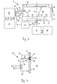
- FIG. 3 An apparatus 1 for determining absolute plasma parameters of unsymmetrical radio frequency (RF) low-pressure plasmas is schematically shown in Fig. 3.
- RF radio frequency
- An electrode 3 is located in a reactor 2, which is called plasma reactor in the following.
- the electrode 3 horizontally extends in parallel to the top wall 4 of the reactor 2 and a certain distance apart from said top wall.
- the electrode 3 is electrically connected to the top wall.
- the reactor 2 further comprises side walls 5, 6 which are connected with the top wall 4 on the one hand and which are connected to the bottom wall 7 on the other hand.
- the radio frequency (RF) electrode 10 extends close to the bottom wall 7 and in parallel thereto in horizontal direction.
- the electrode 10 is electrically connected by a conductor 11 with an accommodating network 12 and by a further conductor 13 with a generator 14.
- the generator 14 generates a voltage having a sinusoidal course.
- the conductor 11 comprises an insulation 15 at least in the region of its leadthrough through the bottom wall 7 so that the RF electrode 10 and the connector 11 are not electrically connected to the bottom wall 7.
- the electrode 3 including the walls 4, 5, 6 and 7 of the reactor 2 is designated as earth electrode in the following.
- the plasma 17 is located in the region 16 between the RF electrode 10 and the electrode 3. It is emphasized that in Fig. 3 region 16 is shown in the form of straight lines only for drawing purposes.
- a probe 20 is mounted on the side wall 5. By means of this probe, a part of the radio frequency discharge current, namely the part of the current which impinges on meter electrode 21 located in side wall 5, is measured.
- the probe 20 is connected to an analog/digital (A/D) converter 22, for example a digital storage oscilloscope.
- A/D converter 22 is connected to a data processing device 23, for example a personal computer.
- the analog signals measured by the probe 20 reach the A/D converter 22 via the conductor 24, which converter 22 converts the analog signals (data) into digital signals and which send the digital signals via the conductor 25 to the data processing device 23.
- the control of the A/D converter 22 is effected via conductor 26 by means of the data processing device 23.
- the conductor 11 connecting the accommodating network 12 with the RF electrode 10 is connected via a voltage divider 27, preferably a probe, with the A/D converter 22 by means of the conductor 30.
- a portion of the radio frequency discharge current namely the portion of the discharge current which impinges on the meter electrode 21, is measured by means of the meter electrode 21 of probe 20.
- this measured portion of the discharge current I p is shown versus the normalized time.
- Fig. 1 shows the electrode potential U versus the normalized time, said potential being fed to RF electrode 10 and electrode 3.
- Fig. 1 shows a saw-tooth course together with superimposed oscillations of the measured discharge current over the normalized time.
- Such a course has the meaning that within the period of one oscillation first of all a steep rise and in the following a gradual drop of the measured current takes place.
- This saw-tooth course is the result of nonlinear distortions because of the nonlinearity of the space charge sheath 33 in front of the RF electrode 10 (in Fig. 3 above the RF electrode 10).
- harmonic oscillations are generated in the discharge current. Since the thickness of the space charge sheath is dependant on the potential difference between the plasma and the RF electrode the space charge sheath acts as a nonlinear capacity. The nonlinear effect of the space charge sheath is considerably affected by the ion density distribution in the space charge sheath in front of the RF electrode 10.
- the electrode potential U shown in Fig. 1 versus the normalized time indicates a course which is nearly a sinusoidal oscillation. For purposes of a better understanding, this nearly sinusoidal course is indicated in Fig. 1 by dotted lines.
- the discharge consisting of the plasma body and of the space charge sheathes represents an oscillating system by reason of the inert mass of the electrons and the restoring force with respect to the electrical fields in the space charge sheathes between the plasma and the earth electrode on the one side and between the plasma and the RF electrode on the other side.
- the natural frequency of the oscillating system is below the electron plasma frequency (also called Langmuir frequency).
- the system is damped by the collisions of the electrons with the neutral particles of the gas so that finally a damped oscillation is performed.
- the plasma is self-excited to oscillations which are distinct adjacent to the resonance frequency.
- Fig. 2 a discrete spectrum of the measured values is shown.
- the measured discharge current shown in the Fourier spectrum of Fig. 2 indicates a maximum approximately in the region of the 10th to 11th harmonic oscillation. Since in Fig. 2 the Fourier spectrum is shown above the normalized frequency ⁇ / ⁇ 0 it follows that the resonance frequency ⁇ r is about 10 times greater than the excitation frequency ⁇ 0 . It is emphasized that the predescribed resonance frequency does not correspond with the electron plasma frequency ⁇ pe .
- the predescribed self-excitation of the system is distinct in case of a strongly unsymmetrical radio frequency discharge. During such a discharge, the space charge sheath 33 in front of RF-electrode 10 is the most important. Thus, the space charge sheath in front of the earth electrode can be neglected. Since the self-excitation extends at least up to the 10th harmonic oscillation any external excitation of the system is not necessary.
- the radio frequency discharge current is measured in the form of analog signals by means of the meter electrode 21 of the probe 20 at a part of reactor 2 acting as earth electrode.
- the radio frequency discharge current is passed via the conductor 24 to the A/D converter 22.
- the measured analog signals are converted into digital signals.
- the latter are passed via the conductor 25 to the data processing device 23.
- the plasma parameters are evaluated by means of a mathematical algorithm from the signals leaving the A/D converter.
- the mathematical algorithm is based on a suitable representation of the voltage drop over the space charge sheath in front of the RF electrode according to the displacement flux at the surface of the electrode in the differential equation describing the system.
- the latter also takes into account the inert mass of the electrons, their collisions with the neutral particles of the gas and the ion current to the wall (earth electrode) or to the RF electrode.
- the set of parameters comprising the parameters to be determined may be obtained by means of algebraic transformations.
- the inert mass of the electron can be treated as an inductance and the collisions with neutrals, including power absorption in the expanding sheath, as a resistance.
- the sheath acts as a nonlinear capacitance. Therefore the plasma can be regarded as a damped serial oscillation circuit.
- the nonlinear sheath capacitance excites the plasma by providing harmonic oscillations to damped oscillations close to the geometric resonance frequency, which is below the plasma frequency (Langmuir frequency).
- ⁇ 0 1 - ⁇ e 2 ⁇ ( ⁇ - j ⁇ )
- ⁇ e 2 e 2 n ⁇ 0 m e
- ⁇ 0 the permittivity [As/(Vm)] of the free space (vacuum)
- ⁇ e is the (electron) plasma frequency [1/s]
- ⁇ is the collision frequency [1/s]
- e is the elementary charge [As]
- n is the electron plasma density [1/m 3 ]
- m e is the electron mass [kg].
- Equation (2) For vanishing collision frequency ⁇ equation (2) is called the ECCLES relation.
- the unknown coefficients can be determined.
- the electron plasma density, the collision frequency, the plasma resistance and the power dissipated in the plasma body may be calculated.
- the predescribed at least one resonance frequency may be determined from how the measured discharge current is timely developping, the discharge being self-excited on said resonance frequency by harmonic oscillations in the discharge current which are generated by reason of the nonlinearity of the space charge sheath in front of the RF electrode.
- Several resonance frequencies may appear because of two-dimensional components of the current conduction (each streamline 31 in Fig. 3 has an axial and a radial component) and the nonlinearity of the space charge sheath. Only one resonance frequency is obtained at higher pressures.
- the ion density distribution in the harmonic oscillation in front of RF electrode may be determined from how the discharge current is timely developping, wherein the measured discharge current forms a portion of the entire discharge current, said portion being independent of the frequency.
- This frequency-independent portion of the entire discharge current is estimated in a first approach by the area ratios of the part of the reactor acting as earth electrode and the RF electrode. With respect to the mathematical model, his portion may also be estimated by the determination of the current dividing factor and the thickness of the electrical space charge sheath in front of the RF electrode. Moreover, the damping constant of the dampedly oscillating system may be determined from how the discharge current is timely developping. Insofar the potential being fed to the RF electrode or at least the dc part thereof is additionally measured for example at a location 34 outside from reactor 2 in Fig. 3, the absolute value of the average thickness of the space charge sheath in front of the RF electrode and the average ion energy may additionally be determined.
- important plasma parameters may be determined in absolute values which definitely characterise the operating conditions in the reactor.
- One of the important plasma parameters the electron density averaged over the volume, may easily be determined from the electron plasma frequency (also called Langmuir frequency) or directly from the geometric resonance frequency.
- the electron plasma frequency also called Langmuir frequency
- conclusions may be drawn regarding the state of the plasma and the real case of application, for example an etching process of semiconductor wafers.
- unsymmetrical radio frequency low-pressure plasmas may reproducibly, i. e. reliably, and quickly be characterized. Therefore, an "in-situ"-checking of plasma parameters is possible by means of the method according to the present invention.
- the method according to the present invention may also be used in connection with plasmas having a combined excitation, i. e. a RF excitation and an excitation by means of microwaves since the excitation frequency of the microwaves, about 2.45 GHz, is normally substantially higher than the predescribed RF excitation.
- a combined excitation i. e. a RF excitation and an excitation by means of microwaves since the excitation frequency of the microwaves, about 2.45 GHz, is normally substantially higher than the predescribed RF excitation.
- the apparatus according to the present invention is described with reference to several preferred embodiments.
- the apparatus according to the present invention is particularly suitable for measuring a radio frequency discharge current at a part of the plasma reactor acting as earth electrode.
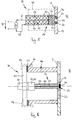
- FIG. 4 to 6 An apparatus 35 for measuring of a radio frequency discharge current at plasma reactor 2 is for example shown in Fig. 4 to 6 wherein the embodiment according to Fig. 6 is also schematically indicated in Fig. 3.
- the meter electrode 21 comprises an electrical insulation 37 on its peripheral surface 36.
- the insulation 37 is preferably formed like a ring.
- the meter electrode 21 is positioned in a flange or recess 40 of the reactor wall 5 acting as a part of the earth electrode 3 to 7 such that the insulation 37 is at least arranged between meter electrode 21 and wall 5 of reactor 2 and that the front face 41 of meter electrode 21 is aligned to the inner wall 43 of reactor 2 which inner wall is directed to the interior space 42 of the reactor.
- meter electrode 21 and insulation 37 form a part of the wall of the reactor.
- the front face 41 of meter electrode 21 is dimensioned in such a manner that the RF potential in reactor 2 effected by meter electrode 21 is negligible small with respect to the potential between plasma 17 and earth electrode 3 to 7.
- a first embodiment of apparatus 35 is shown in Fig. 4.
- Meter electrode 21 is mounted on wall 5 of reactor 2 by means of an electrically insulated vacuum feedthrough 44 which is indicated in Fig. 4 by broken lines.
- the meter electrode 21 comprises a rod-shaped electrical conductor 45 which is grounded outside from the reactor 2.
- the conductor 45 is connected to a current transformer 46 which generates a voltage U from the measured current I.
- the current transformer 46 is connected via a conductor 47 again to ground, i. e. to the wall 5 of the reactor. As described above, this voltage U is fed as an input quantity to the A/D converter 22 and from there as a digital signal to the data processing device 23 for further processing.
- the apparatus according to the first embodiment comprises a relatively high sensitivity because of the great surface of the electrodes which are used in this embodiment.
- the bandwidth of this apparatus is limited by the upper limiting frequency of the current transformer and by parasitic inductivities of the feed lines as well as by stray capacitances to about 150 MHz.
- FIG. 5 A further embodiment of apparatus 35 of the present invention is schematically and partly in cross-section shown in Fig. 5 wherein in the following identical or similar elements show the same reference numerals as in the first embodiment according to Fig. 4.
- a probe 20 is again provided which is mounted on wall 5 of reactor 2 by means of the vacuum feedthrough 44.
- the probe 20 comprises an inner conductor 51 connected to the meter electrode 21, an insulating body 52 circumferentially surrounding the inner conductor 51, the insulation 37 of the meter electrode 21 and an outer conductor 53 connected to wall 5 of reactor 2.
- the outer conductor 53 should preferably be provided within the flange or recess, but as close as possible to the inner side of the reactor wall 5.
- This probe 20 thus corresponds to a coaxial cable having a constant characteristic wave impedance of preferably 50 Ohm so that probe 20 has nearly the same construction as the above mentioned coaxial cable.
- the inner conductor 51 passes the current I measured by the meter electrode 21 to the real terminal resistor 50.
- This resistor is electrically connected via the conductor 47 to outer conductor 53 and wall 5 (ground) of the reactor.
- the current in the inner and outer conductor have the same amount. No external magnetic fields thus appear in connection with such a probe.
- the probe 20 is connected to a coaxial cable 54.
- This connection is however not shown in detail in Fig. 5 and may for example be a so called BNC connector, thus a bushing/connector arrangement (male/female connection).
- the vacuum feedthrough 44 only extends up to the outer end of the probe 20 and is sealed against the probe.
- the insulation 37 as well as the insulating body 52 are preferably made of Teflon (PTFE).
- the probe 20 shown in Fig. 5 and 6 is connected to the A/D converter 22 having a thermal resistor 50 of preferably 50 Ohm via the coaxial cable 54 comprising the inner conductor 51, the insulating body 52 and the outer conductor 53.
- the characteristic wave impedance of said coaxial cable corresponds to the characteristic wave impedance of probe 20 and terminal resistor 50.
- apparatus 35 according to the present invention is formed up to the actual meter electrode 21 as a coaxial cable (see Fig. 5), a wide bandwidth with respect to the frequency of the discharge current to be measured may be achieved by this probe.
- a transmission of the measured signal having a wide bandwidth may be performed free from reflections from the meter electrode to for example the entrance of the A/D converter 22.
- the terminal resistor 50 has for example 50 Ohm, which corresponds to the characteristic wave impedance of the cable
- the input resistance of the probe 20 is small if compared to the reactive impedance of the space charge capacity of the meter electrode 21 towards the plasma so that the RF potential in the reactor effected by the meter electrode is negligibly small if compared to the potential between the plasma and the earth electrode.
- the diameter of the meter electrode 21 is about 5 mm.
- FIG. 6 A further preferred embodiment of apparatus 35 according to the present invention is schematically shown partly in cross-section in Fig. 6.
- the vacuum feedthrough 44 shown therein is provided with a cover plate 55 which is securely connected to a flange-shaped shoulder 60 at the free end of the vacuum feedthrough 44 via a sealing ring 57 by means of clamps 56 which are not shown in detail.
- the cover plate 55 comprises at both sides a coaxial connector 61 wherein the one end is preferably formed like a connector (male) and the other end is preferably formed like a bushing (female).
- the coaxial connector 61 which is directed to the wall 5 of the reactor is connected to a corresponding counter connector 62 which is not shown in detail in Fig. 6.
- the elements of this connection (inner conductor 51, insulating body 52, outer conductor 53) correspond to those of the embodiment according to Fig. 5.
- the inner conductor 51 is electrically directly connected to the actual meter electrode 21 and the outer conductor 53 is electrically connected with the wall 5 of the reactor 2 via a wall element 63.
- the insulting body 52 and the insulation 37 extend on the one hand between the inner conductor 51 and the meter electrode 21 and on the other hand between the outer conductor 53 and the wall element 63.
- the insulating body 52 and the insulation 37 as well as the cover plate 55 are preferably made of Teflon. According to Fig. 6, the cylindrical portion of the vacuum feedthrough 44 is welded to the side wall 5 of the reactor.
- the discharge current flows from the meter electrode 21 via the inner conductor 51 and the conductor 24 shown in Fig. 3 to the A/D converter 22 and from said converter via a conductor 24 which is also formed as a coaxial cable, and the outer conductor 53 as well as the wall element 63 back to the side wall 5 of the reactor 2 which acts as a part of the earth electrode.
- the sealing ring 57 is formed like a vacuum sealing and that an unobjectionable electrical contact exists between the circumferential surface of the wall element 63 and the side wall 5 of the reactor.
- the excitation in the discharge current may be measured with a wide bandwidth up to about 500 MHz by the apparatus according to the last mentioned embodiment of the present invention. This measurement is relatively independent of the distance between probe 20 and A/D converter 22.
Landscapes
- Physics & Mathematics (AREA)
- Engineering & Computer Science (AREA)
- Plasma & Fusion (AREA)
- Spectroscopy & Molecular Physics (AREA)
- Health & Medical Sciences (AREA)
- Analytical Chemistry (AREA)
- Chemical & Material Sciences (AREA)
- Electromagnetism (AREA)
- General Health & Medical Sciences (AREA)
- Toxicology (AREA)
- Plasma Technology (AREA)
- Investigating, Analyzing Materials By Fluorescence Or Luminescence (AREA)
- Discharge Heating (AREA)
- Drying Of Semiconductors (AREA)
Claims (11)
- Verfahren zum Bestimmen absoluter Plasmaparameter unsymmetrischer Hochfrequenz (HF)-Niederdruckplasmen, umfassend die folgenden Schritte:a) Erzeugen eines hochfrequenten elektrischen Wechselfeldes mit Hilfe von Anregungsfequenzen zwischen etwa 10 und 100 MHz in einem Plasmareaktor, durch welches elektrische Wechselfeld sich die Entladung mittels infolge der Nichtlinearität der Raumladungsschicht vor der HF-Elektrode erzeugter Oberwellen im Entladungsstrom selbst zu Schwingungen anregt;b) Messen des in dem Plasmareaktor erzeugten hochfrequenten Entladungsstroms an einem als Masseelektrode wirkenden Teil des Plasmareaktors und Umwandeln des gemessenen Stroms in eine in Form analoger Signale vorliegende Spannung;c) Umwandeln der unter b) ermittelten analogen Signale in digitale Signale; undd) Berechnen der Plasmaparameter aus den unter c) erhaltenen digitalen Signalen mittels eines mathematischen Algorithmus.
- Verfahren nach Anspruch 1, dadurch gekennzeichnet, daß wenigstens eine Resonanzfrequenz der Entladung aus dem zeitlichen Verlauf des Entladungsstroms bestimmt wird.
- Verfahren nach Anspruch 1 oder 2, dadurch gekennzeichnet, daß aus dem zeitlichen Verlauf des Entladungsstroms die Ionendichteverteilung in der harmonischen Oszillation vor der HF-Elektrode bestimmt wird, wobei der gemessene Entladungsstrom durch eine näherungsweise frequenzunabhängige Teilung des gesamten Entladungsstroms gebildet wird.
- Verfahren nach Anspruch 3, dadurch gekennzeichnet, daß die frequenzunabhängige Teilung des gesamten Entladungsstroms in einer ersten Näherung über die Flächenverhältnisse von dem als Masseelektrode wirkenden Teil des Reaktors und der HF-Elektrode abgeschätzt wird.
- Verfahren nach einem der vorhergehenden Ansprüche, dadurch gekennzeichnet, daß aus dem zeitlichen Verlauf des Entladungsstroms die Dämpfungskonstante des durch Stöße der Elektronen mit Neutralteilchen des Plasmas gedämpft schwingenden Systems bestimmt wird.
- Verfahren nach einem der vorhergehenden Ansprüche, dadurch gekennzeichnet, daß zur Bestimmung des Absolutwertes der mittleren Schichtdicke der Raumladungsschicht vor der HF-Elektrode und/oder zur Bestimmung der mittleren Ionenenergie das an der HF-Elektrode anliegende Potential oder zumindest dessen Gleichanteil gemessen wird.
- Vorrichtung zum Messen des hochfrequenten Entladungsstroms an einem als Masseelektrode (3 bis 7) wirkenden Teil eines Plasmareaktors (2),
dadurch gekennzeichnet,daß eine Meßelektrode (21) auf ihrer Umfangsfläche (36) eine elektrische Isolierung aufweist und derart in einem Flansch oder einer Ausnehmung (40) der zumindest als Teil der Masseelektrode (3 bis 7) wirkenden Reaktorwand (5) angeordnet ist, daß sich die Isolierung (37) wenigstens zwischen Meßelektrode (21) und der Wand (5) des Reaktors (2) befindet und die Stirnfläche (41) der Meßelektrode (21) mit der zum Innenraum (42) des Reaktors (2) gerichteten Innenwand (43) des Reaktors (2) etwa fluchtet, unddaß die Stirnfläche (41) der Meßelektrode (21) so bemessen ist, daß das durch die Meßelektrode (21) bewirkte HF-Potential im Reaktor (2) vernachlässigbar klein gegenüber dem Potential zwischen Plasma (17) und Masseelektrode (3 bis 7) ist. - Vorrichtung nach Anspruch 7, dadurch gekennzeichnet, daß die Meßelektrode (21) mittels einer elektrisch isolierten Vakuumdurchführung (44) am Reaktor (2) befestigt ist und daß die Meßelektrode (21) einen stabförmigen, außerhalb des Reaktors (2) geerdeten elektrischen Leiter (45) aufweist, der mit einem aus dem gemessenen Strom (I) eine Spannung (U) erzeugenden Stromwandler (46) verbunden ist.
- Vorrichtung nach Anspruch 7, dadurch gekennzeichnet, daß ein mittels einer elektrisch isolierten Vakuumdurchführung (44) am Reaktor (2) befestigter Meßaufnehmer (20) vorgesehen ist, der einen mit der Meßelektrode (21) verbundenen Innenleiter (51), einen den Innenleiter (51) mantelförmig umgebenden Isolierkörper (52), die Isolierung (37) der Meßelektrode (21) und einen mit der Wand (5) des Reaktors (2) verbundenen Außenleiter (53) aufweist, wobei der Außenleiter (53) so nahe wie möglich an der Innenseite der Reaktorwand (5) mit dem Flansch oder der Ausnehmung versehen ist und wobei die Koaxialkonstruktion der Meßelektrode (21) derart ausgebildet ist, daß der Wellenwiderstand vorzugsweise 50 Ohm beträgt.
- Vorrichtung nach Anspruch 9, dadurch gekennzeichnet, daß der Meßaufnehmer (20) an einen Analog/Digital-Wandler (22) mit einem Abschlußwiderstand (50) von vorzugsweise 50 Ohm über ein den Innenleiter (51), den Isolierkörper (52) und den Außenleiter (53) aufweisendes Koaxialkabel (54) angeschlossen ist, dessen Wellenwiderstand demjenigen des Meßaufnehmers (20) und des Abschlußwiderstandes (50) entspricht.
- Vorrichtung nach Anspruch 9 oder 10, dadurch gekennzeichnet, daß die Vakuumdurchführung (44) beidseitig mit einem Koaxialanschluß (61) versehen ist, der mit einem entsprechenden, mit dem Innenleiter (51), dem Isolierkörper (52) und dem Außenleiter (53) verbundenen Gegenanschluß (62) verbindbar ist.
Applications Claiming Priority (2)
| Application Number | Priority Date | Filing Date | Title |
|---|---|---|---|
| DE4445762A DE4445762A1 (de) | 1994-12-21 | 1994-12-21 | Verfahren und Vorrichtung zum Bestimmen absoluter Plasmaparameter |
| DE4445762 | 1994-12-21 |
Publications (2)
| Publication Number | Publication Date |
|---|---|
| EP0719077A1 EP0719077A1 (de) | 1996-06-26 |
| EP0719077B1 true EP0719077B1 (de) | 1997-09-10 |
Family
ID=6536566
Family Applications (1)
| Application Number | Title | Priority Date | Filing Date |
|---|---|---|---|
| EP95119294A Expired - Lifetime EP0719077B1 (de) | 1994-12-21 | 1995-12-07 | Verfahren und Vorrichtung zur Bestimmung der absoluten Plasmaparameter |
Country Status (6)
| Country | Link |
|---|---|
| US (2) | US5705931A (de) |
| EP (1) | EP0719077B1 (de) |
| JP (1) | JP2872954B2 (de) |
| AT (1) | ATE158134T1 (de) |
| DE (2) | DE4445762A1 (de) |
| ES (1) | ES2109045T3 (de) |
Families Citing this family (54)
| Publication number | Priority date | Publication date | Assignee | Title |
|---|---|---|---|---|
| KR0179281B1 (ko) * | 1996-02-28 | 1999-10-01 | 문정환 | 챔버를 갖는 베이퍼-에치 장치의 에치-종말점 측정방법 |
| US6046594A (en) * | 1997-02-11 | 2000-04-04 | Advanced Energy Voorhees, Inc. | Method and apparatus for monitoring parameters of an RF powered load in the presence of harmonics |
| DE19722272A1 (de) * | 1997-05-28 | 1998-12-03 | Leybold Systems Gmbh | Vorrichtung zur Erzeugung von Plasma |
| JPH1183907A (ja) * | 1997-09-03 | 1999-03-26 | Mitsubishi Electric Corp | 高周波電流の測定方法 |
| US6043607A (en) * | 1997-12-16 | 2000-03-28 | Applied Materials, Inc. | Apparatus for exciting a plasma in a semiconductor wafer processing system using a complex RF waveform |
| GB9803932D0 (en) * | 1998-02-26 | 1998-04-22 | Matra Bae Dynamics Uk Ltd | Apparatus for the investigation of surface chemistry |
| US6151532A (en) * | 1998-03-03 | 2000-11-21 | Lam Research Corporation | Method and apparatus for predicting plasma-process surface profiles |
| JP3497092B2 (ja) * | 1998-07-23 | 2004-02-16 | 名古屋大学長 | プラズマ密度情報測定方法、および測定に用いられるプローブ、並びにプラズマ密度情報測定装置 |
| JP3497091B2 (ja) * | 1998-07-23 | 2004-02-16 | 名古屋大学長 | プラズマ生成用高周波パワーの制御方法、およびプラズマ発生装置 |
| WO2000055900A1 (en) * | 1999-03-17 | 2000-09-21 | Hitachi, Ltd. | Ion current density measuring method and instrument, and semiconductor device manufacturing method |
| DE19927063B4 (de) * | 1999-06-15 | 2005-03-10 | Christof Luecking | Verfahren zur Bestimmung der elektrischen Eigenschaften von hochfrequenzangeregten Gasentladungen durch Berechnung mit einer inversen Matrix, die durch einmalige Kalibrierung bestimmt wird |
| DE19961104A1 (de) * | 1999-12-17 | 2001-07-05 | Infineon Technologies Ag | Verfahren und Vorrichtung zur Überwachung von Ätzkammern |
| US6653852B1 (en) * | 2000-03-31 | 2003-11-25 | Lam Research Corporation | Wafer integrated plasma probe assembly array |
| US6841124B2 (en) * | 2000-10-02 | 2005-01-11 | Ethicon, Inc. | Sterilization system with a plasma generator controlled by a digital signal processor |
| US20040262146A1 (en) * | 2000-10-02 | 2004-12-30 | Platt Robert C. | Sterilization system plasma generation control |
| US6447719B1 (en) * | 2000-10-02 | 2002-09-10 | Johnson & Johnson | Power system for sterilization systems employing low frequency plasma |
| US6852277B2 (en) * | 2000-10-02 | 2005-02-08 | Ethicon, Inc. | Sterilization system employing a switching module adapted to pulsate the low frequency power applied to a plasma |
| WO2002054835A2 (en) * | 2001-01-08 | 2002-07-11 | Tokyo Electron Limited | Addition of power at selected harmonics of plasma processor drive frequency |
| WO2003036309A1 (en) * | 2001-10-24 | 2003-05-01 | Tokyo Electron Limited | Method and apparatus for electron density measurement |
| US6608446B1 (en) * | 2002-02-25 | 2003-08-19 | Eni Technology, Inc. | Method and apparatus for radio frequency (RF) metrology |
| US20030209518A1 (en) * | 2002-05-08 | 2003-11-13 | Taiwan Semiconductor Manufacturing Co., Ltd. | Method of detecting abnormal chamber conditions in etcher |
| US6894474B2 (en) * | 2002-06-07 | 2005-05-17 | Applied Materials, Inc. | Non-intrusive plasma probe |
| US6707255B2 (en) | 2002-07-10 | 2004-03-16 | Eni Technology, Inc. | Multirate processing for metrology of plasma RF source |
| US6812044B2 (en) * | 2002-12-19 | 2004-11-02 | Taiwan Semiconductor Manufacturing Co., Ltd | Advanced control for plasma process |
| AT502984B8 (de) * | 2003-09-15 | 2008-10-15 | Qasar Technologieentwicklung Gmbh | Verfahren und einrichtung zur erzeugung von alfven-wellen |
| US7288942B2 (en) * | 2003-10-02 | 2007-10-30 | Naoyuki Sato | Plasma potential measuring method and apparatus, and plasma potential measuring probe |
| US20060043063A1 (en) * | 2004-09-02 | 2006-03-02 | Mahoney Leonard J | Electrically floating diagnostic plasma probe with ion property sensors |
| EP1836716A4 (de) * | 2005-01-11 | 2009-12-23 | Innovation Engineering Llc | Verfahren zur erkennung einer an eine last gelieferten hf-leistung und der kompleximpedanz der last |
| US20060171848A1 (en) * | 2005-01-31 | 2006-08-03 | Advanced Energy Industries, Inc. | Diagnostic plasma sensors for endpoint and end-of-life detection |
| US7319316B2 (en) * | 2005-06-29 | 2008-01-15 | Lam Research Corporation | Apparatus for measuring a set of electrical characteristics in a plasma |
| US7479207B2 (en) * | 2006-03-15 | 2009-01-20 | Lam Research Corporation | Adjustable height PIF probe |
| JP4878187B2 (ja) * | 2006-03-20 | 2012-02-15 | 東京エレクトロン株式会社 | 基板処理装置、堆積物モニタ装置、及び堆積物モニタ方法 |
| DE102006014106B3 (de) | 2006-03-24 | 2007-08-30 | RUHR-UNIVERSITäT BOCHUM | Vorrichtung und Verfahren zur Messung der Dichte eines Plasmas |
| US7829468B2 (en) * | 2006-06-07 | 2010-11-09 | Lam Research Corporation | Method and apparatus to detect fault conditions of plasma processing reactor |
| EP2089894B1 (de) * | 2006-11-27 | 2011-06-01 | Dublin City University | Plasmasystem und messverfahren |
| EP2114112B1 (de) | 2008-04-29 | 2015-09-23 | Plasmetrex GmbH | Vorrichtung für industrielle Plasmaprozesse |
| GB2459858A (en) * | 2008-05-07 | 2009-11-11 | Univ Dublin City | System for analysing plasma |
| US7970562B2 (en) * | 2008-05-07 | 2011-06-28 | Advanced Energy Industries, Inc. | System, method, and apparatus for monitoring power |
| DE102009038563B4 (de) * | 2009-08-22 | 2013-06-06 | Reinhausen Plasma Gmbh | Vorrichtung und Verfahren zur Überwachung eines Plasmastrahls |
| US8190366B2 (en) * | 2010-10-01 | 2012-05-29 | The United States Of America, As Represented By The Secretary Of The Navy | LC resonance probe for determining local plasma density |
| DE102010055799B3 (de) * | 2010-10-06 | 2016-10-06 | RUHR-UNIVERSITäT BOCHUM | Vorrichtung und Verwendung der Vorrichtung zur Messung der Dichte und/oder der Elektronentemperatur und/oder der Stoßfrequenz eines Plasmas |
| RU2515539C1 (ru) * | 2012-12-14 | 2014-05-10 | Федеральное Государственное Бюджетное Образовательное Учреждение Высшего Профессионального Образования "Нижегородский Государственный Университет Им. Н.И. Лобачевского" | Способ модификации ионосферной плазмы |
| US11432732B2 (en) | 2016-06-28 | 2022-09-06 | Chiscan Holdings, Llc | System and method of measuring millimeter wave of cold atmospheric pressure plasma |
| US11166762B2 (en) * | 2016-06-28 | 2021-11-09 | Chiscan Holdings, L.L.C. | Non-thermal plasma generator for detection and treatment of maladies |
| CN106851953B (zh) * | 2017-02-22 | 2018-12-21 | 大连理工大学 | 一种凸凹探针及其等离子体诊断方法 |
| DE102018115389B3 (de) | 2018-06-26 | 2019-08-14 | RUHR-UNIVERSITäT BOCHUM | Sonde zur Messung von Plasmaparametern |
| JP2020136144A (ja) * | 2019-02-22 | 2020-08-31 | 株式会社アルバック | プラズマ状態測定装置、および、成膜装置 |
| CN114025664A (zh) | 2019-05-06 | 2022-02-08 | 智像控股有限责任公司 | 使用非热等离子体阵列的推定的能量场分析 |
| US11887812B2 (en) | 2019-07-12 | 2024-01-30 | Advanced Energy Industries, Inc. | Bias supply with a single controlled switch |
| US20210217588A1 (en) * | 2020-01-10 | 2021-07-15 | COMET Technologies USA, Inc. | Azimuthal sensor array for radio frequency plasma-based wafer processing systems |
| CN113648051B (zh) * | 2021-08-13 | 2022-08-02 | 卡本(深圳)医疗器械有限公司 | 一种基于emc-emi的自适应射频信号数据处理设备 |
| US12567572B2 (en) * | 2023-07-11 | 2026-03-03 | Advanced Energy Industries, Inc. | Plasma behaviors predicted by current measurements during asymmetric bias waveform application |
| US12255056B2 (en) | 2024-01-09 | 2025-03-18 | Southwest Jiaotong University | Diagnostic method and system for measuring potential and electric field of plasma |
| CN117545157B (zh) * | 2024-01-09 | 2024-03-12 | 西南交通大学 | 一种用于测量等离子体电势和电场的诊断方法及系统 |
Family Cites Families (11)
| Publication number | Priority date | Publication date | Assignee | Title |
|---|---|---|---|---|
| US4475063A (en) * | 1981-06-22 | 1984-10-02 | The United States Of America As Represented By The Administrator Of The National Aeronautics And Space Administration | Hollow cathode apparatus |
| US5053343A (en) * | 1985-02-15 | 1991-10-01 | Environmental Technologies Group, Inc. | Selective ionization of gas constituents using electrolytic reactions |
| GB2211244A (en) * | 1987-10-16 | 1989-06-28 | Ford Motor Co | I.c. engine combustion chamber ionisation sensor |
| US5274306A (en) * | 1990-08-31 | 1993-12-28 | Kaufman & Robinson, Inc. | Capacitively coupled radiofrequency plasma source |
| US5394092A (en) * | 1991-02-28 | 1995-02-28 | Valco Instruments Co., Inc. | System for identifying and quantifying selected constituents of gas samples using selective photoionization |
| EP0524022A1 (de) * | 1991-07-19 | 1993-01-20 | The Secretary Of State For Defence In Her Britannic Majesty's Government Of The United Kingdom Of Great Britain And Northern | Vorrichtung und Verfahren zum Nachweis von Gas |
| US5175472A (en) * | 1991-12-30 | 1992-12-29 | Comdel, Inc. | Power monitor of RF plasma |
| JP3292531B2 (ja) * | 1993-01-15 | 2002-06-17 | 忠弘 大見 | 高周波励起プラズマの計測装置 |
| JPH07169590A (ja) * | 1993-09-16 | 1995-07-04 | Fujitsu Ltd | 電子密度の測定方法及びその装置及び電子密度の制御装置及びプラズマ処理装置 |
| US5576629A (en) * | 1994-10-24 | 1996-11-19 | Fourth State Technology, Inc. | Plasma monitoring and control method and system |
| US5565737A (en) * | 1995-06-07 | 1996-10-15 | Eni - A Division Of Astec America, Inc. | Aliasing sampler for plasma probe detection |
-
1994
- 1994-12-21 DE DE4445762A patent/DE4445762A1/de not_active Withdrawn
-
1995
- 1995-09-15 US US08/529,020 patent/US5705931A/en not_active Expired - Lifetime
- 1995-11-28 JP JP7332746A patent/JP2872954B2/ja not_active Expired - Lifetime
- 1995-12-07 DE DE69500694T patent/DE69500694T2/de not_active Expired - Lifetime
- 1995-12-07 AT AT95119294T patent/ATE158134T1/de active IP Right Revival
- 1995-12-07 EP EP95119294A patent/EP0719077B1/de not_active Expired - Lifetime
- 1995-12-07 ES ES95119294T patent/ES2109045T3/es not_active Expired - Lifetime
-
1997
- 1997-04-15 US US08/842,564 patent/US5861752A/en not_active Expired - Lifetime
Also Published As
| Publication number | Publication date |
|---|---|
| EP0719077A1 (de) | 1996-06-26 |
| ES2109045T3 (es) | 1998-01-01 |
| US5861752A (en) | 1999-01-19 |
| US5705931A (en) | 1998-01-06 |
| JP2872954B2 (ja) | 1999-03-24 |
| ATE158134T1 (de) | 1997-09-15 |
| DE69500694D1 (de) | 1997-10-16 |
| DE69500694T2 (de) | 1998-03-26 |
| DE4445762A1 (de) | 1996-06-27 |
| JPH08222396A (ja) | 1996-08-30 |
Similar Documents
| Publication | Publication Date | Title |
|---|---|---|
| US5705931A (en) | Method for determining absolute plasma parameters | |
| Braithwaite et al. | An electrostatic probe technique for RF plasma | |
| JP5209313B2 (ja) | プラズマの励起電流の特性を測定するためのプローブ、および関連するプラズマ反応器 | |
| US6771481B2 (en) | Plasma processing apparatus for processing semiconductor wafer using plasma | |
| US4316791A (en) | Device for chemical dry etching of integrated circuits | |
| US5273610A (en) | Apparatus and method for determining power in plasma processing | |
| JP4270872B2 (ja) | インピーダンスをモニターするシステム並びに方法 | |
| Sobolewski | Electrical characteristics of argon radio frequency glow discharges in an asymmetric cell | |
| US5339039A (en) | Langmuir probe system for radio frequency excited plasma processing system | |
| Klick et al. | Plasma diagnostics in rf discharges using nonlinear and resonance effects | |
| JPH10509557A (ja) | プラズマ中のイオン流の測定方法及び装置 | |
| Schwabedissen et al. | Comparison of electron density measurements in planar inductively coupled plasmas by means of the plasma oscillation method and Langmuir probes | |
| JP2002063999A (ja) | プラズマ電位測定方法と測定用プローブ | |
| Sobolewski | Current and voltage measurements in the Gaseous Electronics Conference rf Reference Cell | |
| Annaratone et al. | On the use of double probes in RF discharges | |
| Klick et al. | Innovative plasma diagnostics and control of process in reactive low-temperature plasmas | |
| Hebner et al. | Electron and negative ion densities in C 2 F 6 and CHF 3 containing inductively coupled discharges | |
| US20190242838A1 (en) | Non-Invasive Method for Probing Plasma Impedance | |
| JPH06215893A (ja) | 高周波励起プラズマの計測装置 | |
| JP2023143758A (ja) | プラズマ処理チャンバ内を流れる無線周波数電流スペクトルの非侵襲検知のためのシステムおよび方法 | |
| Sherman et al. | Plasma Density and Electron Temperature Measurement in a Radio Frequency (RF) Cathode Using Double Langmuir Probes | |
| KR0159203B1 (ko) | 마이크로파 공진검침기 및 다이나믹 플라스마의 밀도 측정방법 | |
| Felts et al. | Practical Langmuir probe measurements in deposition plasmas | |
| Viel et al. | Modelling and characterization of a large-diameter plasma cylinder produced by surface waves | |
| Naz et al. | Testing of nickel-chrome alloy as a tip material for multi-tip langmuir probes |
Legal Events
| Date | Code | Title | Description |
|---|---|---|---|
| PUAI | Public reference made under article 153(3) epc to a published international application that has entered the european phase |
Free format text: ORIGINAL CODE: 0009012 |
|
| AK | Designated contracting states |
Kind code of ref document: A1 Designated state(s): AT BE CH DE ES FR GB IE IT LI NL SE |
|
| 17P | Request for examination filed |
Effective date: 19960807 |
|
| 17Q | First examination report despatched |
Effective date: 19961009 |
|
| GRAG | Despatch of communication of intention to grant |
Free format text: ORIGINAL CODE: EPIDOS AGRA |
|
| GRAH | Despatch of communication of intention to grant a patent |
Free format text: ORIGINAL CODE: EPIDOS IGRA |
|
| RAP3 | Party data changed (applicant data changed or rights of an application transferred) |
Owner name: ADOLF-SLABY-INSTITUT, FORSCHUNGSGESELLSCHAFT FUER |
|
| GRAH | Despatch of communication of intention to grant a patent |
Free format text: ORIGINAL CODE: EPIDOS IGRA |
|
| GRAA | (expected) grant |
Free format text: ORIGINAL CODE: 0009210 |
|
| AK | Designated contracting states |
Kind code of ref document: B1 Designated state(s): AT BE CH DE ES FR GB IE IT LI NL SE |
|
| REF | Corresponds to: |
Ref document number: 158134 Country of ref document: AT Date of ref document: 19970915 Kind code of ref document: T |
|
| REG | Reference to a national code |
Ref country code: CH Ref legal event code: EP |
|
| REF | Corresponds to: |
Ref document number: 69500694 Country of ref document: DE Date of ref document: 19971016 |
|
| ITF | It: translation for a ep patent filed | ||
| REG | Reference to a national code |
Ref country code: CH Ref legal event code: NV Representative=s name: E. BLUM & CO. PATENTANWAELTE |
|
| REG | Reference to a national code |
Ref country code: ES Ref legal event code: FG2A Ref document number: 2109045 Country of ref document: ES Kind code of ref document: T3 |
|
| ET | Fr: translation filed | ||
| REG | Reference to a national code |
Ref country code: IE Ref legal event code: FG4D Free format text: 76442 |
|
| PLBE | No opposition filed within time limit |
Free format text: ORIGINAL CODE: 0009261 |
|
| STAA | Information on the status of an ep patent application or granted ep patent |
Free format text: STATUS: NO OPPOSITION FILED WITHIN TIME LIMIT |
|
| 26N | No opposition filed | ||
| REG | Reference to a national code |
Ref country code: GB Ref legal event code: IF02 |
|
| REG | Reference to a national code |
Ref country code: CH Ref legal event code: PUE Owner name: ASI ADVANCED SEMICONDUCTOR INSTRUMENTS GMBH Free format text: ADOLF-SLABY-INSTITUT, FORSCHUNGSGESELLSCHAFT FUER PLASMATECHNOLOGIE, UND MIKROSTRUKTURIERUNG MBH#RUDOWER CHAUSSEE 6A#12489 BERLIN (DE) -TRANSFER TO- ASI ADVANCED SEMICONDUCTOR INSTRUMENTS GMBH#RUDOWER CHAUSSEE 30#12489 BERLIN (DE) |
|
| REG | Reference to a national code |
Ref country code: GB Ref legal event code: 732E |
|
| NLS | Nl: assignments of ep-patents |
Owner name: ASI ADVANCED SEMICONDUCTOR INSTRUMENTS GMBH |
|
| REG | Reference to a national code |
Ref country code: ES Ref legal event code: PC2A |
|
| REG | Reference to a national code |
Ref country code: FR Ref legal event code: TP |
|
| REG | Reference to a national code |
Ref country code: CH Ref legal event code: PFA Owner name: ASI ADVANCED SEMICONDUCTOR INSTRUMENTS GMBH Free format text: ASI ADVANCED SEMICONDUCTOR INSTRUMENTS GMBH#RUDOWER CHAUSSEE 30#12489 BERLIN (DE) -TRANSFER TO- ASI ADVANCED SEMICONDUCTOR INSTRUMENTS GMBH#RUDOWER CHAUSSEE 30#12489 BERLIN (DE) |
|
| PGFP | Annual fee paid to national office [announced via postgrant information from national office to epo] |
Ref country code: ES Payment date: 20091228 Year of fee payment: 15 Ref country code: CH Payment date: 20091228 Year of fee payment: 15 |
|
| PGFP | Annual fee paid to national office [announced via postgrant information from national office to epo] |
Ref country code: BE Payment date: 20100212 Year of fee payment: 15 |
|
| PGFP | Annual fee paid to national office [announced via postgrant information from national office to epo] |
Ref country code: AT Payment date: 20101119 Year of fee payment: 16 |
|
| PGFP | Annual fee paid to national office [announced via postgrant information from national office to epo] |
Ref country code: GB Payment date: 20101229 Year of fee payment: 16 |
|
| PGFP | Annual fee paid to national office [announced via postgrant information from national office to epo] |
Ref country code: SE Payment date: 20091230 Year of fee payment: 15 |
|
| BERE | Be: lapsed |
Owner name: *ASI ADVANCED SEMICONDUCTOR INSTRUMENTS G.M.B.H. Effective date: 20101231 |
|
| REG | Reference to a national code |
Ref country code: CH Ref legal event code: PL |
|
| REG | Reference to a national code |
Ref country code: SE Ref legal event code: EUG |
|
| PG25 | Lapsed in a contracting state [announced via postgrant information from national office to epo] |
Ref country code: BE Free format text: LAPSE BECAUSE OF NON-PAYMENT OF DUE FEES Effective date: 20101231 Ref country code: SE Free format text: LAPSE BECAUSE OF NON-PAYMENT OF DUE FEES Effective date: 20101208 |
|
| PG25 | Lapsed in a contracting state [announced via postgrant information from national office to epo] |
Ref country code: CH Free format text: LAPSE BECAUSE OF NON-PAYMENT OF DUE FEES Effective date: 20101231 Ref country code: LI Free format text: LAPSE BECAUSE OF NON-PAYMENT OF DUE FEES Effective date: 20101231 |
|
| REG | Reference to a national code |
Ref country code: ES Ref legal event code: FD2A Effective date: 20120206 |
|
| PG25 | Lapsed in a contracting state [announced via postgrant information from national office to epo] |
Ref country code: ES Free format text: LAPSE BECAUSE OF NON-PAYMENT OF DUE FEES Effective date: 20101208 |
|
| PGFP | Annual fee paid to national office [announced via postgrant information from national office to epo] |
Ref country code: FR Payment date: 20130110 Year of fee payment: 18 |
|
| PGFP | Annual fee paid to national office [announced via postgrant information from national office to epo] |
Ref country code: NL Payment date: 20121225 Year of fee payment: 18 |
|
| REG | Reference to a national code |
Ref country code: AT Ref legal event code: MM01 Ref document number: 158134 Country of ref document: AT Kind code of ref document: T Effective date: 20121207 |
|
| GBPC | Gb: european patent ceased through non-payment of renewal fee |
Effective date: 20121207 |
|
| PG25 | Lapsed in a contracting state [announced via postgrant information from national office to epo] |
Ref country code: AT Free format text: LAPSE BECAUSE OF NON-PAYMENT OF DUE FEES Effective date: 20121207 |
|
| PG25 | Lapsed in a contracting state [announced via postgrant information from national office to epo] |
Ref country code: GB Free format text: LAPSE BECAUSE OF NON-PAYMENT OF DUE FEES Effective date: 20121207 |
|
| PGFP | Annual fee paid to national office [announced via postgrant information from national office to epo] |
Ref country code: IE Payment date: 20131226 Year of fee payment: 19 |
|
| PGFP | Annual fee paid to national office [announced via postgrant information from national office to epo] |
Ref country code: IT Payment date: 20131224 Year of fee payment: 19 |
|
| REG | Reference to a national code |
Ref country code: NL Ref legal event code: V1 Effective date: 20140701 |
|
| REG | Reference to a national code |
Ref country code: FR Ref legal event code: ST Effective date: 20140829 |
|
| PG25 | Lapsed in a contracting state [announced via postgrant information from national office to epo] |
Ref country code: NL Free format text: LAPSE BECAUSE OF NON-PAYMENT OF DUE FEES Effective date: 20140701 |
|
| PG25 | Lapsed in a contracting state [announced via postgrant information from national office to epo] |
Ref country code: FR Free format text: LAPSE BECAUSE OF NON-PAYMENT OF DUE FEES Effective date: 20131231 |
|
| PGFP | Annual fee paid to national office [announced via postgrant information from national office to epo] |
Ref country code: DE Payment date: 20150226 Year of fee payment: 20 |
|
| REG | Reference to a national code |
Ref country code: IE Ref legal event code: MM4A |
|
| PG25 | Lapsed in a contracting state [announced via postgrant information from national office to epo] |
Ref country code: IE Free format text: LAPSE BECAUSE OF NON-PAYMENT OF DUE FEES Effective date: 20141207 |
|
| REG | Reference to a national code |
Ref country code: DE Ref legal event code: R071 Ref document number: 69500694 Country of ref document: DE |
|
| PG25 | Lapsed in a contracting state [announced via postgrant information from national office to epo] |
Ref country code: IT Free format text: LAPSE BECAUSE OF NON-PAYMENT OF DUE FEES Effective date: 20141207 |