EP0718045B1 - Handbetätigte Pumpe mit Vordruckkammer zum Zerstäuben einer Flüssigkeit und Abgabevorrichtung mit einer solchen Pumpe - Google Patents
Handbetätigte Pumpe mit Vordruckkammer zum Zerstäuben einer Flüssigkeit und Abgabevorrichtung mit einer solchen Pumpe Download PDFInfo
- Publication number
- EP0718045B1 EP0718045B1 EP95402419A EP95402419A EP0718045B1 EP 0718045 B1 EP0718045 B1 EP 0718045B1 EP 95402419 A EP95402419 A EP 95402419A EP 95402419 A EP95402419 A EP 95402419A EP 0718045 B1 EP0718045 B1 EP 0718045B1
- Authority
- EP
- European Patent Office
- Prior art keywords
- precompression
- chamber
- pump
- piston
- liquid
- Prior art date
- Legal status (The legal status is an assumption and is not a legal conclusion. Google has not performed a legal analysis and makes no representation as to the accuracy of the status listed.)
- Expired - Lifetime
Links
Images

Classifications
-
- B—PERFORMING OPERATIONS; TRANSPORTING
- B05—SPRAYING OR ATOMISING IN GENERAL; APPLYING FLUENT MATERIALS TO SURFACES, IN GENERAL
- B05B—SPRAYING APPARATUS; ATOMISING APPARATUS; NOZZLES
- B05B11/00—Single-unit hand-held apparatus in which flow of contents is produced by the muscular force of the operator at the moment of use
- B05B11/0005—Components or details
- B05B11/0037—Containers
- B05B11/0039—Containers associated with means for compensating the pressure difference between the ambient pressure and the pressure inside the container, e.g. pressure relief means
- B05B11/0044—Containers associated with means for compensating the pressure difference between the ambient pressure and the pressure inside the container, e.g. pressure relief means compensating underpressure by ingress of atmospheric air into the container, i.e. with venting means
-
- B—PERFORMING OPERATIONS; TRANSPORTING
- B05—SPRAYING OR ATOMISING IN GENERAL; APPLYING FLUENT MATERIALS TO SURFACES, IN GENERAL
- B05B—SPRAYING APPARATUS; ATOMISING APPARATUS; NOZZLES
- B05B11/00—Single-unit hand-held apparatus in which flow of contents is produced by the muscular force of the operator at the moment of use
- B05B11/01—Single-unit hand-held apparatus in which flow of contents is produced by the muscular force of the operator at the moment of use characterised by the means producing the flow
- B05B11/10—Pump arrangements for transferring the contents from the container to a pump chamber by a sucking effect and forcing the contents out through the dispensing nozzle
- B05B11/1001—Piston pumps
- B05B11/1015—Piston pumps actuated without substantial movement of the nozzle in the direction of the pressure stroke
-
- B—PERFORMING OPERATIONS; TRANSPORTING
- B05—SPRAYING OR ATOMISING IN GENERAL; APPLYING FLUENT MATERIALS TO SURFACES, IN GENERAL
- B05B—SPRAYING APPARATUS; ATOMISING APPARATUS; NOZZLES
- B05B11/00—Single-unit hand-held apparatus in which flow of contents is produced by the muscular force of the operator at the moment of use
- B05B11/01—Single-unit hand-held apparatus in which flow of contents is produced by the muscular force of the operator at the moment of use characterised by the means producing the flow
- B05B11/10—Pump arrangements for transferring the contents from the container to a pump chamber by a sucking effect and forcing the contents out through the dispensing nozzle
- B05B11/1042—Components or details
- B05B11/1061—Pump priming means
-
- B—PERFORMING OPERATIONS; TRANSPORTING
- B05—SPRAYING OR ATOMISING IN GENERAL; APPLYING FLUENT MATERIALS TO SURFACES, IN GENERAL
- B05B—SPRAYING APPARATUS; ATOMISING APPARATUS; NOZZLES
- B05B11/00—Single-unit hand-held apparatus in which flow of contents is produced by the muscular force of the operator at the moment of use
- B05B11/0005—Components or details
- B05B11/0062—Outlet valves actuated by the pressure of the fluid to be sprayed
Definitions
- the invention relates to a precompression pump for spraying under pressure a liquid, and in particular a cosmetic product such as a hair spray.
- the invention aims, in particular, to provide a pump of this kind, manually operable and compact, so that it can be housed in the cover of a liquid dispenser cover.
- Document EP-A 0 437 131 discloses, in the name of the applicant, a manual precompression pump, comprising, inter alia, a liquid pumping chamber in communication with a precompression chamber, a spray nozzle connected by a distribution channel to the precompression chamber, and a supply channel provided with a non-return valve opening into the pumping chamber.
- the precompression pump of the kind described in EP-A 0 437 131 deserves to be improved from the point of view of spraying precision, since the actuation of this pump is carried out by pressing a button. pusher which at the same time includes the spray nozzle. As a result, the location where the spray is to be applied is difficult to target.
- this known pump is difficult to assemble.
- all the constituent parts of this pump are aligned on the same axis of symmetry, its bulk in the axial direction is relatively large, which prohibits its use in many embodiments employing a covering hood.
- the present invention aims to remedy the drawbacks of the prior art, by providing the user with a dispensing assembly for a liquid of simple construction, the dispensing head of which is fixed and which includes a precompression pump, small footprint and a reduced number of parts, and therefore, from an industrial point of view, is easy to assemble.
- the pressure drop has been minimized compared to the pump according to EP-A 0 437 131, so that the spray quality is improved. This results in a reduction in the particle size of the liquid leaving the nozzle.
- the present invention relates to a precompression pump as defined in claim 1.
- This pump is intended to be mounted on a tank containing the liquid to be dispensed.
- the first piston is also called the actuating piston, and the second piston, the compression piston.
- a means can be provided causing the evacuation of the air inside the pump body, disposed between the first and the second pistons.
- this means is a central pot formed at the top of the second piston, facing the pumping chamber; this stud is able to come into abutment against the first piston, when the operating member is actuated, that is to say, when the volume of the pumping chamber is at a minimum.
- a mechanical connection is established between the two pistons, the first pushing the second in a position such that the compressed air in the pump body can escape goes to the precompression chamber and the distribution channel.
- the nozzle is fixed relative to the pump body.
- This spray nozzle is provided with an oriented spray orifice, along an axis substantially orthogonal to the axis of symmetry which defines the precompression chamber.
- the sliding means for placing in communication and for closing this pump consists, according to a first embodiment, by a pin, preferably frustoconical, formed at the top of the second piston. In the pump's rest position, the pin therefore closes the communication between the precompression chamber and the pumping chamber.
- the pump is actuated, by pushing the operating member against the first elastic return means, the pressure of the liquid which is inside the pump body will rise to a predetermined value and cause this communication, by pushing the precompression member against the second elastic return means. It is clear that the predetermined value of precompression depends on the force developed by this second elastic return means.
- a means for bringing the reservoir to atmospheric pressure can be provided, constituted, for example, by an air intake orifice pierced in the external wall of the pump body, opening into the lower part of the precompression chamber, that is to say in the part where the second elastic return means is arranged, in order to balance the pressure prevailing in the tank with the external pressure.
- a sealing means can be arranged between the air intake orifice and the reservoir, closing this orifice during storage period and capable of admitting a dose of air into the reservoir during the distribution of a respective dose of liquid.
- a first sealing lip of annular shape is carried by the second piston, located in an area between the distribution channel and the air intake orifice.
- this sealing means between the air intake orifice and the reservoir is a second annular lip carried by the precompression piston which is arranged inside the precompression chamber. This second lip is placed at a level located between the first lip and the reservoir.
- the precompression chamber is provided with a flared zone, situated at the lower end of this precompression chamber, on the side of the reservoir, between the second sealing lip, when it is in the rest position, and a bottom, which separates the precompression chamber from the tank.
- an orifice is provided between the precompression chamber and the tank.
- this orifice is a capillary orifice, made in the form of cylindrical tubing crossed by a capillary channel.
- the capillary channel has the function of preventing the liquid from the reservoir from entering the lower part of the precompression chamber, on the side of the second return means. This arrangement is all the more useful if the liquid to be dispensed is a composition capable of drying or clogging the precompression piston, such as, for example, a hair spray or a paint.
- the second sealing lip of the precompression piston is no longer in contact with the inner wall of the precompression chamber, and air coming from the intake orifice air can penetrate, via the capillary channel, into the precompression chamber and the reservoir, in order to replace with air, an equivalent volume of a dose of liquid dispensed.
- the sliding means for connecting and closing the pump can be constituted by an annular sealing ring, integral with the second piston and facing the first piston, and pressing against an edge or a peripheral groove of the passage between the precompression chamber and the pumping chamber, capable of closing this passage.
- the first elastic return means housed in the pumping chamber, consists of a helical spring, preferably made of metal.
- the second elastic return means preferably also consists of a metal helical spring.
- the non-return valve which prevents the liquid accumulated in the pumping chamber from going back down into the tank, preferably comprises a spherical ball housed in a frustoconical portion of the supply channel. Via a dip tube this channel communicates with the liquid contained in a reservoir.
- This pump can be used for spraying numerous liquids, such as, for example, a cosmetic composition, in particular a hair spray, a body deodorant, a dermatological lotion, or a pharmaceutical composition.
- a cosmetic composition in particular a hair spray, a body deodorant, a dermatological lotion, or a pharmaceutical composition.
- the invention also relates to a liquid distribution assembly, in the form of droplets, comprising the reservoir for the liquid to be distributed, surmounted by a precompression pump conforming to the characteristics which have just been described.
- a means of fixing the pump to the reservoir containing the liquid to be sprayed can be provided.
- This fixing means comprises, for example, a disc-shaped element, extending radially to the pump body and comprising a peripheral part shaped as a cylindrical skirt, provided inside a snap-fitting bead, able to cooperate with an additional annular groove, produced on a neck with which the reservoir is provided.
- the reservoir may, in addition, comprise a covering hood, fixed to the reservoir, this hood surrounding the pump mounted on this reservoir.
- the pump operating member is actuated by means of a lever arm, articulated on a wall of the covering hood.
- This arrangement allows the user to spray the liquid in good conditions, precisely, while making, upon actuation, a lower effort than that required for the pump of the prior art.
- the pump 501 comprises a body 503, generally cylindrical, intended to be fixed to the neck 525 of the reservoir.
- the fixing is carried out by a snap ring 516, consisting of a cylindrical skirt 516a, carrying inside an annular rib 516b, able to cooperate with the bead 526 of the neck.
- the skirt 516a is connected to the periphery of a disc-shaped element 516d, itself extending radially from the pump body 503.
- This disc-shaped element 516d comprises, on the side facing the reservoir, an annular rib 516c, bearing against an annular rim 541 of a bowl 540, folded radially outwards.
- the rim 541 is sandwiched between the snap ring 516 and the neck 525 of the reservoir.
- the pump body 503 forms, at its end remote from the reservoir, a cylindrical pumping chamber 502 having a central axis X of revolution, chamber in which is housed a helical compression spring 509, generally metallic, which is pressed against a first piston 507.
- This piston 507 is connected to an actuator 506, cylindrical, having an emerging end 506a used for actuating the pump.
- this first piston 507 On the side facing the reservoir, this first piston 507 has an extension 506b which is inserted inside the turns of the spring 509.
- the piston 507 further comprises two annular sealing lips applying against the internal wall of the body 503, lips of which a first 507a is turned on the side of the emerging end 506a, while the second 507b is turned in the opposite direction.
- a fixing cup 508 comprising a bead snap 508c inside, this bead cooperating with an annular bulge 503a which is provided with the free end 503b of the body 503.
- the cup 508 has, on its side facing the tank, a cylindrical skirt 508a, used for sliding guidance of the operating member 506.
- the pump body 503 is connected in its central region to a cylindrical extension 517 of revolution around an axis Z substantially perpendicular to the central axis X, this extension constituting a distribution element.
- the distribution element 517 has an annular recess 517a, which leads to a distribution channel 518 parallel to the axis Z, this channel leading to a precompression chamber 505 having an axis of revolution Y.
- the axis Y is parallel to the X axis and orthogonal to the Z axis.
- the annular recess 517a defines a central stud 519, on the end of which is fixed a spray nozzle 520, provided with a central orifice 521. It is of course possible to vary the angle formed between the axes X and Z, by choosing an angle which can range, for example from about 45 ° to about 135 °, depending on the intended use.
- the pumping chamber 502 On the side facing the reservoir, the pumping chamber 502 is extended by a cylindrical bore, of reduced diameter compared to the diameter of the pumping chamber 502, forming the precompression chamber 505 delimited by a cylindrical wall 505b.
- the precompression chamber has a Y axis parallel to the X axis, the X and Y axes being offset.
- the transition zone between the pumping chamber and the precompression chamber has an annular restriction defining a passage 550, at the level of the nozzle 520.
- the supply channel 518 communicates with the precompression chamber 505.
- the wall 505b of the precompression chamber is provided with an air return orifice 505a, the role of which will be explained below, during the description of the operation of the pump.
- the precompression chamber 505 comprises a precompression piston 510, of generally elongated cylindrical shape, capable of sliding in leaktight manner in this chamber, and which is provided with two sealing lips 510a, 510e.
- the lip 510e is situated at a level lower than that of the lip 510a, relative to the reservoir 524. Furthermore, the two lips have a free edge which is directed on the same side, towards the pumping chamber 502.
- the lip 510a prevents any communication between the air intake orifice 505a and the distribution channel 518.
- the passage 550 between the pumping chamber 502 and the precompression chamber is formed by an internal radial projection, against the edge of which abuts , in the pump rest position, a frustoconical pin 551 of the precompression piston, constituting a sliding means of communication and closing F, suitable for close the passage 550, in the rest position, and to establish communication, in the liquid distribution position, between the pumping chamber 502 and the precompression chamber 505.
- the lip 510e constitutes a temporary sealing means between the exterior and the tank.
- the precompression member 510 on the side facing the pumping chamber 502, carries a central stud 510d crossing the passage 550 and extending into the pumping chamber 502. Its role will be explained below.
- the lower part 510c of the precompression piston 510 turned towards the reservoir, is supported on the turns of a second helical spring 511, constituting a second elastic return means, which has the function of pushing, in the rest position, the precompression piston 510 in the closed position of passage 550.
- This spring 511 abuts against an internal annular projection 510g carried by the precompression piston.
- the bowl 540 is engaged in the neck 525 of the reservoir and has a generally cylindrical shape. It comprises a cylindrical peripheral wall 543, carrying at its upper part, the abovementioned annular flange 541.
- the bowl 540 is closed, on the side opposite the rim, by a bottom 542. This bottom comprises, on the side facing the pumping chamber, a chimney 544 crossed by a capillary channel 523a, having the same axis of symmetry Y as the piston precompression.
- the spring 511 surrounds the chimney 544 and bears on the bottom 542.
- This bottom 542 is, moreover, traversed by a tube 504, fitting into a complementary tube 504b which, itself is connected to the pumping chamber 502 by a liquid supply passage 504c.
- the tubing 504 On the side facing the reservoir, the tubing 504 has a conical restriction zone, in which is disposed a ball 515 having a diameter intermediate between that of the supply channel and that of the restriction zone 504a, acting as a valve. liquid intake and preventing the liquid sucked into the pump body from going back down into the tank 524.
- the restriction zone 504a is extended by a dip tube 513 plunging permanently into the liquid to be dispensed contained in the tank 524.
- the tubing 504 has an axis of symmetry W.
- the W axis is parallel to the X and Y axes, and orthogonal to the Z axis. It is interesting to note that the W, X, Y and Z axes lie in the same plane (that of Figure 6).
- the operation of the precompression pump 501 according to the invention is as follows: at rest, the pump is in the position shown in the figure, the body 503 containing air, and the liquid being in the reservoir 524 .
- the user must first prime the pump, that is to say fill the body 503 with liquid, this operation expelling air. For this, it must press once or twice on the operating member 506. During this operation, the air enclosed in the body 503 is compressed. In the low position, the surface 506b of the operating member 506 bears against the stud 510d of the second piston 510, from which it results in a descent of the latter, thus freeing the passage 550 through which the compressed air can escape, via distribution channel 518 and nozzle 520.
- the spring 509 causes the piston 507 to rise. Consequently, a vacuum is created in the body 503, which also causes the non-return valve 504a to open. , 515, that is to say a displacement of the ball 515, and the ascent of a certain quantity of liquid in the body 503. From the moment when the body 503 is filled with liquid, the depression of the piston 507 causes a rapid rise in pressure in the body 503. Next, the precompression member 510 moves, the frustoconical pin 551 thus freeing the passage 550, through which the liquid is conveyed to the spray orifice 521, where produced, thanks to the short distance to be traveled in the distribution channel 518, a spraying of the good quality liquid.
- a vacuum is installed in the reservoir 524.
- the orifice 505a opening to the outside can be put in place. communication with the reservoir 524 via the precompression chamber and the capillary channel 523a.
- the rest position which corresponds to the high position of the precompression piston 510, no communication is possible, that is to say that the precompression chamber 505 does not communicate with the distribution channel 518, due to the presence of the lip 510a, and the air intake orifice 505a does not communicate with the reservoir 524, because the lip 510e makes a seal.
- the lip 510e slides in a zone 523b, where the precompression chamber has a larger section, and where the rupture of the sealing between the lip 510e and the interior wall 505b of the chamber 505, and the air coming from the orifice 505a can penetrate into the reservoir 524, thus putting it at atmospheric pressure.
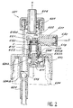
- FIG. 2 there is shown a second embodiment of a precompression pump according to the invention.
- the constituent parts bear the reference numbers of parts which are analogous or play a role similar to those of FIG. 6, increased by 100.
- the description of the provisions identical to those of FIG. 6 will only be repeated partially.
- the precompression member comprises a piston 610, the end of which faces towards the pumping chamber 602, carries an annular sealing ring 660 cooperating with a complementary annular groove 661 formed around a passage 650; this crown 660 closes, in the pump rest position, the passage 650 between the pumping chamber 602 and the precompression chamber 605.
- the piston 610 is mounted on a spring 611 which ensures, in the rest position, the elastic closure of the communication and closing means F.
- the positioning of the spring 611 is ensured by a bowl 640 of identical construction as that of the pump shown in FIG. 1.
Landscapes
- Containers And Packaging Bodies Having A Special Means To Remove Contents (AREA)
- Reciprocating Pumps (AREA)
- Closures For Containers (AREA)
Claims (18)
- Vordruckpumpe (501, 601) zur Zerstäubung einer Flüssigkeit unter konstantem Druck, mit:- einem zylindrischen Gehäuse (503, 603), das eine zylindrische Pumpkammer (502, 602) festlegt, die eine Rotationsachse (X) aufweist und in der ein erster Kolben (507, 607) sitzt, der einem Betätigungsorgan (506, 606) zugeordnet ist, wobei dieser Kolben gegen erste elastische Rückstellmittel (509, 609) anliegt;- einer zylindrischen Vordruckkammer (505, 605), die eine Rotationsachse (Y) aufweist und mit einem zweiten Kolben (510, 610) versehen ist, der gegen zweite elastische Rückstellmittel (511, 611) anliegt, wobei die Vordruckkammer imstande ist, mit der Pumpkammer (502, 602) durch einen Kanal (550, 650) in Verbindung zu treten;- einem Einspeisungskanal (504, 604), der mit einem Rückschlagventil (515, 504a; 615, 604a) versehen ist und in die Pumpkammer (502, 602) einmündet;- einem Verteilerelement (517, 617), das mit einer Zerstäuberdüse (520, 620) und einem Verteilungskanal (518, 618) versehen ist, der die Düse mit der Vordruckkammer verbindet, wobei diese Vordruckkammer gleitende Mittel (F) zum Herstellen der Verbindung und zum Absperren des genannten Kanals (550, 650) derart aufweist, daß die Verbindung in der Ruhelage der Pumpe unterbrochen ist, und daß die Verbindung bei der Vorverdichtung unter Wirkung des Betätigungsorgans hergestellt ist, wobei die gleitenden Mittel (F) zum Herstellen der Verbindung und zum Absperren dann den Kanal (550, 650) zwischen der Vordruckkammer und der Pumpkammer (502, 602) freigeben, dadurch gekennzeichnet, daß die Achse (Y) der Vordruckkammer (505, 605) in Bezug auf die Achse (X) der Pumpkammer (502, 602) versetzt ist, daß die Vordruckkammer (505, 605) in der Verlängerung der Pumpkammer (502, 602) gelegen ist, daß die Düse (520, 620) auf der Höhe einer Übergangszone zwischen der Vordruckkammer (505, 605) und der Pumpkammer (502, 602) gelegen ist, und daß die Flüssigkeit, die in der Pumpkammer (502, 602) enthalten ist, unmittelbar der Vordruckkammer (505, 605) während der Herstellung ihrer Verbindung unter der Betätigung des Betätigungsorgans (506, 606) zugeht.
- Vordruckpumpe nach Anspruch 1, dadurch gekennzeichnet, daß die Düse (520, 620) in Bezug auf das Gehäuse (503, 603) der Pumpe festgelegt ist.
- Vordruckpumpe nach Anspruch 1 oder 2, dadurch gekennzeichnet, daß die Zerstäuberdüse (520, 620) mit einer Zerstäubungsöffnung (521, 621) versehen ist, die längs einer Achse (Z) ausgerichtet ist, die im wesentlichen senkrecht zur Achse (X) angeordnet ist.
- Vordruckpumpe nach einem der Ansprüche 1 bis 3, dadurch gekennzeichnet, daß die gleitenden Mittel (F) zum Herstellen der Verbindung und zum Absperren von einem ringförmigen Dichtungskranz (660) gebildet sind, der fest mit dem zweiten Kolben (610) verbunden ist und gegen einen Rand oder eine Umfangsnut (651) des Kanals (650) anliegt und imstande ist, diesen zu versperren.
- Vordruckpumpe nach einem der Ansprüche 1 bis 3, dadurch gekennzeichnet, daß die gleitenden Mittel (F) zum Herstellen der Verbindung und zum Absperren von einem Zahn (551) gebildet sind, der auf dem Scheitel des zweiten Kolbens (510) dem ersten Kolben (507) gegenüberliegend ausgebildet ist und imstande ist, den genannten Kanal (550) zu versperren.
- Vordruckpumpe nach einem der Ansprüche 1 bis 5, dadurch gekennzeichnet, daß die Achse der Pumpkammer (X), der Vordruckkammer (Y) und der Zerstäubungsöffnung (Z) in ein und derselben Ebene gelegen sind.
- Vordruckpumpe nach einem der Ansprüche 1 bis 6, dadurch gekennzeichnet, daß die ersten elastischen Rückstellmittel (509, 609) von einer wendelförmigen Feder gebildet sind.
- Vordruckpumpe nach einem der Ansprüche 1 bis 7, dadurch gekennzeichnet, daß die zweiten elastischen Rückstellmittel (511, 611) von einer wendelförmigen Feder gebildet sind.
- Vordruckpumpe nach einem der Ansprüche 1 bis 8, dadurch gekennzeichnet, daß das Rückschlagventil eine Kugel (515, 615) aufweist, die in einem kegelstumpfförmigen Abschnitt (504a, 604a) des Einspeisungskanals (504, 604) sitzt.
- Vordruckpumpe nach einem der Ansprüche 1 bis 9, dadurch gekennzeichnet, daß die Vordruckkammer (505, 605) einen Kapillarkanal (523a, 623a) aufweist, der diese Vordruckkammer und einen Vorratsbehälter (524, 624) in Verbindung bringt, der die auszugebende Flüssigkeit enthält.
- Vordruckpumpe nach einem der Ansprüche 1 bis 10, dadurch gekennzeichnet, daß die Vordruckkammer (505, 605) mit Mitteln (505a, 523a; 605a, 623a) zum Verbringen auf den Atmosphären- bzw. Umgebungsdruck versehen ist.
- Vordruckpumpe nach Anspruch 11, dadurch gekennzeichnet, daß die Mittel (505a, 523a; 605a, 623a) zur Verbringung auf den Umgebungsdruck eine Luftausgleichsöffnung (505a, 605a), eine Verbindung (523a, 623a) zwischen der Vordruckkammer (505, 605) und dem Vorratsbehälter (524, 624) sowie Dichtungsmittel (510e, 610e) aufweisen, die fest mit dem zweiten Kolben (510, 610) verbunden sind, wobei diese Dichtungsmittel in der Ruhelage der Pumpe wirksam und in der Betätigungslage unwirksam sind.
- Vordruckpumpe nach Anspruch 12, dadurch gekennzeichnet, daß die Dichtungsmittel (510e, 610e) eine ringförmige Lippe sind, die in der Ruhelage der Pumpe in dichter Berührung mit der zylindrischen Wand der Vordruckkammer steht und einen Luftausgleichskanal (523b, 623b) während der Betätigung der Pumpe freigibt.
- Vordruckpumpe nach einem der Ansprüche 1 bis 13, dadurch gekennzeichnet, daß Mittel zum Erleichtern des Betriebsbeginns der Pumpe während der ersten Benutzung zwischen dem ersten Kolben (507, 607) und dem zweiten Kolben (510, 610) angeordnet sind.
- Vordruckpumpe nach einem der Ansprüche 1 bis 14, dadurch gekennzeichnet, daß die den Betriebsbeginn der Pumpe erleichternden Mittel ein mittiges Stück (510d, 610d) sind, das an der Oberseite des zweiten Kolbens (510, 610) gelegen ist, wobei dieses Stück in Anlage gegen den ersten Kolben (507, 607) gelangt, wenn sich dieser in einer Lage befindet, in welcher das Volumen der Pumpkammer (502, 602) ein Minimum beträgt.
- Abgabevorrichtung für eine Flüssigkeit in Form von Tröpfchen, mit einem Vorratsbehälter (524, 624) für die abzugebende Flüssigkeit, über dem eine Vordruckpumpe (501, 601) nach irgendeinem der Ansprüche 1 bis 15 angebracht ist.
- Vorrichtung nach Anspruch 16, dadurch gekennzeichnet, daß Befestigungsmittel (516, 616) der Pumpe auf dem Vorratsbehälter (524, 624) vorgesehen sind, der die zu zerstäubende Flüssigkeit enthält.
- Vorrichtung nach einem der Ansprüche 16 oder 17, dadurch gekennzeichnet, daß das Betätigungsorgan (506, 606) mittels eines Hebelarmes betätigt wird.
Applications Claiming Priority (2)
| Application Number | Priority Date | Filing Date | Title |
|---|---|---|---|
| FR9414036A FR2727162B1 (fr) | 1994-11-23 | 1994-11-23 | Pompe manuelle a precompression pour la pulverisation d'un liquide et ensemble de distribution equipe d'une telle pompe |
| FR9414036 | 1994-11-23 |
Publications (2)
| Publication Number | Publication Date |
|---|---|
| EP0718045A1 EP0718045A1 (de) | 1996-06-26 |
| EP0718045B1 true EP0718045B1 (de) | 1997-07-16 |
Family
ID=9469072
Family Applications (1)
| Application Number | Title | Priority Date | Filing Date |
|---|---|---|---|
| EP95402419A Expired - Lifetime EP0718045B1 (de) | 1994-11-23 | 1995-10-30 | Handbetätigte Pumpe mit Vordruckkammer zum Zerstäuben einer Flüssigkeit und Abgabevorrichtung mit einer solchen Pumpe |
Country Status (9)
| Country | Link |
|---|---|
| US (1) | US5709325A (de) |
| EP (1) | EP0718045B1 (de) |
| JP (1) | JP2809605B2 (de) |
| AR (1) | AR000260A1 (de) |
| BR (1) | BR9504967A (de) |
| CA (1) | CA2163483C (de) |
| DE (1) | DE69500443T2 (de) |
| ES (1) | ES2105854T3 (de) |
| FR (1) | FR2727162B1 (de) |
Families Citing this family (18)
| Publication number | Priority date | Publication date | Assignee | Title |
|---|---|---|---|---|
| US5887763A (en) * | 1997-09-09 | 1999-03-30 | Continental Sprayers International, Inc. | Reciprocating fluid pump with bottle closure having inner and outer rim seals |
| FR2779129B1 (fr) * | 1998-05-26 | 2000-08-18 | Sofab | Diffuseur de produits liquides sous forme d'aerosols |
| JP2005524494A (ja) * | 2002-05-09 | 2005-08-18 | グラクソ グループ リミテッド | 流体分配装置 |
| GB0305583D0 (en) * | 2003-03-11 | 2003-04-16 | Glaxo Group Ltd | A fluid dispensing device |
| DE102004050679A1 (de) * | 2004-10-13 | 2006-04-20 | Ing. Erich Pfeiffer Gmbh | Dosiervorrichtung |
| EP1974825B1 (de) * | 2006-01-26 | 2013-05-08 | Mitani Valve Co., Ltd. | Inhaltsabgabemechanismus für pumpenartigen behälter und pumpenartiges produkt mit inhaltsabgabemechanismus |
| US20070228074A1 (en) * | 2006-04-03 | 2007-10-04 | Mueller Edward L | Spray bottle neck finish |
| WO2010078310A1 (en) * | 2008-12-30 | 2010-07-08 | Idispense, Llc | Dispenser cap retainer for child resistant concentrate cartridge |
| DE102009006430A1 (de) * | 2009-01-23 | 2010-07-29 | Ing. Erich Pfeiffer Gmbh | Austragvorrichtung |
| IT1401659B1 (it) * | 2010-09-16 | 2013-08-02 | Guala Dispensing Spa | Dispositivo di erogazione per liquidi |
| DE102011081980B4 (de) | 2011-09-01 | 2023-07-06 | Gebr. Schmid Gmbh & Co. | Vorrichtung zum Benetzen von flachen Substraten und Anlage mit einer solchen Vorrichtung |
| ITBS20130159A1 (it) * | 2013-11-05 | 2015-05-06 | Guala Dispensing Spa | Dispositivo di erogazione a grilletto |
| ITUB20159355A1 (it) * | 2015-12-23 | 2017-06-23 | Taplast Srl | Dispositivo per l?erogazione di fluidi o miscele |
| ITUB20159576A1 (it) * | 2015-12-23 | 2017-06-23 | Taplast Srl | Dispositivo per l?erogazione di fluidi o miscele |
| DE102016212893A1 (de) * | 2016-07-14 | 2018-01-18 | F. Holzer Gmbh | Pumpkopf sowie Dosiervorrichtung |
| CN109794373B (zh) * | 2019-03-11 | 2023-09-12 | 东莞市川玮机械有限公司 | 一种智能喷雾系统及其工作流程 |
| CN110329654B (zh) * | 2019-08-08 | 2024-04-16 | 浙江晟祺实业有限公司 | 一种新型喷头改进结构 |
| EP3821987B1 (de) * | 2019-11-15 | 2022-09-28 | Aptar Radolfzell GmbH | Flüssigkeitsspender mit flaschenbelüftung |
Family Cites Families (10)
| Publication number | Priority date | Publication date | Assignee | Title |
|---|---|---|---|---|
| US3337096A (en) * | 1966-03-21 | 1967-08-22 | White Lab Inc | Pump-type dispenser |
| US3489322A (en) * | 1968-02-21 | 1970-01-13 | Acu Tech Corp | Dispenser pump |
| FR2634825B1 (fr) * | 1988-07-26 | 1994-03-04 | Debard Andre | Pompe a precompression pour la diffusion d'un liquide |
| FR2656900B1 (fr) | 1990-01-10 | 1994-01-28 | Oreal | Pompe manuelle a precompression pour la pulverisation d'un liquide, notamment d'un parfum. |
| AU595786B3 (en) * | 1990-01-10 | 1990-03-12 | Chung Ming Pan | Spray head assembly |
| US5192006A (en) * | 1991-05-01 | 1993-03-09 | Risdon Corporation | Low profile pump |
| US5181635A (en) * | 1991-05-31 | 1993-01-26 | Calmar Inc. | Liquid pump dispenser having a stationary spout |
| US5125545A (en) * | 1991-07-01 | 1992-06-30 | Makk-O Industries, Inc. | Pumping valve |
| FR2699835B1 (fr) * | 1992-12-28 | 1995-03-31 | Oreal | Ensemble pour la pulvérisation d'un liquide comportant une pompe à précompression. |
| US5425476A (en) * | 1994-06-29 | 1995-06-20 | Monturas S.A. | Pump sprayer with stationary discharge |
-
1994
- 1994-11-23 FR FR9414036A patent/FR2727162B1/fr not_active Expired - Fee Related
-
1995
- 1995-10-30 EP EP95402419A patent/EP0718045B1/de not_active Expired - Lifetime
- 1995-10-30 ES ES95402419T patent/ES2105854T3/es not_active Expired - Lifetime
- 1995-10-30 DE DE69500443T patent/DE69500443T2/de not_active Expired - Fee Related
- 1995-11-17 BR BR9504967A patent/BR9504967A/pt not_active IP Right Cessation
- 1995-11-21 JP JP7303084A patent/JP2809605B2/ja not_active Expired - Lifetime
- 1995-11-22 CA CA002163483A patent/CA2163483C/fr not_active Expired - Fee Related
- 1995-11-22 AR AR33433195A patent/AR000260A1/es unknown
- 1995-11-24 US US08/562,626 patent/US5709325A/en not_active Expired - Fee Related
Also Published As
| Publication number | Publication date |
|---|---|
| US5709325A (en) | 1998-01-20 |
| CA2163483C (fr) | 1998-12-01 |
| BR9504967A (pt) | 1997-10-21 |
| EP0718045A1 (de) | 1996-06-26 |
| CA2163483A1 (fr) | 1996-05-24 |
| DE69500443T2 (de) | 1997-11-06 |
| DE69500443D1 (de) | 1997-08-21 |
| ES2105854T3 (es) | 1997-10-16 |
| FR2727162B1 (fr) | 1996-12-20 |
| JPH08224508A (ja) | 1996-09-03 |
| FR2727162A1 (fr) | 1996-05-24 |
| AR000260A1 (es) | 1997-06-18 |
| JP2809605B2 (ja) | 1998-10-15 |
Similar Documents
| Publication | Publication Date | Title |
|---|---|---|
| EP0718045B1 (de) | Handbetätigte Pumpe mit Vordruckkammer zum Zerstäuben einer Flüssigkeit und Abgabevorrichtung mit einer solchen Pumpe | |
| EP0688609B1 (de) | Vordruck-Handpumpe zur Zerstäuben einer Flüssigkeit und Abgabevorrichtung mit einer solchen Pumpe | |
| EP0623060B1 (de) | Vordruckpumpe | |
| EP0757592B1 (de) | Pumpe mit vordruckaufbau | |
| EP0709305B1 (de) | Abgabeventil und mit diesem versehener Spender | |
| EP0734969B1 (de) | Aerosolbehälter, versehen mit zwei Sprühdüsen | |
| WO1994015716A1 (fr) | Dispositif portatif pour projeter des doses d'une substance fluide a l'aide d'un flux d'air comprime | |
| EP1205255B1 (de) | Pumpe zur Abgabe eines Produktes, insbesondere eines kosmetischen Mittels oder eines Pflegemittels | |
| LU85400A1 (fr) | Pompe de distribution a commande manuelle | |
| EP0747131B1 (de) | Pumpenvorrichtung zum Entnehmen einer Flüssigkeit aus einem Behälter und zu deren Zerstäubung | |
| EP0544549B1 (de) | Pumpe zur Förderung von einem flüssigen oder pastösen Produkt, und Ausgabebehälter mit einer solchen Pumpe | |
| EP0669167B1 (de) | Anordnung zur quasi-kontinuierlichen Abgabe von Flüssigkeiten mit einer Pumpe und Gebrauch einer solchen Anordnung zum Zerstäuben von Haarlack | |
| EP0658490B1 (de) | Herabdrückbares Ventil zum Zerstäuben einer Flüssigkeit und mit diesem Ventil versehener Druckbehälter | |
| EP0605275B1 (de) | Anordnung zur Zerstäubung einer Flüssigkeit mit einer Vordruckpumpe | |
| EP0897323B1 (de) | Ausgabevorrichtung mit feststehender sprühdüse | |
| EP0086144B1 (de) | Vorrichtung zum Zerstäuben von präzisen Dosen von Aerosol | |
| FR2814727A1 (fr) | Valve destinee a equiper un dispositif pour la distribution sous pression d'un produit, et dispositif ainsi equipe | |
| EP1616632B1 (de) | Pumpe zum Ausbringen eines Produkts in verschiedenen Sprühpositionen und entsprechender Behälter | |
| FR2698083A1 (fr) | Pot de distribution à pompe et coupelle d'actionnement. | |
| EP0561666B1 (de) | Flüssigkeitspender mit einer Abgabepumpe und Abgabepumpe für einen solchen Spender | |
| EP0499537B1 (de) | Vorrichtung zur Zerstäubung oder Abgabe eines flüssigen Produktes mit einem Schiebesteigrohr im Saugrohr | |
| FR2724125A1 (fr) | Distributeur pour un produit liquide muni d'un piston et piston destine a equiper un tel distributeur | |
| WO1992001183A1 (fr) | Clapet pour pulverisateur | |
| FR2814726A1 (fr) | Valve destinee a equiper un dispositif pour la distribution sous pression d'un produit, et dispositif ainsi equipe |
Legal Events
| Date | Code | Title | Description |
|---|---|---|---|
| PUAI | Public reference made under article 153(3) epc to a published international application that has entered the european phase |
Free format text: ORIGINAL CODE: 0009012 |
|
| AK | Designated contracting states |
Kind code of ref document: A1 Designated state(s): DE ES FR GB IT |
|
| 17P | Request for examination filed |
Effective date: 19960722 |
|
| GRAG | Despatch of communication of intention to grant |
Free format text: ORIGINAL CODE: EPIDOS AGRA |
|
| 17Q | First examination report despatched |
Effective date: 19961007 |
|
| GRAH | Despatch of communication of intention to grant a patent |
Free format text: ORIGINAL CODE: EPIDOS IGRA |
|
| GRAH | Despatch of communication of intention to grant a patent |
Free format text: ORIGINAL CODE: EPIDOS IGRA |
|
| GRAA | (expected) grant |
Free format text: ORIGINAL CODE: 0009210 |
|
| AK | Designated contracting states |
Kind code of ref document: B1 Designated state(s): DE ES FR GB IT |
|
| GBT | Gb: translation of ep patent filed (gb section 77(6)(a)/1977) |
Effective date: 19970729 |
|
| REF | Corresponds to: |
Ref document number: 69500443 Country of ref document: DE Date of ref document: 19970821 |
|
| REG | Reference to a national code |
Ref country code: ES Ref legal event code: FG2A Ref document number: 2105854 Country of ref document: ES Kind code of ref document: T3 |
|
| PLBE | No opposition filed within time limit |
Free format text: ORIGINAL CODE: 0009261 |
|
| STAA | Information on the status of an ep patent application or granted ep patent |
Free format text: STATUS: NO OPPOSITION FILED WITHIN TIME LIMIT |
|
| 26N | No opposition filed | ||
| PGFP | Annual fee paid to national office [announced via postgrant information from national office to epo] |
Ref country code: FR Payment date: 20011010 Year of fee payment: 7 |
|
| PGFP | Annual fee paid to national office [announced via postgrant information from national office to epo] |
Ref country code: ES Payment date: 20011025 Year of fee payment: 7 |
|
| PGFP | Annual fee paid to national office [announced via postgrant information from national office to epo] |
Ref country code: GB Payment date: 20011031 Year of fee payment: 7 |
|
| PGFP | Annual fee paid to national office [announced via postgrant information from national office to epo] |
Ref country code: DE Payment date: 20011112 Year of fee payment: 7 |
|
| REG | Reference to a national code |
Ref country code: GB Ref legal event code: IF02 |
|
| PG25 | Lapsed in a contracting state [announced via postgrant information from national office to epo] |
Ref country code: GB Free format text: LAPSE BECAUSE OF NON-PAYMENT OF DUE FEES Effective date: 20021030 |
|
| PG25 | Lapsed in a contracting state [announced via postgrant information from national office to epo] |
Ref country code: ES Free format text: LAPSE BECAUSE OF NON-PAYMENT OF DUE FEES Effective date: 20021031 |
|
| PG25 | Lapsed in a contracting state [announced via postgrant information from national office to epo] |
Ref country code: DE Free format text: LAPSE BECAUSE OF NON-PAYMENT OF DUE FEES Effective date: 20030501 |
|
| GBPC | Gb: european patent ceased through non-payment of renewal fee | ||
| PG25 | Lapsed in a contracting state [announced via postgrant information from national office to epo] |
Ref country code: FR Free format text: LAPSE BECAUSE OF NON-PAYMENT OF DUE FEES Effective date: 20030630 |
|
| REG | Reference to a national code |
Ref country code: FR Ref legal event code: ST |
|
| REG | Reference to a national code |
Ref country code: ES Ref legal event code: FD2A Effective date: 20031112 |
|
| PG25 | Lapsed in a contracting state [announced via postgrant information from national office to epo] |
Ref country code: IT Free format text: LAPSE BECAUSE OF NON-PAYMENT OF DUE FEES Effective date: 20051030 |