EP0544549B1 - Pumpe zur Förderung von einem flüssigen oder pastösen Produkt, und Ausgabebehälter mit einer solchen Pumpe - Google Patents
Pumpe zur Förderung von einem flüssigen oder pastösen Produkt, und Ausgabebehälter mit einer solchen Pumpe Download PDFInfo
- Publication number
- EP0544549B1 EP0544549B1 EP92402897A EP92402897A EP0544549B1 EP 0544549 B1 EP0544549 B1 EP 0544549B1 EP 92402897 A EP92402897 A EP 92402897A EP 92402897 A EP92402897 A EP 92402897A EP 0544549 B1 EP0544549 B1 EP 0544549B1
- Authority
- EP
- European Patent Office
- Prior art keywords
- product
- air
- pump
- piston
- stem
- Prior art date
- Legal status (The legal status is an assumption and is not a legal conclusion. Google has not performed a legal analysis and makes no representation as to the accuracy of the status listed.)
- Expired - Lifetime
Links
Images


Classifications
-
- B—PERFORMING OPERATIONS; TRANSPORTING
- B05—SPRAYING OR ATOMISING IN GENERAL; APPLYING FLUENT MATERIALS TO SURFACES, IN GENERAL
- B05B—SPRAYING APPARATUS; ATOMISING APPARATUS; NOZZLES
- B05B11/00—Single-unit hand-held apparatus in which flow of contents is produced by the muscular force of the operator at the moment of use
- B05B11/01—Single-unit hand-held apparatus in which flow of contents is produced by the muscular force of the operator at the moment of use characterised by the means producing the flow
- B05B11/10—Pump arrangements for transferring the contents from the container to a pump chamber by a sucking effect and forcing the contents out through the dispensing nozzle
- B05B11/1001—Piston pumps
- B05B11/1023—Piston pumps having an outlet valve opened by deformation or displacement of the piston relative to its actuating stem
- B05B11/1025—Piston pumps having an outlet valve opened by deformation or displacement of the piston relative to its actuating stem a spring urging the outlet valve in its closed position
-
- B—PERFORMING OPERATIONS; TRANSPORTING
- B05—SPRAYING OR ATOMISING IN GENERAL; APPLYING FLUENT MATERIALS TO SURFACES, IN GENERAL
- B05B—SPRAYING APPARATUS; ATOMISING APPARATUS; NOZZLES
- B05B11/00—Single-unit hand-held apparatus in which flow of contents is produced by the muscular force of the operator at the moment of use
- B05B11/01—Single-unit hand-held apparatus in which flow of contents is produced by the muscular force of the operator at the moment of use characterised by the means producing the flow
- B05B11/10—Pump arrangements for transferring the contents from the container to a pump chamber by a sucking effect and forcing the contents out through the dispensing nozzle
- B05B11/1087—Combination of liquid and air pumps
-
- B—PERFORMING OPERATIONS; TRANSPORTING
- B05—SPRAYING OR ATOMISING IN GENERAL; APPLYING FLUENT MATERIALS TO SURFACES, IN GENERAL
- B05B—SPRAYING APPARATUS; ATOMISING APPARATUS; NOZZLES
- B05B15/00—Details of spraying plant or spraying apparatus not otherwise provided for; Accessories
- B05B15/50—Arrangements for cleaning; Arrangements for preventing deposits, drying-out or blockage; Arrangements for detecting improper discharge caused by the presence of foreign matter
Definitions
- the invention relates to a pump for dispensing a product, liquid or pasty, through a dispensing nozzle, a pump of the type which includes: a pump body intended to be mounted on a container containing the product to be distribute; a push-button mounted sliding relative to the pump body and suitable for being pressed, against elastic return means, to cause the distribution of the product; a precompression valve provided to allow this distribution of the product only when sufficient pressure is reached; and air compression means provided for expelling air through the nozzle after dispensing the product in order to purge the outlet duct.
- Such a so-called self-purging pump aims to reduce the clogging problems which arise due to the drying of the product remaining in the pump distribution channel. This drawback is particularly important in the case of lacquer or cream pumps. In the case of a cream is added to the problem of plugging by drying, the problem of contamination of the remaining product.
- FR-A-2 434 943 shows, in particular in FIG. 3, a pump of this type.
- a liquid is precompressed in a chamber until a precompression valve opens allowing dispensing by spraying.
- Pressing the push button also makes it possible to compress the air under this push button and, at the end of pressing the push button, a passage is opened to the compressed air which can expel the remaining liquid through the nozzle. Release.
- a pump according to this document is relatively complicated and, when it is at rest, the passage intended to open for compressed air can become blocked. Indeed, this passage is occupied by the liquid when the pump is at rest and there may be drying of this liquid leading to an obstruction of said passage. In addition, the amplitude of the push button stroke during which the compressed air ensures the liquid purge is relatively low.
- the object of the invention is, above all, to provide a self-draining pump of the kind defined above which is of a simple construction, which makes it possible to carry out an effective purging of all the pipes through which the liquid passes, which facilitates the arrival of the purge air in these pipes and which reduces the opportunities for contact between the liquid contained in the pump body and the purge air. It is further desirable that such a pump has a great smoothness of operation and allows to easily start the distribution.
- a pump for the distribution of a liquid or pasty product, through a distribution nozzle of the kind defined above is characterized in that the air compression means are arranged to expel the air, through the nozzle, during the ascent phase of the push button under the action of the elastic return means, and that during the descent phase of the push button the above compression means carry out an air suction in order to its subsequent expulsion, while a dose of product is distributed through the nozzle.
- the air compression means advantageously comprise means for admitting air into a compartment of the pump body and means allowing this air to be evacuated through the normal pipes of the pump when the push-button is raised. .
- the air intake means are arranged to ensure the entry of air into the compartment at the end of depressing the push button.
- the precompression valve is advantageously arranged to cut the communication between the air compression means and the product outlet channel when said valve allows the product to be dispensed through said outlet channel.
- the pump body comprises a cylindrical part in which can move in longitudinal sliding a rod, linked to the push button, which has a channel longitudinal opening, in the upper part, into a pipe leading to the nozzle and communicating, at its lower part, by at least one radial passage with the lateral surface of the rod, the precompression valve comprising a piston mounted to slide around the rod, at the radial passage, between two stops, this piston sealingly separates the pump body into two compartments, namely an air compartment located above the piston and a product compartment located below the piston, the piston being able to take a high position for which the product compartment communicates with the aforesaid radial passage, while the air compartment is separated therefrom, and a low position for which the product compartment is separated from the radial passage while the air compartment is connected at this radial passage.
- the precompression valve comprising a piston mounted to slide around the rod, at the radial passage, between two stops, this piston sealingly separates the pump body into two compartments, namely an air compartment located
- the product compartment is fitted with a suction valve and has a nozzle in the lower part to which a dip tube is connected.
- the rod of the push-button advantageously comprises a collar located above the piston and a precompression spring is disposed between this collar and the piston, this spring tending to push the piston against the lower stop to keep it in the low position.
- this precompression spring can be relatively stiff while when the product to be dispensed is a paste, this spring has a very low stiffness.
- the elastic return means of the push button comprise a spring disposed between the lower end of the rod and the bottom of the pump body equipped with the product suction valve and the dip tube.
- the rod of the push-button slides, in the upper part, in a leaktight manner in a cap closing the pump body, and this rod comprises, upwards, an air intake means allowing air to enter the compartment. air pressure while pushing the button.
- the air intake means may include a longitudinal groove formed on the upper part of the rod.
- the air intake means comprises an upper part, of the rod, of smaller diameter sliding in a kind of sleeve extending upwards a cap closing the pump body.
- the pump may comprise, between the air compartment cover and the fixing capsule on the container, an air intake channel allowing air to enter the container as the product is evacuated.
- the lower part of the product compartment has a constricted zone capable of stopping the piston at the end of the push-button pushing stroke in order to move it to the high position and facilitate priming of the pump by evacuation of the air. parasite in the product compartment at the start of pumping.
- the invention also relates to a product dispenser container, liquid or pasty, equipped with a pump as defined above.
- Figure 1 of these drawings is a vertical axial section of a self-draining pump, according to the invention, and of the upper part of a container equipped with such a pump, shown in the rest position.
- Figure 2 shows, similarly to Figure 1, the pump while the push button is being pressed.
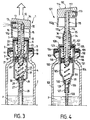
- Figure 3 shows, similarly to Figure 1, the pump during the ascent of the push button.
- Figure 4 is an axial vertical section of an alternative embodiment of the pump, shown in the rest position.
- Figure 5 shows the pump of Figure 4 while the push button is being pressed.
- Figure 6 finally, shows, in vertical axial section, the pump of Figure 4 at the end of depressing the push button, at the time of priming.
- the pump 1 comprises a pump body 4 fixed to the neck 3 by means of a crimping ring 5.
- the pump body 4 is constituted by a cylindrical part, open at its upper end and provided, on its upper periphery, with a rib 6 snap-fastening in a groove of a cap 7 covering the upper part of the body 4.
- a sealing washer 8, forming an internal seal, is clamped between the upper end of the body 4 and the cap 7
- This cap is provided with a collar 9 projecting radially outwards.
- a sealing washer 10 is disposed between the upper face of the neck 3 and the flange 9, so as to be clamped between these elements during the crimping of the ring 5.
- the upper face of the neck 3 advantageously comprises a circular sealing rib 11, in particular with a triangular cross section which is anchored in the washer 10.
- the pump 1 also comprises a push button 12 fitted with a dispensing nozzle 13 provided on the side wall of this button, the upper surface 14 of which serves as a bearing surface for the user.
- the button 12 is integral with a rod 15 slidingly mounted coaxially with the pump body 4 and passing in leaktight manner through the central orifice of the washer 8, at least when the push-button 12 is in the high rest position illustrated on the figure 1.
- the rod 15 comprises an axial longitudinal channel 16 opening, in the upper part, into a transverse conduit 17 of the push-button 12 communicating with the outlet orifice of the nozzle 13.
- the channel 16 stops before the the lower end of the rod 15 and communicates radially, for example by two diametrically opposite passages 18, with the lateral surface of the rod 15.
- the passages 18 are provided substantially at mid-length of a cylindrical seat f of reduced diameter of the rod 15, this seat f being axially limited upwards by a shoulder 19 forming a stop and downwards by another shoulder 20, also forming stop.
- a piston 21 is mounted around this bearing surface f of reduced diameter so as to be able to slide between a high position where the piston 21 is in abutment against the stop 19 and a low position where the piston 21 is in abutment against the shoulder 20.
- the rod 15 comprises, above the piston 21, a flange 22 serving to support a precompression spring 23 which tends to apply the piston 21 against the lower shoulder 20.
- the piston 21 divides the pump body 4 into two superimposed compartments, separated in a sealed manner by this piston 21.
- the upper compartment 24 will be called the air compartment, while the lower compartment 25 will be called the product compartment.
- the lower part 26 of the compartment 25 and therefore of the pump body 4 has a frustoconical shape and ends in an axial nozzle 27 to which is connected a dip tube 28 extending to the bottom of the container 2.
- a ball suction valve 29 is provided at the end of the lower part 26.
- the ball 29 is located inside a cylindrical cage 30 allowing the movement of the ball for opening the valve, but ensuring maintaining this ball in the vicinity of the seat provided on the internal surface of the part 26.
- a return spring 31 is provided between the lower end of the rod 15, arranged in the form of a pin around which the upper end of the spring 31 is engaged, and the frustoconical part 26. The lower end of the spring 31 is engaged around the cylindrical cage 30.
- the piston 21, combined with the passages 18 and the spring 23, constitutes a precompression valve.
- the rod 15 is provided, on its outer surface, in the upper part, with a longitudinal groove 32 intended to allow entry of air, in compartment 24, when this groove, through its lower part, crosses the washer 8 as illustrated in FIG. 2.
- the button 12 has a lower skirt 12 a which covers the cap 7, as illustrated in FIG. 2, at the end of depressing the push button 12.
- the assembly of the rod 15 and of the push-button 12 is in the high rest position, under the action of the spring 31.
- a dose of product P is located in the compartment 25.
- the user To dispense the dose, the user, as illustrated in FIG. 2, exerts manual pressure on the push-button 12 so as to push it in and bring the rod 15 down into the pump body 4.
- the valve 29 remains in the closed position and the piston 21, descending with the rod 15, compresses the dose of product contained in the compartment 25.
- the air compartment 24 is closed at the top and the rise of the piston 21 compresses the air from the container 24 and expels it through the passages 18 , the pipe 16, the passage 17 and the nozzle 13, thereby purging all these conduits of the remains of the product P which may remain after the previous distribution phase.
- the purge or sweep operation which takes place during the ascent phase is particularly effective and is spread over part of this ascent phase.
- FIGS. 1 to 3 corresponds to a pump without air return in the container 2. If a pump with air return was to be used, an air return channel of the kind of that shown on Figures 4 to 6 would be provided between the washer 8 and the cap 7 to allow the entry of air into the container 2 as and when the product P.
- the pump body 104 has a narrowing 33 at its base provided in such a way that before the end of the sinking of the rod 115, the piston 121 abuts against this narrowing 33. Thus, the piston 121 is stopped while the rod 115 can continue to descend. The piston 121 therefore moves upwards relative to the rod 115 by compressing the spring 123 and causing communication the radial passages 118 with the compartment 125. The piston 121, which comes into abutment against the upper shoulder 119 cuts the communication between the air compartment 124 and the passages 118 and 116.
- the rod 115 instead of having an air inlet groove similar to the groove 32 in the figures 1 to 3, has an upper part 115 a of smaller outside diameter than that of the lower part 115 b .
- the part 115 b slides in leaktight manner in the central opening of the washer 108; on the other hand, when the part 115 a arrives at the height of the washer 108, as illustrated in FIG. 6, an air inlet in the compartment 124 is created.
- the cap 107 is extended, upwards, by a tubular sleeve 34 coaxial with the pump body 104 whose internal diameter is slightly greater than the external diameter of the part 115 b .
- This sleeve 34 ends, in the upper part, with a throttled part 35 against which the substantially frustoconical shoulder 36 comes into watertight support 36 between the parts 115 a and 115 b of the rod 115 in the high rest position of the push button 112.
- the constricted part 35 has a cylindrical end whose internal diameter is slightly greater than the external diameter of the part 115 a so that an air passage is possible between the part 115 a and the internal surface of the part 35 when the rod 115 is pressed in and the shoulder 36 is no longer pressing against the throttled part 35.
- An air passage 37 constituted for example by a groove formed in the internal face of the cap 107 is provided for communicating the internal volume of the sleeve 34 with the internal volume of the container 102, bypassing the upper edge of the pump body 104
- the passage 37 constitutes an air intake channel for the container 102. This channel 37 is eliminated in the case where it is desired that the pump 101 operates without air intake.
- the operation of the pump 101 is as follows.
- the user by pressing the push button 112, lowers the rod 115 in the pump body.
- the rod drives the piston 121 which remains in the low position, pressing against the shoulder 120, due to the action of the precompression spring 123.
- the air trapped in compartment 125 is compressed.
- the piston 121 is stopped against the throttle 33.
- the rod 115 can continue to descend so that the piston 121 passes into the high position in abutment against the shoulder 119 which opens the passage 118 and allows the evacuation of the compressed air from the compartment 125 towards the atmosphere.
- the rod 115 When the part 115 has a smaller diameter, the rod 115 reaches and exceeds, when descending, the washer 108, air can enter the air compartment 124.
- the pump according to the invention can be used both for spraying a liquid and for dispensing a cream.
- the precompression spring 23, 123 will be chosen with a high stiffness in order to guarantee a good quality of spraying.
- the precompression spring 123 will be practically nonexistent and will have a very low stiffness.
- the self-draining pump according to the invention ensures an expulsion of air in the same pipes and the same outlet nozzle as the product.
- the residual product is thus expelled from the pump which avoids clogging, drying, contamination and other similar disadvantages.
Claims (11)
- Pumpe (1;101) zur Abgabe eines flüssigen oder pastösen Produktes (P) über eine Abgabedüse (13;113), welche einen auf einem das abzugebende Produkt enthaltenden Behälter (2;102) befestigbaren Pumpenkörper (4;104) und einen Druckknopf (12;112) umfaßt, der gegen den Widerstand von elastischen Rückstellmitteln (31;131) eingedrückt werden kann, um die Abgabe des Produktes zu bewirken, wobei die Pumpe ein Vorverdichtungsventil (18,21,23;118,121,123) aufweist, das die Produktabgabe nur dann ermöglicht, wenn ein ausreichender Druck erreicht ist, wobei außerdem Luftverdichtungsmittel (21,24;121,124) vorgesehen sind, um nach der Abgabe des Produktes die Luft durch die Düse hinauszutreiben, dadurch gekennzeichnet, daß die Luftverdichtungsmittel (21,24;121,124) angeordnet sind, um die Luft während der Anstiegsphase des Druckknopfes (12,112) unter der Wirkung der elastischen Rückstellmittel (31,131) durch die Düse (13,113) hinauszutreiben, und daß während der Abstiegsphase des Druckknopfes (12,112) die Luftverdichtungsmittel (24,21) ein Ansaugen von Luft für ihren späteren Ausstoß bewirken, während eine bestimmte Menge des Produktes (P) über die Düse (13,113) abgegeben wird.
- Pumpe gemäß Anspruch 1, dadurch gekennzeichnet, daß das Vorverdichtungsventil (18,21,23;118,121,123) für ein Unterbrechen der Verbindung zwischen den Luftverdichtungsmitteln (21,24;121,124) und dem Austrittskanal (16,116) für das Produkt eingerichtet ist, wenn das Ventil die Abgabe des Produktes (P) durch den Austrittskanal (16,116) ermöglicht.
- Pumpe gemäß Anspruch 1 oder 2, dadurch gekennzeichnet, daß der Pumpenkörper (4,104) einen zylindrischen Bereich umfaßt, in dem ein mit dem Druckknopf verbundener Schaft (15,115) in Längsrichtung verschiebbar ist, der einen Längskanal (16, 116) aufweist, der im oberen Bereich in eine zur Düse (13,113) führende Leitung (17;117) mündet, wobei der Längskanal (16,116) in seinem unteren Abschnitt über wenigstens einen radialen Durchlaß (18,118) mit der Seitenfläche des Schaftes kommuniziert und das Vorverdichtungsventil einen Kolben (21,121) umfaßt, der auf Höhe des radialen Durchlasses (18,118) zwischen zwei Anschlägen (19,20;119,120) verschiebbar um den Schaft (15,115) angebracht ist, wobei der Kolben (21,121) den Pumpenkörper in dichter Weise in eine oberhalb des Kolbens befindliche Luftkammer (24,124) und eine unterhalb des Kolbens befindliche Produktkammer (25,125) unterteilt, wobei die Anordnung so ist, daß bei einer oberen Kolbenstellung die Produktkammer (25,125) mit dem radialen Durchlaß (18,118) kommuniziert, während bei einer unteren Kolbenstellung die Produktkammer (25,125) von dem radialen Durchlaß getrennt ist, während die Luftkammer (24,124) mit diesem radialen Durchlaß (18,118) verbunden ist.
- Pumpe gemäß Anspruch 3, dadurch gekennzeichnet, daß der Schaft (15,115) einen oberhalb des Kolbens (21,121) befindlichen Kragen (22,122) aufweist, und daß eine Vorverdichtungsfeder (23,123) zwischen dem Kragen und dem Kolben angeordnet ist, wobei die Feder (23,123) bestrebt ist, den Kolben (21,121) gegen den unteren Anschlag (20,120) in Anlage zu bringen und den Kolben (21,121) in der unteren Stellung zu halten.
- Pumpe gemäß Anspruch 3 oder 4, dadurch gekennzeichnet, daß die elastischen Rückstellmittel des Schaftes (15,115) eine zwischen dem unteren Bereich des Schaftes und dem Boden (26,126) des Pumpenkörpers angeordnete Feder (31,131) umfassen.
- Pumpe gemäß einem der Ansprüche 3 bis 5, dadurch gekennzeichnet, daß der Schaft (15,115) im oberen Bereich in einer den Pumpenkörper verschließenden Kappe (7,107) dicht verschiebbar ist, wobei der Schaft oben ein Lufteinlaßmittel (32,115a) aufweist, das beim Eindrücken des Schaftes des Druckknopfes ein Einströmen von Luft in die Luftkammer (24) ermöglicht.
- Pumpe gemäß Anspruch 6, dadurch gekennzeichnet, daß das Lufteinlaßmittel eine Längsnut (32) umfaßt, die im oberen Bereich des Schaftes (15) ausgespart ist.
- Pumpe gemäß Anspruch 6, dadurch gekennzeichnet, daß das Lufteinlaßmittel einen oberen Abschnitt (115a) des Schaftes mit geringerem Durchmesser umfaßt, der in einer Art Hülse (34) verschiebbar ist, die eine den Pumpenkörper verschließende Kappe (107) nach oben verlängert.
- Pumpe gemäß einem der vorhergehenden Ansprüche, dadurch gekennzeichnet, daß ein Lufteinlaßkanal (37) vorgesehen ist, um abhängig vom Entleeren des Produktes (P) ein Einströmen von Luft in den Behälter (102) zu ermöglichen.
- Pumpe gemäß Anspruch 3, dadurch gekennzeichnet, daß der untere Abschnitt des Pumpenkörpers eine Einschnürung (33) besitzt, die so angeordnet ist, daß am Ende des Eindrückens des Schaftes (115) der Kolben (121) durch die Einschnürung (33) aufgehalten wird, während der Schaft (115) seine Abstiegsbewegung fortsetzen kann, was die Herstellung einer kommunizierenden Verbindung der für das Produkt vorgesehenen Kammer (125) mit dem Kanal (116) für die Evakuierung der Luft ermöglicht, um das erstmalige Ansaugen der Pumpe zu erleichtern.
- Produktspender mit einem Behälter (2,102), in welchem sich das Produkt befindet, dadurch gekennzeichnet, daß der Hals des Behälters mit einer Pumpe nach einem der Ansprüche 1 bis 10 versehen ist.
Applications Claiming Priority (2)
| Application Number | Priority Date | Filing Date | Title |
|---|---|---|---|
| FR9114555A FR2684081B1 (fr) | 1991-11-26 | 1991-11-26 | Pompe pour la distribution d'un produit, liquide ou pateux, et recipient distributeur equipe d'une telle pompe. |
| FR9114555 | 1991-11-26 |
Publications (2)
| Publication Number | Publication Date |
|---|---|
| EP0544549A1 EP0544549A1 (de) | 1993-06-02 |
| EP0544549B1 true EP0544549B1 (de) | 1996-04-10 |
Family
ID=9419324
Family Applications (1)
| Application Number | Title | Priority Date | Filing Date |
|---|---|---|---|
| EP92402897A Expired - Lifetime EP0544549B1 (de) | 1991-11-26 | 1992-10-26 | Pumpe zur Förderung von einem flüssigen oder pastösen Produkt, und Ausgabebehälter mit einer solchen Pumpe |
Country Status (4)
| Country | Link |
|---|---|
| EP (1) | EP0544549B1 (de) |
| DE (1) | DE69209788T2 (de) |
| ES (1) | ES2085594T3 (de) |
| FR (1) | FR2684081B1 (de) |
Families Citing this family (11)
| Publication number | Priority date | Publication date | Assignee | Title |
|---|---|---|---|---|
| DE4417488A1 (de) * | 1994-05-19 | 1995-11-23 | Pfeiffer Erich Gmbh & Co Kg | Austragvorrichtung für Medien |
| NL1001366C2 (nl) * | 1995-10-06 | 1997-04-08 | Airspray Int Bv | Inrichting voor het afgeven van een luchtvloeistofmengsel, in het bijzonder schuim en daarvoor bestemde bedieningseenheid. |
| GB9622623D0 (en) * | 1996-10-30 | 1997-01-08 | Ici Plc | Dispensing devices |
| FR2757138B1 (fr) * | 1996-12-13 | 1999-01-08 | Oreal | Bouton poussoir pour dispositif de pulverisation |
| DE60331539D1 (de) | 2002-05-27 | 2010-04-15 | Pecoso S L | Dosierventil und -pumpe für fluidstoffe |
| ES2235564B1 (es) * | 2002-05-27 | 2007-02-01 | Pecoso, S.L. | Valvula dosificadora de substancias fluidas. |
| FR2907034B1 (fr) * | 2006-10-12 | 2008-12-26 | Gerard Sannier | Pompe a mousse resistante a la corrosion |
| NL2015724B1 (en) | 2015-11-04 | 2017-05-24 | Gab Eng & Dev B V | Storage holder for a dispenser. |
| NL2016644B1 (en) | 2016-04-20 | 2017-11-07 | Gab Eng & Development B V | Storage holder for a dispenser |
| ES2951859T3 (es) | 2019-07-22 | 2023-10-25 | Openinnovation2Go S L | Tapa de accionamiento de bomba para dispensadores de bomba, sistema y método para la monitorización remota de consumo de producto a partir de dicha tapa de accionamiento de bomba |
| EP3769852A1 (de) | 2019-07-22 | 2021-01-27 | Open Innovation 2 Go, SL | Pumpenbetätigter spender mit integriertem schalter, system und verfahren zur fernüberwachung des produktverbrauchs dieses pumpenbetätigten spenders |
Family Cites Families (3)
| Publication number | Priority date | Publication date | Assignee | Title |
|---|---|---|---|---|
| US3583606A (en) * | 1969-10-20 | 1971-06-08 | Pittway Corp | Self-cleaning valve |
| FR2434943A1 (fr) * | 1978-08-31 | 1980-03-28 | Wassilieff Victor | Pompe comportant un dispositif autopurgeur |
| DE3722470A1 (de) * | 1987-07-08 | 1989-01-19 | Pfeiffer Erich Gmbh & Co Kg | Handbetaetigbare austragvorrichtung fuer medien |
-
1991
- 1991-11-26 FR FR9114555A patent/FR2684081B1/fr not_active Expired - Fee Related
-
1992
- 1992-10-26 EP EP92402897A patent/EP0544549B1/de not_active Expired - Lifetime
- 1992-10-26 ES ES92402897T patent/ES2085594T3/es not_active Expired - Lifetime
- 1992-10-26 DE DE69209788T patent/DE69209788T2/de not_active Expired - Fee Related
Also Published As
| Publication number | Publication date |
|---|---|
| DE69209788D1 (de) | 1996-05-15 |
| EP0544549A1 (de) | 1993-06-02 |
| ES2085594T3 (es) | 1996-06-01 |
| FR2684081B1 (fr) | 1994-01-28 |
| FR2684081A1 (fr) | 1993-05-28 |
| DE69209788T2 (de) | 1996-12-05 |
Similar Documents
| Publication | Publication Date | Title |
|---|---|---|
| EP0623060B1 (de) | Vordruckpumpe | |
| EP0307310B1 (de) | Zerstaüber mit Vordruck-Handpumpe für die Benutzung mit einem Treibgas | |
| EP0486378B1 (de) | Sprüh- oder Abgabevorrichtung eines flüssigen Produktes mit Ansaugen des im Austrittkanal enthaltenden Produktes am Ende der Betätigung | |
| FR2854821A1 (fr) | Ensemble pour le conditionnement et la distribution d'un produit, notamment sous forme d'un echantillon | |
| EP0509179A1 (de) | Verfahren zum Vakuumverpacken von Produkten, insbesondere kosmetische oder pharmazeutische Produkte, in Behältern mit veränderbaren Grössen, verschlossen durch ein Verteilungsorgan ohne Abluft | |
| EP0928635A1 (de) | Vorrichtung zur Aufnahme und zum Abgeben von Material mit einem luftfrei befüllten Behälter und Verfahren zur ihrer Herstellung | |
| EP1473233A1 (de) | Verfahren und Anlage zum Füllen eines Behälters mit Flüssigkeit sowie der Speicher der Flüssigkeit. | |
| WO2004105960A2 (fr) | Distributeur de produit fluide et procede de montage d’un tel distributeur | |
| EP0544549B1 (de) | Pumpe zur Förderung von einem flüssigen oder pastösen Produkt, und Ausgabebehälter mit einer solchen Pumpe | |
| EP0437131B1 (de) | Vordruck-Handpumpe zum zerstäuben einer Flüssigkeit, insbesondere eines Parfüms | |
| EP0718045B1 (de) | Handbetätigte Pumpe mit Vordruckkammer zum Zerstäuben einer Flüssigkeit und Abgabevorrichtung mit einer solchen Pumpe | |
| WO2014096722A1 (fr) | Distributeur de produit fluide rechargeable | |
| EP1472007B1 (de) | Spender für fliessfähige medien mit einer pumpe | |
| EP1205255B1 (de) | Pumpe zur Abgabe eines Produktes, insbesondere eines kosmetischen Mittels oder eines Pflegemittels | |
| FR2800132A1 (fr) | POMPE DESTINEE A EQUIPER UN RECIPIENT, COMPORTANT UNE MEMBRANE ELASTIQUEMENT DEFORMABLE A l'EXTERIEUR DE LA CHAMBRE DE POMPAGE | |
| CA2456074A1 (fr) | Distributeur de produit liquide ou en gel formant baton doseur | |
| EP0605275B1 (de) | Anordnung zur Zerstäubung einer Flüssigkeit mit einer Vordruckpumpe | |
| EP1960117B1 (de) | Pumpe mit einer gleitenden buchse | |
| EP1616632B1 (de) | Pumpe zum Ausbringen eines Produkts in verschiedenen Sprühpositionen und entsprechender Behälter | |
| FR2848617A1 (fr) | Pompe et recipient ainsi equipe | |
| FR2668082A1 (fr) | Dispositif de distribution ou de pulverisation sans reprise d'air d'un produit fluide, et son procede de montage. | |
| EP0519779B1 (de) | Sprühvorrichtung für eine beim Trocknen aushärtende Flüssigkeit, insbesondere für Lacke | |
| EP0499520B1 (de) | Vorrichtung zur Zerstäubung oder Abgabe eines flüssigen Produktes mit einem Schiebeteil in ihrem Saugrohr | |
| EP1590097A1 (de) | Fluidabgabevorrichtung und spender mit einer solchen vorrichtung | |
| WO1992001183A1 (fr) | Clapet pour pulverisateur |
Legal Events
| Date | Code | Title | Description |
|---|---|---|---|
| PUAI | Public reference made under article 153(3) epc to a published international application that has entered the european phase |
Free format text: ORIGINAL CODE: 0009012 |
|
| 17P | Request for examination filed |
Effective date: 19921027 |
|
| AK | Designated contracting states |
Kind code of ref document: A1 Designated state(s): DE ES GB IT |
|
| 17Q | First examination report despatched |
Effective date: 19950914 |
|
| GRAH | Despatch of communication of intention to grant a patent |
Free format text: ORIGINAL CODE: EPIDOS IGRA |
|
| GRAA | (expected) grant |
Free format text: ORIGINAL CODE: 0009210 |
|
| AK | Designated contracting states |
Kind code of ref document: B1 Designated state(s): DE ES GB IT |
|
| ITF | It: translation for a ep patent filed |
Owner name: JACOBACCI & PERANI S.P.A. |
|
| REF | Corresponds to: |
Ref document number: 69209788 Country of ref document: DE Date of ref document: 19960515 |
|
| REG | Reference to a national code |
Ref country code: ES Ref legal event code: FG2A Ref document number: 2085594 Country of ref document: ES Kind code of ref document: T3 |
|
| GBT | Gb: translation of ep patent filed (gb section 77(6)(a)/1977) |
Effective date: 19960712 |
|
| PLBE | No opposition filed within time limit |
Free format text: ORIGINAL CODE: 0009261 |
|
| STAA | Information on the status of an ep patent application or granted ep patent |
Free format text: STATUS: NO OPPOSITION FILED WITHIN TIME LIMIT |
|
| 26N | No opposition filed | ||
| PGFP | Annual fee paid to national office [announced via postgrant information from national office to epo] |
Ref country code: GB Payment date: 19991020 Year of fee payment: 8 Ref country code: ES Payment date: 19991020 Year of fee payment: 8 |
|
| PGFP | Annual fee paid to national office [announced via postgrant information from national office to epo] |
Ref country code: DE Payment date: 19991102 Year of fee payment: 8 |
|
| PG25 | Lapsed in a contracting state [announced via postgrant information from national office to epo] |
Ref country code: GB Free format text: LAPSE BECAUSE OF NON-PAYMENT OF DUE FEES Effective date: 20001026 |
|
| PG25 | Lapsed in a contracting state [announced via postgrant information from national office to epo] |
Ref country code: ES Free format text: LAPSE BECAUSE OF NON-PAYMENT OF DUE FEES Effective date: 20001027 |
|
| GBPC | Gb: european patent ceased through non-payment of renewal fee |
Effective date: 20001026 |
|
| PG25 | Lapsed in a contracting state [announced via postgrant information from national office to epo] |
Ref country code: DE Free format text: LAPSE BECAUSE OF NON-PAYMENT OF DUE FEES Effective date: 20010703 |
|
| REG | Reference to a national code |
Ref country code: ES Ref legal event code: FD2A Effective date: 20011113 |
|
| PG25 | Lapsed in a contracting state [announced via postgrant information from national office to epo] |
Ref country code: IT Free format text: LAPSE BECAUSE OF NON-PAYMENT OF DUE FEES;WARNING: LAPSES OF ITALIAN PATENTS WITH EFFECTIVE DATE BEFORE 2007 MAY HAVE OCCURRED AT ANY TIME BEFORE 2007. THE CORRECT EFFECTIVE DATE MAY BE DIFFERENT FROM THE ONE RECORDED. Effective date: 20051026 |