EP1616632B1 - Pumpe zum Ausbringen eines Produkts in verschiedenen Sprühpositionen und entsprechender Behälter - Google Patents
Pumpe zum Ausbringen eines Produkts in verschiedenen Sprühpositionen und entsprechender Behälter Download PDFInfo
- Publication number
- EP1616632B1 EP1616632B1 EP05023001A EP05023001A EP1616632B1 EP 1616632 B1 EP1616632 B1 EP 1616632B1 EP 05023001 A EP05023001 A EP 05023001A EP 05023001 A EP05023001 A EP 05023001A EP 1616632 B1 EP1616632 B1 EP 1616632B1
- Authority
- EP
- European Patent Office
- Prior art keywords
- pump
- fact
- pump body
- lip
- moving assembly
- Prior art date
- Legal status (The legal status is an assumption and is not a legal conclusion. Google has not performed a legal analysis and makes no representation as to the accuracy of the status listed.)
- Expired - Lifetime
Links
Images
Classifications
-
- B—PERFORMING OPERATIONS; TRANSPORTING
- B05—SPRAYING OR ATOMISING IN GENERAL; APPLYING FLUENT MATERIALS TO SURFACES, IN GENERAL
- B05B—SPRAYING APPARATUS; ATOMISING APPARATUS; NOZZLES
- B05B11/00—Single-unit hand-held apparatus in which flow of contents is produced by the muscular force of the operator at the moment of use
- B05B11/0005—Components or details
- B05B11/0059—Components or details allowing operation in any orientation, e.g. for discharge in inverted position
-
- B—PERFORMING OPERATIONS; TRANSPORTING
- B05—SPRAYING OR ATOMISING IN GENERAL; APPLYING FLUENT MATERIALS TO SURFACES, IN GENERAL
- B05B—SPRAYING APPARATUS; ATOMISING APPARATUS; NOZZLES
- B05B11/00—Single-unit hand-held apparatus in which flow of contents is produced by the muscular force of the operator at the moment of use
- B05B11/0005—Components or details
- B05B11/0037—Containers
- B05B11/0039—Containers associated with means for compensating the pressure difference between the ambient pressure and the pressure inside the container, e.g. pressure relief means
- B05B11/0044—Containers associated with means for compensating the pressure difference between the ambient pressure and the pressure inside the container, e.g. pressure relief means compensating underpressure by ingress of atmospheric air into the container, i.e. with venting means
- B05B11/00442—Containers associated with means for compensating the pressure difference between the ambient pressure and the pressure inside the container, e.g. pressure relief means compensating underpressure by ingress of atmospheric air into the container, i.e. with venting means the means being actuated by the difference between the atmospheric pressure and the pressure inside the container
-
- B—PERFORMING OPERATIONS; TRANSPORTING
- B05—SPRAYING OR ATOMISING IN GENERAL; APPLYING FLUENT MATERIALS TO SURFACES, IN GENERAL
- B05B—SPRAYING APPARATUS; ATOMISING APPARATUS; NOZZLES
- B05B11/00—Single-unit hand-held apparatus in which flow of contents is produced by the muscular force of the operator at the moment of use
- B05B11/01—Single-unit hand-held apparatus in which flow of contents is produced by the muscular force of the operator at the moment of use characterised by the means producing the flow
- B05B11/10—Pump arrangements for transferring the contents from the container to a pump chamber by a sucking effect and forcing the contents out through the dispensing nozzle
- B05B11/1001—Piston pumps
- B05B11/1016—Piston pumps the outlet valve having a valve seat located downstream a movable valve element controlled by a pressure actuated controlling element
-
- B—PERFORMING OPERATIONS; TRANSPORTING
- B05—SPRAYING OR ATOMISING IN GENERAL; APPLYING FLUENT MATERIALS TO SURFACES, IN GENERAL
- B05B—SPRAYING APPARATUS; ATOMISING APPARATUS; NOZZLES
- B05B11/00—Single-unit hand-held apparatus in which flow of contents is produced by the muscular force of the operator at the moment of use
- B05B11/0005—Components or details
- B05B11/0037—Containers
- B05B11/0039—Containers associated with means for compensating the pressure difference between the ambient pressure and the pressure inside the container, e.g. pressure relief means
- B05B11/0044—Containers associated with means for compensating the pressure difference between the ambient pressure and the pressure inside the container, e.g. pressure relief means compensating underpressure by ingress of atmospheric air into the container, i.e. with venting means
Definitions
- the present invention relates to a pump to be mounted on a container and for dispensing a product in different positions, including head up or head down.
- a pump for dispensing a product head up or upside down having a pump body and a movable assembly in the pump body, defining therewith a pumping chamber of variable volume.
- the pump body has an opening allowing the product contained in the container to enter the pumping chamber when the pump is used upside down.
- the movable assembly comprises a lip for isolating the aforementioned opening of the pumping chamber after a certain depression in the pump body. If the pump is held upside down for a long period, a risk of product leakage through this opening is not excluded, especially if the product is low viscosity.
- the invention aims in particular to provide a pump which has a relatively simple structure while allowing to distribute satisfactorily a product, even low viscosity, head up or upside down.
- the invention can make it possible to produce the pump with an air intake passage which can extend at least partially in the pump body, for example by means of a clearance formed between a rod of the moving assembly and the fixed part. . This can avoid having to implement complex and expensive sealing means to achieve between the aforementioned rod and the fixed part.
- the invention also allows in the case where the air intake is performed through a clearance between the rod and the fixed part to reduce the risk of product leakage in case of maintenance upside down the pump, whether at rest or when the moving assembly is in an end position in the pump body, since the second lip can prevent the product entering through the opening to gain from the inside of the pump body the recovery passage of air and flow out of the pump.
- the pump comprises an annular seal intended to be inserted between the fixed part and the upper end of the neck of the container on which the pump is mounted, this seal comprising a radially inner portion which on the one hand can apply to the pump body to prevent the product contained in the container from flowing outwards and secondly can deviate from it under the effect of a depression in the container to allow the air intake.
- the seal does not apply to the pump body. However, the clearance between the seal and the pump body is then low enough to prevent the passage of the product, while allowing the passage of air.
- the pump comprises a base portion for fixing the pump on the container, the pump body being fixed, in particular by snapping, on this base portion.
- the aforementioned air intake passage may be formed at least partially between this base portion and the pump body.
- At least one of the first and second lips is arranged to permanently apply to the pump body, and preferably the two lips are permanently applied to the body pump.
- the first lip may have a substantially frustoconical shape diverging towards the pumping chamber and the second lip concave arcuate shape towards the inner surface of the pump body, applying at the lower and upper edges to the pump body.
- the mobile assembly may comprise a shutter arranged to close an outlet passage of the product when the volume of the pumping chamber increases and to release this passage when the volume of the chamber of pumping decreases and the pressure of the product in the pumping chamber reaches a predefined value.
- the pump comprises other pre-compression mechanisms or is not pre-compression.
- the movable assembly may comprise an interior space into which the outlet passage of the product opens and in which the shutter is disposed.
- This shutter may comprise a tubular body closed at its upper end by a substantially frustoconical portion, adapted to close off the outlet passage of the product.
- the shutter may further comprise an annular lip, outside the tubular body, adapted to be applied on a wall delimiting the aforementioned internal space, this annular lip, when the pump is observed head up, having a substantially frustoconical shape diverging upward and located below the passage or passages communicating said interior space and the pumping chamber.
- the shutter can be returned to its closed position by a resilient return element disposed in the interior space, this elastic return element being for example a helical spring working in compression.
- the pump comprises an elastic return element adapted to recall the moving assembly in its rest position.
- This elastic return element can be arranged in the pumping chamber and comprise a helical spring working in compression.
- This return element could also, without departing from the scope of the present invention, be disposed outside the pumping chamber, especially if it is desired to avoid contact with the product.
- the pump body is arranged to allow the attachment of a dip tube.
- the pump comprising a suction valve closing when the volume of the pumping chamber decreases and opens when the volume of the pumping chamber increases, the valve can be arranged to allow the supply of the pumping chamber produced by means of the dip tube when the pump is used upside down.
- the invention also relates to a container equipped with a pump as defined above.
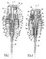
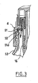
- the pump 1 shown on the Figures 1 and 2 is intended to be mounted on a neck 52 of a container 53, apparent on the figure 3 , containing a product P to be dispensed, for example a low viscosity product such as a perfume.
- This pump 1 comprises a fixed part 2 and a mobile assembly 3 that can move along an axis X with respect to the fixed part 2.
- the latter comprises a base portion 4 comprising a mounting skirt 5, threaded internally, intended to be secured to the neck 52 of the container 53 by screwing in the example.
- the base portion 4 could be otherwise attached to the container neck without departing from the scope of the present invention by snapping, gluing, welding or crimping for example.
- the fixed part 2 further comprises a pump body 16 defining with the moving assembly 3 a pumping chamber 17, of variable volume.
- the moving assembly 3 comprises a piston 30 made in one piece with a hollow rod 31 at the upper end of which is fixed a push-button 25.
- the mounting skirt 5 is extended upwards by a neck 7, surrounding a central portion 8 of the base portion 4.
- This central portion 8 comprises two tubular walls 9 and 12, coaxial, interconnected by an annular wall 11 to their upper end, and defines an annular groove open downwards, in which is engaged the pump body 16.
- the central portion 8 is connected at its lower end to the neck 7 by an annular wall 10 extending perpendicularly to the axis X.
- This passage 13 defines at its lower end a frustoconical surface 13a of axis X, diverging downwards, against which can sealingly supporting a corresponding frustoconical surface 31a of the rod 31, converging upwards, when the pump is at rest, as illustrated in FIG. figure 1 .
- the radially outermost tubular wall 9 has, on its radially inner side, a bead 14 for snap-fastening the pump body 16 to the base part 4, the pump body 16 having for this purpose at its end upper annular bead 23.
- the base portion 4 carries an annular seal 51 intended to be interposed between the annular wall 10 and the upper end of the neck 52 of the container 53, as illustrated in FIG. figure 3 .
- the radially inner portion 51a of the seal 51 normally engages against the pump body 16 to prevent the product contained in the container from flowing outwardly.
- the pump body 16 has in the example considered a cylindrical portion 16a of revolution about the axis X and has at its lower end a tip 18 for fixing a dip tube 19.
- the nozzle 18 defines the seat of a ball suction valve 20.
- the latter is retained in its housing by at least one lug 21 of the pump body 16.
- the pump body 16 has an opening 24, located in the example considered substantially halfway up the latter, and making it possible to put the pumping chamber 17 in communication with the inside. of the container when the mobile assembly 3 is at rest, the volume of the pumping chamber then being maximum.
- the pushbutton 25 comprises a dispensing orifice 26 made with a conventional swirling channel nozzle 27, attached to the rest of the push button, which allows the dispensing of the product P in the form of a spray.
- the rod 31 comprises a channel 29 allowing the product to gain this orifice 26.
- the piston 30 comprises first 40 and second 41 annular lips.
- the first lip 40 is of substantially frustoconical shape, diverging towards the bottom of the pumping chamber 14 and bears sealingly on the inner surface of the cylindrical portion 16a of the pump body 16. This first lip 40 is located above the opening 24 when the pump is in its rest position, as illustrated on the figure 1 .
- the second annular lip 41 is located above the first 40, and also applies sealingly to the inner surface of the cylindrical portion 16a of the pump body 16.
- This second lip 41 has in the example considered a shape arcuate, concave towards the inner surface of the body 16, and is applied by lower edges 41a and upper 42b to the body 16.
- the rod 31 is extended inferiorly by an end piece 32, hollow, closed at its lower end.
- This end piece 32 is for example fixed by snapping on the rod 31, and has an outer shoulder 33 on which bears at its upper end a helical spring 34 working in compression, which rests at its lower end on the bottom of the pump body 16.
- Passages 36 are made between the pumping chamber 17, outside the end piece 32, and the interior space 35 thereof, to allow the product contained in the pumping chamber 17 to gain the channel. 29 when the volume of the pumping chamber 17 decreases.
- the moving assembly 3 comprises, in the interior space 35, a shutter 42 movable between a closed position closing the channel 29 and a dispensing position allowing the product to flow in the channel 29 to the orifice 26.
- the shutter 42 comprises a tubular body 43, of axis X, closed at its upper end by a frustoconical portion 44 adapted to be applied against a seat formed in the rod 31, to close the channel 29 when the pump is at rest as shown on the figure 1 .
- the shutter 42 further comprises an annular lip 46 outside the tubular body 43, adapted to be applied on the inner surface of the end piece 32.
- This annular lip 46 has, when the pump is seen upside down, a frustoconical shape diverging upwards, and is positioned below the passages 36 communicating the interior space 35 with the pumping chamber 17.
- a helical spring 45 working in compression recalls the shutter 42 in its closed position at rest, as can be seen in FIG. figure 1 .
- This spring 45 is supported at its lower end against the bottom of the end piece 32 and at its upper end against the base of the lip 46.
- the air can be sucked into it by circulating between the neck 7 and the push button 25 and when the latter is depressed, in the clearance existing between the rod 31 and the tubular wall 12, between the latter and the pump body 16, between the annular wall 11 and the body 16, then between the tubular wall 9 and the pump body 16 and finally between the gasket 51 and the body 16.
- the air can circulate through diametrically opposed axial grooves formed in the bead 14.
- the radially inner portion 51a of the annular seal 51 can move slightly away from the pump body 16 , to allow the air flowing between the tubular wall 9 and the pump body 16 to gain inside the container, as can be seen on the figure 3 .
- the operation of the pump 1 is as follows.
- the user presses down on the push-button 25, and the moving assembly 3 moves relative to the pump body 16, so that the pressure of the product contained in the pumping chamber 17 increases, the ball 20 being pressed against its seat.
- the shutter 42 remains in its closed position of the channel 29 until the pressure of the product in the interior space 35 above the annular lip 46 is sufficient to overcome the return force of the spring 45.
- the first lip 40 isolates the pumping chamber 17 from the opening 24 and the second annular lip 41 isolates the opening 24 of the air intake passage.
- the air intake can be performed along the path 50, to compensate inside the container the volume of product taken by the pump 1.
- the pumping chamber 17 can fill through the opening 24 through the fact that the air can be evacuated by the plunger tube.
- the distribution of the product is carried out in the same way as in head up position.
- the pump body may notably comprise not one, but several openings 24.
Landscapes
- Reciprocating Pumps (AREA)
- Closures For Containers (AREA)
- Containers And Packaging Bodies Having A Special Means To Remove Contents (AREA)
Claims (15)
- Pumpe (1), die dazu bestimmt ist, auf einem Behälter festgelegt zu sein, die aufweist:- einen festgelegten Teil, der ein Pumpengehäuse bzw. einen Pumpenkörper (16) aufweist,- einen bewegbaren Aufbau (3) im Hinblick auf das Pumpengehäuse (16) und wobei dieser mit jenem eine Pumpenkammer mit einem veränderbaren Volumen (17) bestimmt,- zumindest eine Öffnung (24) in dem Pumpengehäuse, die es der Pumpenkammer ermöglicht, mit dem Inneren des Behälters in Verbindung zu treten, und die in der Weise geordnet ist, um einen Betrieb der Pumpe mit dem Kopf nach unten zu erlauben,- einen Durchgang zur Luftnachführung zwischen dem festgelegten Teil (2) und dem beweglichen Aufbau (3), wobei sich dieser Durchgang von der Öffnung (24) unterscheidet,- eine erste Lippe (40) die angeordnet ist, um nach der Verbringung des beweglichen Aufbaus von einer Ruheposition in dem Sinn der Verteilung von dem Produkt, in einer dichtenden Weise auf dem Pumpengehäuse (16) anzuliegen und um eine Verbindung über die Öffnung (24) zwischen dem Inneren des Behälters und der Pumpenkammer (17) zu verhindern,- eine zweite Lippe (41), die oberhalb der ersten angeordnet ist, wenn die Pumpe mit dem Kopf nach oben gesehen wird, wobei die zweite Lippe angeordnet ist, um zumindest wenn der bewegliche Aufbau in einer Bewegungsendposition in dem Pumpengehäuse ist, sich in einer dichtenden Weise auf dem Pumpengehäuse anzulegen und eine Verbindung quer durch das Innere des Pumpengehäuses und durch die Öffnung zwischen dem Inneren des Behälters und dem Äußeren zu verhindern,wobei die Pumpe dadurch gekennzeichnet ist, dass sie außerdem aufweist, ein Grundteil (4), das die Festlegung der Pumpe auf dem Behälter ermöglicht, wobei das Pumpengehäuse (16) auf diesem Grundteil festgelegt ist, und dadurch gekennzeichnet ist, dass der Durchgang zur Luftnachführung zumindest teilweise zwischen dem Grundteil (4) und dem Pumpengehäuse (16) ausgebildet ist.
- Pumpe nach dem voranstehenden Anspruch, dadurch gekennzeichnet, dass die eine von zumindest der ersten (40) und der zweiten (41) Lippe angeordnet ist, um dauerhaft auf dem Pumpengehäuse (16) anzuliegen, und dass bevorzugt die zwei Lippen dauerhaft auf dem Pumpengehäuse anliegen.
- Pumpe nach einem der voranstehenden Ansprüche, dadurch gekennzeichnet, dass die erste Lippe (40) eine genau kegelstumpfartige Form vorzuweisen hat, die in Richtung der Pumpenkammer divergent verläuft.
- Pumpe nach irgendeinem der voranstehenden Ansprüche, dadurch gekennzeichnet, dass die zweite Lippe (41) eine Bogenform vorzuweisen hat, die in Richtung der inneren Oberfläche des Pumengehäuses konkav ist, die über untere und obere Ränder auf dem Pumpengehäuse anliegt.
- Pumpe nach irgendeinem der voranstehenden Ansprüche, dadurch gekennzeichnet, dass der bewegbare Aufbau (3) einen Durchgang zum Auslassen von Produkt und einen Verschluss (42) aufweist, der angeordnet ist, um den Durchgang zu verschließen, wenn das Volumen der Pumpenkammer ansteigt, und um den Durchgang freizugeben, wenn das Volumen der Pumpenkammer abnimmt und falls der Druck des Produktes in der Pumpenkammer einen vorbestimmten Wert erreicht.
- Pumpe nach dem voranstehenden Anspruch, dadurch gekennzeichnet, dass der bewegliche Aufbau einen inneren Raum (35) aufweist, in welchen der Durchgang für den Auslass vom Produkt mündet und in welchem der Verschluss (42) geordnet ist.
- Pumpe nach einem der Ansprüche 5 und 6, dadurch gekennzeichnet, dass der Verschluss einen zylindrischen Körper (43) aufweist, der an seinem oberen Ende durch einen genau kegelstumpfförmigen Abschnitt (44) geschlossen wird, der dazu geeignet ist, um den Auslassdurchgang von dem Produkt zu verschließen.
- Pumpe nach dem voranstehenden Anspruch, dadurch gekennzeichnet, dass der Verschluss außerdem aufweist, eine ringförmige Lippe (46) an dem Äußeren des zylindrischen Körpers, die dazu geeignet ist, um in Anlage auf einer Wand, die den inneren Raum (39) begrenzt, zu kommen, wobei diese ringförmige Lippe, wenn die Pumpe mit dem Kopf nach oben beobachtet wird, eine genau kegelstumpfförmige Form vorzuweisen hat, die in Richtung des Kopfes divergiert die sich unterhalb von der oder den Durchgängen (36) befindet, die ein Verbindung des inneren Raumes (35) mit der Pumpenkammer herstellen.
- Pumpe nach einem der Ansprüche 6 bis 8, dadurch gekennzeichnet, dass der Verschluss in seine Position zum Verschließen durch ein elastisches Rückholelement (45), das in dem inneren Raum (35) angeordnet ist, zurückgeholt wird, wobei das elastische Rückholelement bevorzugt eine spiralförmige Feder ist, die über Kompression arbeitet.
- Pumpe nach irgendeinem der voranstehenden Ansprüche, dadurch gekennzeichnet, dass diese ein elastisches Rückholelement (34) aufweist, das dazu geeignet ist, um den beweglichen Aufbau in seine Ruheposition zurückzuholen.
- Pumpe nach dem voranstehenden Anspruch, dadurch gekennzeichnet, dass das elastische Rückholelement (34) in der Pumpenkammer (17) angeordnet ist.
- Pumpe nach einem der voranstehenden Ansprüche, dadurch gekennzeichnet, dass das Pumpengehäuse (16) ausgebildet ist, um die Festlegung von einem Tauchrohr (19) zu ermöglichen.
- Pumpe nach dem voranstehenden Anspruch, die eine Lüftungsklappe (20) aufeist, die sich schließt, wenn das Volumen der Pumpenkammer abnimmt und sich öffnet, wenn das Volumen der Pumpenkammer ansteigt, dadurch gekennzeichnet, dass die Klappe in einer Weise angeordnet ist, die eine Versorgung der Pumpenkammer mit Produkt durch das dazwischen liegende Tauchrohr ermöglicht, wenn die Pumpe mit dem Kopf nach oben verwendet wird.
- Pumpe nach irgendeinem der voranstehenden Ansprüche, dadurch gekennzeichnet, dass das Pumpengehäuse (16) auf dem Grundteil über Verrastung festgelegt ist.
- Behälter, der mit einer Pumpe nach irgendeinem der voranstehenden Ansprüche ausgestattet ist.
Applications Claiming Priority (2)
| Application Number | Priority Date | Filing Date | Title |
|---|---|---|---|
| FR0304591A FR2853697B1 (fr) | 2003-04-11 | 2003-04-11 | Pompe et recipient ainsi equipe |
| EP04290938A EP1466669B1 (de) | 2003-04-11 | 2004-04-08 | Pumpe zum Ausbringen eines Produkts in verschiedenen Sprühpositionen und entsprechender Behälter |
Related Parent Applications (2)
| Application Number | Title | Priority Date | Filing Date |
|---|---|---|---|
| EP04290938A Division EP1466669B1 (de) | 2003-04-11 | 2004-04-08 | Pumpe zum Ausbringen eines Produkts in verschiedenen Sprühpositionen und entsprechender Behälter |
| EP04290938.2 Division | 2004-04-08 |
Publications (3)
| Publication Number | Publication Date |
|---|---|
| EP1616632A2 EP1616632A2 (de) | 2006-01-18 |
| EP1616632A3 EP1616632A3 (de) | 2011-02-16 |
| EP1616632B1 true EP1616632B1 (de) | 2011-12-28 |
Family
ID=32865431
Family Applications (2)
| Application Number | Title | Priority Date | Filing Date |
|---|---|---|---|
| EP04290938A Expired - Lifetime EP1466669B1 (de) | 2003-04-11 | 2004-04-08 | Pumpe zum Ausbringen eines Produkts in verschiedenen Sprühpositionen und entsprechender Behälter |
| EP05023001A Expired - Lifetime EP1616632B1 (de) | 2003-04-11 | 2004-04-08 | Pumpe zum Ausbringen eines Produkts in verschiedenen Sprühpositionen und entsprechender Behälter |
Family Applications Before (1)
| Application Number | Title | Priority Date | Filing Date |
|---|---|---|---|
| EP04290938A Expired - Lifetime EP1466669B1 (de) | 2003-04-11 | 2004-04-08 | Pumpe zum Ausbringen eines Produkts in verschiedenen Sprühpositionen und entsprechender Behälter |
Country Status (8)
| Country | Link |
|---|---|
| EP (2) | EP1466669B1 (de) |
| JP (2) | JP4106352B2 (de) |
| CN (1) | CN1302968C (de) |
| AT (2) | ATE316826T1 (de) |
| BR (1) | BRPI0401658B1 (de) |
| DE (1) | DE602004000369T2 (de) |
| ES (2) | ES2257726T3 (de) |
| FR (1) | FR2853697B1 (de) |
Families Citing this family (7)
| Publication number | Priority date | Publication date | Assignee | Title |
|---|---|---|---|---|
| FR2913731B1 (fr) * | 2007-03-12 | 2013-08-09 | Valois Sas | Pompe de distribution de produit fluide et distributeur comportant une telle pompe |
| CN102092666A (zh) * | 2010-12-07 | 2011-06-15 | 黄瑞娟 | 一种分配器 |
| DE102011005820A1 (de) | 2011-03-18 | 2012-09-20 | Ing. Erich Pfeiffer Gmbh | Austragvorrichtung |
| CN102161025B (zh) * | 2011-04-01 | 2013-04-03 | 余姚晟祺塑业有限公司 | 能倒置使用的揿压式喷雾器 |
| CN103708093B (zh) * | 2013-12-13 | 2016-08-17 | 中山市美捷时包装制品有限公司 | 一种双弹簧乳液泵 |
| CN107458746B (zh) * | 2016-06-06 | 2020-08-11 | 丁要武 | 防溢液乳液泵 |
| CN114889977B (zh) * | 2022-06-30 | 2025-11-14 | 广东美捷时控股股份有限公司 | 一种预压式全塑喷雾泵 |
Family Cites Families (10)
| Publication number | Priority date | Publication date | Assignee | Title |
|---|---|---|---|---|
| US580948A (en) * | 1897-04-20 | montgomerie | ||
| JPS4712739Y1 (de) * | 1968-08-06 | 1972-05-11 | ||
| IT1038354B (it) * | 1975-05-22 | 1979-11-20 | Coster Tecnologie Speciali Spa | Dispositivo erogatore nebulizzatore ad azione pompante |
| JPS6031552B2 (ja) * | 1975-08-23 | 1985-07-23 | 博 近藤 | ばね蓄圧式噴霧ポンプ |
| JPS52106612U (de) * | 1977-02-15 | 1977-08-13 | ||
| NL179791C (nl) * | 1977-05-12 | 1986-11-17 | Yoshino Kogyosho Co Ltd | Zowel rechtop als in omgekeerde stand te gebruiken verstuiver. |
| FR2528122B1 (fr) * | 1982-06-04 | 1988-07-15 | Valois Sa | Pompe pour vaporisateur toutes positions |
| ES2011140A6 (es) * | 1988-10-10 | 1989-12-16 | Monturas Sa | Bomba pulverizadora. |
| FR2715585B1 (fr) * | 1994-01-28 | 1996-03-08 | Oreal | Ensemble de distribution d'un liquide, de façon quasi-continue, comportant une pompe et utilisation d'un tel ensemble pour la pulvérisation d'une laque capillaire. |
| JP2002273278A (ja) * | 2001-03-21 | 2002-09-24 | Yoshino Kogyosho Co Ltd | 合成樹脂製の蓄圧式液体噴出器 |
-
2003
- 2003-04-11 FR FR0304591A patent/FR2853697B1/fr not_active Expired - Fee Related
-
2004
- 2004-04-07 CN CNB2004100308659A patent/CN1302968C/zh not_active Expired - Lifetime
- 2004-04-08 AT AT04290938T patent/ATE316826T1/de not_active IP Right Cessation
- 2004-04-08 DE DE602004000369T patent/DE602004000369T2/de not_active Expired - Lifetime
- 2004-04-08 AT AT05023001T patent/ATE538877T1/de active
- 2004-04-08 BR BRPI0401658A patent/BRPI0401658B1/pt active IP Right Grant
- 2004-04-08 EP EP04290938A patent/EP1466669B1/de not_active Expired - Lifetime
- 2004-04-08 ES ES04290938T patent/ES2257726T3/es not_active Expired - Lifetime
- 2004-04-08 EP EP05023001A patent/EP1616632B1/de not_active Expired - Lifetime
- 2004-04-08 ES ES05023001T patent/ES2379176T3/es not_active Expired - Lifetime
- 2004-04-12 JP JP2004116457A patent/JP4106352B2/ja not_active Expired - Lifetime
-
2007
- 2007-11-20 JP JP2007300264A patent/JP5095357B2/ja not_active Expired - Lifetime
Also Published As
| Publication number | Publication date |
|---|---|
| BRPI0401658B1 (pt) | 2016-12-27 |
| ATE316826T1 (de) | 2006-02-15 |
| DE602004000369T2 (de) | 2006-10-12 |
| JP2008133828A (ja) | 2008-06-12 |
| JP2004316652A (ja) | 2004-11-11 |
| DE602004000369D1 (de) | 2006-04-13 |
| JP4106352B2 (ja) | 2008-06-25 |
| ES2379176T3 (es) | 2012-04-23 |
| EP1466669A1 (de) | 2004-10-13 |
| CN1535901A (zh) | 2004-10-13 |
| ATE538877T1 (de) | 2012-01-15 |
| BRPI0401658A (pt) | 2005-01-18 |
| EP1466669B1 (de) | 2006-02-01 |
| EP1616632A3 (de) | 2011-02-16 |
| JP5095357B2 (ja) | 2012-12-12 |
| FR2853697B1 (fr) | 2006-07-28 |
| EP1616632A2 (de) | 2006-01-18 |
| CN1302968C (zh) | 2007-03-07 |
| ES2257726T3 (es) | 2006-08-01 |
| FR2853697A1 (fr) | 2004-10-15 |
Similar Documents
| Publication | Publication Date | Title |
|---|---|---|
| EP1048590B1 (de) | Ventilbetätigungsvorrichtung und Einrichtung mit einer solchen Vorrichtung | |
| EP2006028B1 (de) | Pumpe zur Verteilung eines flüssigen Produkts mit verbesserter Zündung | |
| EP1588775B1 (de) | Verpackungs- und Abgabeeinheit eines Produktes, insbesondere eines kosmetischen Produktes | |
| FR2686377A1 (fr) | Pompe a precompression perfectionnee. | |
| EP0437131B1 (de) | Vordruck-Handpumpe zum zerstäuben einer Flüssigkeit, insbesondere eines Parfüms | |
| FR2773355A1 (fr) | Dispositif de conditionnement et de distribution comportant un reservoir rempli sous vide et procede de fabrication | |
| EP0688609A1 (de) | Vordruck-Handpumpe zur Zerstäuben einer Flüssigkeit und Abgabevorrichtung mit einer solchen Pumpe | |
| EP1002735B1 (de) | Pumpe und damit ausgerüsteter Behälter | |
| EP0747131B1 (de) | Pumpenvorrichtung zum Entnehmen einer Flüssigkeit aus einem Behälter und zu deren Zerstäubung | |
| EP1205255B1 (de) | Pumpe zur Abgabe eines Produktes, insbesondere eines kosmetischen Mittels oder eines Pflegemittels | |
| FR2727162A1 (fr) | Pompe manuelle a precompression pour la pulverisation d'un liquide et ensemble de distribution equipe d'une telle pompe | |
| FR2800132A1 (fr) | POMPE DESTINEE A EQUIPER UN RECIPIENT, COMPORTANT UNE MEMBRANE ELASTIQUEMENT DEFORMABLE A l'EXTERIEUR DE LA CHAMBRE DE POMPAGE | |
| EP1127624B1 (de) | Pumpe mit einer als Feder wirkenden Membrane and Behälter mit einer solchen Pumpe | |
| EP1616632B1 (de) | Pumpe zum Ausbringen eines Produkts in verschiedenen Sprühpositionen und entsprechender Behälter | |
| EP0544549B1 (de) | Pumpe zur Förderung von einem flüssigen oder pastösen Produkt, und Ausgabebehälter mit einer solchen Pumpe | |
| FR2785594A1 (fr) | Valve, recharge equipee d'une telle valve, et ensemble de distribution equipe d'une telle valve | |
| EP1430957B1 (de) | Behälter mit einer Pumpe | |
| CA2317930C (fr) | Pompe destinee a equiper un recipient | |
| FR2814727A1 (fr) | Valve destinee a equiper un dispositif pour la distribution sous pression d'un produit, et dispositif ainsi equipe | |
| CA2316673C (fr) | Pompe a membrane pour recipient | |
| EP1960117B1 (de) | Pumpe mit einer gleitenden buchse | |
| WO1992001183A1 (fr) | Clapet pour pulverisateur |
Legal Events
| Date | Code | Title | Description |
|---|---|---|---|
| PUAI | Public reference made under article 153(3) epc to a published international application that has entered the european phase |
Free format text: ORIGINAL CODE: 0009012 |
|
| 17P | Request for examination filed |
Effective date: 20051021 |
|
| AC | Divisional application: reference to earlier application |
Ref document number: 1466669 Country of ref document: EP Kind code of ref document: P |
|
| AK | Designated contracting states |
Kind code of ref document: A2 Designated state(s): AT BE BG CH CY CZ DE DK EE ES FI FR GB GR HU IE IT LI LU MC NL PL PT RO SE SI SK TR |
|
| PUAL | Search report despatched |
Free format text: ORIGINAL CODE: 0009013 |
|
| AK | Designated contracting states |
Kind code of ref document: A3 Designated state(s): AT BE BG CH CY CZ DE DK EE ES FI FR GB GR HU IE IT LI LU MC NL PL PT RO SE SI SK TR |
|
| 17Q | First examination report despatched |
Effective date: 20110221 |
|
| GRAP | Despatch of communication of intention to grant a patent |
Free format text: ORIGINAL CODE: EPIDOSNIGR1 |
|
| RIC1 | Information provided on ipc code assigned before grant |
Ipc: B05B 11/00 20060101AFI20110620BHEP |
|
| AKX | Designation fees paid |
Designated state(s): AT BE BG CH CY CZ DE DK EE ES FI FR GB GR HU IE IT LI LU MC NL PL PT RO SE SI SK TR |
|
| GRAS | Grant fee paid |
Free format text: ORIGINAL CODE: EPIDOSNIGR3 |
|
| GRAA | (expected) grant |
Free format text: ORIGINAL CODE: 0009210 |
|
| AC | Divisional application: reference to earlier application |
Ref document number: 1466669 Country of ref document: EP Kind code of ref document: P |
|
| AK | Designated contracting states |
Kind code of ref document: B1 Designated state(s): AT BE BG CH CY CZ DE DK EE ES FI FR GB GR HU IE IT LI LU MC NL PL PT RO SE SI SK TR |
|
| REG | Reference to a national code |
Ref country code: GB Ref legal event code: FG4D Free format text: NOT ENGLISH |
|
| REG | Reference to a national code |
Ref country code: CH Ref legal event code: EP |
|
| REG | Reference to a national code |
Ref country code: AT Ref legal event code: REF Ref document number: 538877 Country of ref document: AT Kind code of ref document: T Effective date: 20120115 |
|
| REG | Reference to a national code |
Ref country code: IE Ref legal event code: FG4D |
|
| REG | Reference to a national code |
Ref country code: DE Ref legal event code: R096 Ref document number: 602004035920 Country of ref document: DE Effective date: 20120301 |
|
| REG | Reference to a national code |
Ref country code: NL Ref legal event code: VDEP Effective date: 20111228 |
|
| REG | Reference to a national code |
Ref country code: ES Ref legal event code: FG2A Ref document number: 2379176 Country of ref document: ES Kind code of ref document: T3 Effective date: 20120423 |
|
| PG25 | Lapsed in a contracting state [announced via postgrant information from national office to epo] |
Ref country code: SE Free format text: LAPSE BECAUSE OF FAILURE TO SUBMIT A TRANSLATION OF THE DESCRIPTION OR TO PAY THE FEE WITHIN THE PRESCRIBED TIME-LIMIT Effective date: 20111228 Ref country code: GR Free format text: LAPSE BECAUSE OF FAILURE TO SUBMIT A TRANSLATION OF THE DESCRIPTION OR TO PAY THE FEE WITHIN THE PRESCRIBED TIME-LIMIT Effective date: 20120329 Ref country code: SI Free format text: LAPSE BECAUSE OF FAILURE TO SUBMIT A TRANSLATION OF THE DESCRIPTION OR TO PAY THE FEE WITHIN THE PRESCRIBED TIME-LIMIT Effective date: 20111228 |
|
| PG25 | Lapsed in a contracting state [announced via postgrant information from national office to epo] |
Ref country code: CY Free format text: LAPSE BECAUSE OF FAILURE TO SUBMIT A TRANSLATION OF THE DESCRIPTION OR TO PAY THE FEE WITHIN THE PRESCRIBED TIME-LIMIT Effective date: 20111228 |
|
| REG | Reference to a national code |
Ref country code: IE Ref legal event code: FD4D |
|
| PG25 | Lapsed in a contracting state [announced via postgrant information from national office to epo] |
Ref country code: BG Free format text: LAPSE BECAUSE OF FAILURE TO SUBMIT A TRANSLATION OF THE DESCRIPTION OR TO PAY THE FEE WITHIN THE PRESCRIBED TIME-LIMIT Effective date: 20120328 Ref country code: IE Free format text: LAPSE BECAUSE OF FAILURE TO SUBMIT A TRANSLATION OF THE DESCRIPTION OR TO PAY THE FEE WITHIN THE PRESCRIBED TIME-LIMIT Effective date: 20111228 Ref country code: EE Free format text: LAPSE BECAUSE OF FAILURE TO SUBMIT A TRANSLATION OF THE DESCRIPTION OR TO PAY THE FEE WITHIN THE PRESCRIBED TIME-LIMIT Effective date: 20111228 Ref country code: SK Free format text: LAPSE BECAUSE OF FAILURE TO SUBMIT A TRANSLATION OF THE DESCRIPTION OR TO PAY THE FEE WITHIN THE PRESCRIBED TIME-LIMIT Effective date: 20111228 Ref country code: NL Free format text: LAPSE BECAUSE OF FAILURE TO SUBMIT A TRANSLATION OF THE DESCRIPTION OR TO PAY THE FEE WITHIN THE PRESCRIBED TIME-LIMIT Effective date: 20111228 Ref country code: CZ Free format text: LAPSE BECAUSE OF FAILURE TO SUBMIT A TRANSLATION OF THE DESCRIPTION OR TO PAY THE FEE WITHIN THE PRESCRIBED TIME-LIMIT Effective date: 20111228 |
|
| PG25 | Lapsed in a contracting state [announced via postgrant information from national office to epo] |
Ref country code: RO Free format text: LAPSE BECAUSE OF FAILURE TO SUBMIT A TRANSLATION OF THE DESCRIPTION OR TO PAY THE FEE WITHIN THE PRESCRIBED TIME-LIMIT Effective date: 20111228 Ref country code: PT Free format text: LAPSE BECAUSE OF FAILURE TO SUBMIT A TRANSLATION OF THE DESCRIPTION OR TO PAY THE FEE WITHIN THE PRESCRIBED TIME-LIMIT Effective date: 20120430 Ref country code: PL Free format text: LAPSE BECAUSE OF FAILURE TO SUBMIT A TRANSLATION OF THE DESCRIPTION OR TO PAY THE FEE WITHIN THE PRESCRIBED TIME-LIMIT Effective date: 20111228 |
|
| REG | Reference to a national code |
Ref country code: AT Ref legal event code: MK05 Ref document number: 538877 Country of ref document: AT Kind code of ref document: T Effective date: 20111228 |
|
| BERE | Be: lapsed |
Owner name: L'OREAL Effective date: 20120430 |
|
| PG25 | Lapsed in a contracting state [announced via postgrant information from national office to epo] |
Ref country code: DK Free format text: LAPSE BECAUSE OF FAILURE TO SUBMIT A TRANSLATION OF THE DESCRIPTION OR TO PAY THE FEE WITHIN THE PRESCRIBED TIME-LIMIT Effective date: 20111228 |
|
| PLBE | No opposition filed within time limit |
Free format text: ORIGINAL CODE: 0009261 |
|
| STAA | Information on the status of an ep patent application or granted ep patent |
Free format text: STATUS: NO OPPOSITION FILED WITHIN TIME LIMIT |
|
| PG25 | Lapsed in a contracting state [announced via postgrant information from national office to epo] |
Ref country code: MC Free format text: LAPSE BECAUSE OF NON-PAYMENT OF DUE FEES Effective date: 20120430 |
|
| REG | Reference to a national code |
Ref country code: CH Ref legal event code: PL |
|
| 26N | No opposition filed |
Effective date: 20121001 |
|
| REG | Reference to a national code |
Ref country code: DE Ref legal event code: R097 Ref document number: 602004035920 Country of ref document: DE Effective date: 20121001 |
|
| PG25 | Lapsed in a contracting state [announced via postgrant information from national office to epo] |
Ref country code: CH Free format text: LAPSE BECAUSE OF NON-PAYMENT OF DUE FEES Effective date: 20120430 Ref country code: AT Free format text: LAPSE BECAUSE OF FAILURE TO SUBMIT A TRANSLATION OF THE DESCRIPTION OR TO PAY THE FEE WITHIN THE PRESCRIBED TIME-LIMIT Effective date: 20111228 Ref country code: BE Free format text: LAPSE BECAUSE OF NON-PAYMENT OF DUE FEES Effective date: 20120430 Ref country code: LI Free format text: LAPSE BECAUSE OF NON-PAYMENT OF DUE FEES Effective date: 20120430 |
|
| PG25 | Lapsed in a contracting state [announced via postgrant information from national office to epo] |
Ref country code: FI Free format text: LAPSE BECAUSE OF FAILURE TO SUBMIT A TRANSLATION OF THE DESCRIPTION OR TO PAY THE FEE WITHIN THE PRESCRIBED TIME-LIMIT Effective date: 20111228 |
|
| PG25 | Lapsed in a contracting state [announced via postgrant information from national office to epo] |
Ref country code: TR Free format text: LAPSE BECAUSE OF FAILURE TO SUBMIT A TRANSLATION OF THE DESCRIPTION OR TO PAY THE FEE WITHIN THE PRESCRIBED TIME-LIMIT Effective date: 20111228 |
|
| PG25 | Lapsed in a contracting state [announced via postgrant information from national office to epo] |
Ref country code: LU Free format text: LAPSE BECAUSE OF NON-PAYMENT OF DUE FEES Effective date: 20120408 |
|
| PG25 | Lapsed in a contracting state [announced via postgrant information from national office to epo] |
Ref country code: HU Free format text: LAPSE BECAUSE OF FAILURE TO SUBMIT A TRANSLATION OF THE DESCRIPTION OR TO PAY THE FEE WITHIN THE PRESCRIBED TIME-LIMIT Effective date: 20040408 |
|
| REG | Reference to a national code |
Ref country code: FR Ref legal event code: PLFP Year of fee payment: 13 |
|
| REG | Reference to a national code |
Ref country code: FR Ref legal event code: PLFP Year of fee payment: 14 |
|
| REG | Reference to a national code |
Ref country code: FR Ref legal event code: PLFP Year of fee payment: 15 |
|
| PGFP | Annual fee paid to national office [announced via postgrant information from national office to epo] |
Ref country code: FR Payment date: 20230309 Year of fee payment: 20 |
|
| PGFP | Annual fee paid to national office [announced via postgrant information from national office to epo] |
Ref country code: IT Payment date: 20230310 Year of fee payment: 20 Ref country code: GB Payment date: 20230302 Year of fee payment: 20 |
|
| PGFP | Annual fee paid to national office [announced via postgrant information from national office to epo] |
Ref country code: ES Payment date: 20230512 Year of fee payment: 20 Ref country code: DE Payment date: 20230307 Year of fee payment: 20 |
|
| REG | Reference to a national code |
Ref country code: DE Ref legal event code: R071 Ref document number: 602004035920 Country of ref document: DE |
|
| REG | Reference to a national code |
Ref country code: ES Ref legal event code: FD2A Effective date: 20240429 |
|
| REG | Reference to a national code |
Ref country code: GB Ref legal event code: PE20 Expiry date: 20240407 |
|
| PG25 | Lapsed in a contracting state [announced via postgrant information from national office to epo] |
Ref country code: GB Free format text: LAPSE BECAUSE OF EXPIRATION OF PROTECTION Effective date: 20240407 |
|
| PG25 | Lapsed in a contracting state [announced via postgrant information from national office to epo] |
Ref country code: ES Free format text: LAPSE BECAUSE OF EXPIRATION OF PROTECTION Effective date: 20240409 |
|
| PG25 | Lapsed in a contracting state [announced via postgrant information from national office to epo] |
Ref country code: GB Free format text: LAPSE BECAUSE OF EXPIRATION OF PROTECTION Effective date: 20240407 Ref country code: ES Free format text: LAPSE BECAUSE OF EXPIRATION OF PROTECTION Effective date: 20240409 |