EP0716004B1 - Porte pivotante et coulissante pour véhicules de transport de personnes - Google Patents
Porte pivotante et coulissante pour véhicules de transport de personnes Download PDFInfo
- Publication number
- EP0716004B1 EP0716004B1 EP95119189A EP95119189A EP0716004B1 EP 0716004 B1 EP0716004 B1 EP 0716004B1 EP 95119189 A EP95119189 A EP 95119189A EP 95119189 A EP95119189 A EP 95119189A EP 0716004 B1 EP0716004 B1 EP 0716004B1
- Authority
- EP
- European Patent Office
- Prior art keywords
- door
- support member
- door leaf
- sliding door
- link connection
- Prior art date
- Legal status (The legal status is an assumption and is not a legal conclusion. Google has not performed a legal analysis and makes no representation as to the accuracy of the status listed.)
- Expired - Lifetime
Links
Images


Classifications
-
- B—PERFORMING OPERATIONS; TRANSPORTING
- B61—RAILWAYS
- B61D—BODY DETAILS OR KINDS OF RAILWAY VEHICLES
- B61D19/00—Door arrangements specially adapted for rail vehicles
- B61D19/02—Door arrangements specially adapted for rail vehicles for carriages
-
- B—PERFORMING OPERATIONS; TRANSPORTING
- B61—RAILWAYS
- B61D—BODY DETAILS OR KINDS OF RAILWAY VEHICLES
- B61D19/00—Door arrangements specially adapted for rail vehicles
- B61D19/003—Door arrangements specially adapted for rail vehicles characterised by the movements of the door
- B61D19/008—Door arrangements specially adapted for rail vehicles characterised by the movements of the door both swinging and sliding
-
- E—FIXED CONSTRUCTIONS
- E05—LOCKS; KEYS; WINDOW OR DOOR FITTINGS; SAFES
- E05D—HINGES OR SUSPENSION DEVICES FOR DOORS, WINDOWS OR WINGS
- E05D15/00—Suspension arrangements for wings
- E05D15/06—Suspension arrangements for wings for wings sliding horizontally more or less in their own plane
- E05D15/10—Suspension arrangements for wings for wings sliding horizontally more or less in their own plane movable out of one plane into a second parallel plane
- E05D15/1042—Suspension arrangements for wings for wings sliding horizontally more or less in their own plane movable out of one plane into a second parallel plane with transversely moving carriage
- E05D15/1044—Suspension arrangements for wings for wings sliding horizontally more or less in their own plane movable out of one plane into a second parallel plane with transversely moving carriage specially adapted for use in railway-cars or mass transit vehicles
-
- E—FIXED CONSTRUCTIONS
- E05—LOCKS; KEYS; WINDOW OR DOOR FITTINGS; SAFES
- E05D—HINGES OR SUSPENSION DEVICES FOR DOORS, WINDOWS OR WINGS
- E05D15/00—Suspension arrangements for wings
- E05D15/06—Suspension arrangements for wings for wings sliding horizontally more or less in their own plane
- E05D15/10—Suspension arrangements for wings for wings sliding horizontally more or less in their own plane movable out of one plane into a second parallel plane
- E05D15/1065—Suspension arrangements for wings for wings sliding horizontally more or less in their own plane movable out of one plane into a second parallel plane with transversely moving track
- E05D15/1068—Suspension arrangements for wings for wings sliding horizontally more or less in their own plane movable out of one plane into a second parallel plane with transversely moving track specially adapted for use in railway-cars or mass transit vehicles
-
- E—FIXED CONSTRUCTIONS
- E05—LOCKS; KEYS; WINDOW OR DOOR FITTINGS; SAFES
- E05F—DEVICES FOR MOVING WINGS INTO OPEN OR CLOSED POSITION; CHECKS FOR WINGS; WING FITTINGS NOT OTHERWISE PROVIDED FOR, CONCERNED WITH THE FUNCTIONING OF THE WING
- E05F15/00—Power-operated mechanisms for wings
- E05F15/60—Power-operated mechanisms for wings using electrical actuators
- E05F15/603—Power-operated mechanisms for wings using electrical actuators using rotary electromotors
- E05F15/632—Power-operated mechanisms for wings using electrical actuators using rotary electromotors for horizontally-sliding wings
- E05F15/643—Power-operated mechanisms for wings using electrical actuators using rotary electromotors for horizontally-sliding wings operated by flexible elongated pulling elements, e.g. belts, chains or cables
- E05F15/646—Power-operated mechanisms for wings using electrical actuators using rotary electromotors for horizontally-sliding wings operated by flexible elongated pulling elements, e.g. belts, chains or cables allowing or involving a secondary movement of the wing, e.g. rotational or transversal
-
- E—FIXED CONSTRUCTIONS
- E05—LOCKS; KEYS; WINDOW OR DOOR FITTINGS; SAFES
- E05D—HINGES OR SUSPENSION DEVICES FOR DOORS, WINDOWS OR WINGS
- E05D15/00—Suspension arrangements for wings
- E05D15/06—Suspension arrangements for wings for wings sliding horizontally more or less in their own plane
- E05D15/10—Suspension arrangements for wings for wings sliding horizontally more or less in their own plane movable out of one plane into a second parallel plane
- E05D15/1005—Suspension arrangements for wings for wings sliding horizontally more or less in their own plane movable out of one plane into a second parallel plane the wing being supported on arms movable in horizontal planes
- E05D15/1007—Suspension arrangements for wings for wings sliding horizontally more or less in their own plane movable out of one plane into a second parallel plane the wing being supported on arms movable in horizontal planes specially adapted for use in railway-cars or mass transit vehicles
-
- E—FIXED CONSTRUCTIONS
- E05—LOCKS; KEYS; WINDOW OR DOOR FITTINGS; SAFES
- E05D—HINGES OR SUSPENSION DEVICES FOR DOORS, WINDOWS OR WINGS
- E05D15/00—Suspension arrangements for wings
- E05D15/06—Suspension arrangements for wings for wings sliding horizontally more or less in their own plane
- E05D15/10—Suspension arrangements for wings for wings sliding horizontally more or less in their own plane movable out of one plane into a second parallel plane
- E05D2015/1028—Suspension arrangements for wings for wings sliding horizontally more or less in their own plane movable out of one plane into a second parallel plane with only the wing moving transversely
- E05D2015/1031—Suspension arrangements for wings for wings sliding horizontally more or less in their own plane movable out of one plane into a second parallel plane with only the wing moving transversely the wing supported on arms extending from the carriage
- E05D2015/1034—Suspension arrangements for wings for wings sliding horizontally more or less in their own plane movable out of one plane into a second parallel plane with only the wing moving transversely the wing supported on arms extending from the carriage the carriage having means for preventing rotation of the wing
-
- E—FIXED CONSTRUCTIONS
- E05—LOCKS; KEYS; WINDOW OR DOOR FITTINGS; SAFES
- E05D—HINGES OR SUSPENSION DEVICES FOR DOORS, WINDOWS OR WINGS
- E05D15/00—Suspension arrangements for wings
- E05D15/06—Suspension arrangements for wings for wings sliding horizontally more or less in their own plane
- E05D15/10—Suspension arrangements for wings for wings sliding horizontally more or less in their own plane movable out of one plane into a second parallel plane
- E05D15/1042—Suspension arrangements for wings for wings sliding horizontally more or less in their own plane movable out of one plane into a second parallel plane with transversely moving carriage
- E05D2015/1055—Suspension arrangements for wings for wings sliding horizontally more or less in their own plane movable out of one plane into a second parallel plane with transversely moving carriage with slanted or curved track sections or cams
- E05D2015/1057—Suspension arrangements for wings for wings sliding horizontally more or less in their own plane movable out of one plane into a second parallel plane with transversely moving carriage with slanted or curved track sections or cams the carriage swinging or rotating in those track sections
-
- E—FIXED CONSTRUCTIONS
- E05—LOCKS; KEYS; WINDOW OR DOOR FITTINGS; SAFES
- E05D—HINGES OR SUSPENSION DEVICES FOR DOORS, WINDOWS OR WINGS
- E05D15/00—Suspension arrangements for wings
- E05D15/06—Suspension arrangements for wings for wings sliding horizontally more or less in their own plane
- E05D15/10—Suspension arrangements for wings for wings sliding horizontally more or less in their own plane movable out of one plane into a second parallel plane
- E05D15/1065—Suspension arrangements for wings for wings sliding horizontally more or less in their own plane movable out of one plane into a second parallel plane with transversely moving track
- E05D2015/1084—Suspension arrangements for wings for wings sliding horizontally more or less in their own plane movable out of one plane into a second parallel plane with transversely moving track the carriage being directly linked to the fixed frame, e.g. slidingly
- E05D2015/1086—Suspension arrangements for wings for wings sliding horizontally more or less in their own plane movable out of one plane into a second parallel plane with transversely moving track the carriage being directly linked to the fixed frame, e.g. slidingly swingingly, e.g. on arms
-
- E—FIXED CONSTRUCTIONS
- E05—LOCKS; KEYS; WINDOW OR DOOR FITTINGS; SAFES
- E05Y—INDEXING SCHEME RELATING TO HINGES OR OTHER SUSPENSION DEVICES FOR DOORS, WINDOWS OR WINGS AND DEVICES FOR MOVING WINGS INTO OPEN OR CLOSED POSITION, CHECKS FOR WINGS AND WING FITTINGS NOT OTHERWISE PROVIDED FOR, CONCERNED WITH THE FUNCTIONING OF THE WING
- E05Y2201/00—Constructional elements; Accessories therefore
- E05Y2201/20—Brakes; Disengaging means, e.g. clutches; Holders, e.g. locks; Stops; Accessories therefore
- E05Y2201/218—Holders
- E05Y2201/22—Locks
-
- E—FIXED CONSTRUCTIONS
- E05—LOCKS; KEYS; WINDOW OR DOOR FITTINGS; SAFES
- E05Y—INDEXING SCHEME RELATING TO HINGES OR OTHER SUSPENSION DEVICES FOR DOORS, WINDOWS OR WINGS AND DEVICES FOR MOVING WINGS INTO OPEN OR CLOSED POSITION, CHECKS FOR WINGS AND WING FITTINGS NOT OTHERWISE PROVIDED FOR, CONCERNED WITH THE FUNCTIONING OF THE WING
- E05Y2201/00—Constructional elements; Accessories therefore
- E05Y2201/20—Brakes; Disengaging means, e.g. clutches; Holders, e.g. locks; Stops; Accessories therefore
- E05Y2201/23—Actuation thereof
- E05Y2201/232—Actuation thereof by automatically acting means
- E05Y2201/236—Actuation thereof by automatically acting means using force or torque
- E05Y2201/238—Actuation thereof by automatically acting means using force or torque reaction force or torque
-
- E—FIXED CONSTRUCTIONS
- E05—LOCKS; KEYS; WINDOW OR DOOR FITTINGS; SAFES
- E05Y—INDEXING SCHEME RELATING TO HINGES OR OTHER SUSPENSION DEVICES FOR DOORS, WINDOWS OR WINGS AND DEVICES FOR MOVING WINGS INTO OPEN OR CLOSED POSITION, CHECKS FOR WINGS AND WING FITTINGS NOT OTHERWISE PROVIDED FOR, CONCERNED WITH THE FUNCTIONING OF THE WING
- E05Y2201/00—Constructional elements; Accessories therefore
- E05Y2201/40—Motors; Magnets; Springs; Weights; Accessories therefore
- E05Y2201/43—Motors
- E05Y2201/434—Electromotors; Details thereof
-
- E—FIXED CONSTRUCTIONS
- E05—LOCKS; KEYS; WINDOW OR DOOR FITTINGS; SAFES
- E05Y—INDEXING SCHEME RELATING TO HINGES OR OTHER SUSPENSION DEVICES FOR DOORS, WINDOWS OR WINGS AND DEVICES FOR MOVING WINGS INTO OPEN OR CLOSED POSITION, CHECKS FOR WINGS AND WING FITTINGS NOT OTHERWISE PROVIDED FOR, CONCERNED WITH THE FUNCTIONING OF THE WING
- E05Y2600/00—Mounting or coupling arrangements for elements provided for in this subclass
- E05Y2600/10—Adjustable or movable
- E05Y2600/11—Adjustable or movable by automatically acting means
-
- E—FIXED CONSTRUCTIONS
- E05—LOCKS; KEYS; WINDOW OR DOOR FITTINGS; SAFES
- E05Y—INDEXING SCHEME RELATING TO HINGES OR OTHER SUSPENSION DEVICES FOR DOORS, WINDOWS OR WINGS AND DEVICES FOR MOVING WINGS INTO OPEN OR CLOSED POSITION, CHECKS FOR WINGS AND WING FITTINGS NOT OTHERWISE PROVIDED FOR, CONCERNED WITH THE FUNCTIONING OF THE WING
- E05Y2600/00—Mounting or coupling arrangements for elements provided for in this subclass
- E05Y2600/10—Adjustable or movable
- E05Y2600/30—Adjustable or movable characterised by the type of motion
- E05Y2600/32—Rotary motion
- E05Y2600/324—Rotary motion around a vertical axis
-
- E—FIXED CONSTRUCTIONS
- E05—LOCKS; KEYS; WINDOW OR DOOR FITTINGS; SAFES
- E05Y—INDEXING SCHEME RELATING TO HINGES OR OTHER SUSPENSION DEVICES FOR DOORS, WINDOWS OR WINGS AND DEVICES FOR MOVING WINGS INTO OPEN OR CLOSED POSITION, CHECKS FOR WINGS AND WING FITTINGS NOT OTHERWISE PROVIDED FOR, CONCERNED WITH THE FUNCTIONING OF THE WING
- E05Y2800/00—Details, accessories and auxiliary operations not otherwise provided for
- E05Y2800/73—Single use of elements
-
- E—FIXED CONSTRUCTIONS
- E05—LOCKS; KEYS; WINDOW OR DOOR FITTINGS; SAFES
- E05Y—INDEXING SCHEME RELATING TO HINGES OR OTHER SUSPENSION DEVICES FOR DOORS, WINDOWS OR WINGS AND DEVICES FOR MOVING WINGS INTO OPEN OR CLOSED POSITION, CHECKS FOR WINGS AND WING FITTINGS NOT OTHERWISE PROVIDED FOR, CONCERNED WITH THE FUNCTIONING OF THE WING
- E05Y2900/00—Application of doors, windows, wings or fittings thereof
- E05Y2900/50—Application of doors, windows, wings or fittings thereof for vehicles
- E05Y2900/51—Application of doors, windows, wings or fittings thereof for vehicles for railway cars or mass transit vehicles
Definitions
- the invention relates to a pivoting sliding door for Passenger vehicles, in particular Rail vehicles, with the features from the generic term of claim 1.
- Such a pivoting sliding door is for example described in DE 32 31 181 A1.
- Swivel sliding door is between the door leaf and the Support member arranged another swivel arm, so that the door leaf as a result of the pivoting movement the guidance by parallelogram handlebars in parallel is led itself.
- swing sliding doors desirable to add the door leaf itself Start of the opening movement additionally by a vertical one Swivel axis slightly so that the trailing edge the door leaf right at the beginning of the opening movement comes out of the door frame and with it the sliding movement can also begin.
- Swivel sliding door is for example in EP 0 320 591 A2.
- the sliding element itself is the guide element two cranks with vertical crank axes across pivotable to the level of the door leaf and the additional Swiveling the door leaf around the vertical Axis is reached by putting the cranks together with a connecting, rigid, the guide element supporting coupling link and with the door frame firmly connected crank pin with a four-bar link form opposite cranks.
- the invention has for its object a Swivel sliding door with the features from the generic term of claim 1 so that a Swiveling the door leaf even at the start of the Opening movement around a vertical axis is possible without the guide element and thus if necessary, the drive devices are also pivoted out have to be, i.e. it should make it possible this additional pivoting of the door leaf with the least possible design effort and to achieve less space. Furthermore should it may be possible to pivot this additional Door leaf from the longitudinal movement of the door leaf to derive.
- the basic idea of the invention is that Door leaf with the support member does not have an additional Swivel arm, but via a two-part link connection to connect and during a first Section of the opening movement in the longitudinal direction a relative pivot between the two parts perform the handlebar connection such that the position of the coupling point of the handlebar connection in Reference to the axis of rotation arranged on the support member Swivel arm changes and thus the door leaf one additional pivoting movement is given.
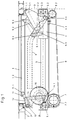
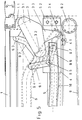
- FIG. 1 to 4 show one in a not shown Vehicle built-in sliding door as well a device for moving them in a first Embodiment. It is first of all based on FIG. 1 to 4 the basic structure of the swivel sliding door explained. To maintain clarity, in 1 to 4 details, which the control of the Relative pivoting of the parts of the explained below concern two-part linkage, not shown yet. They are the subject of Fig. 5 and 6.
- the door leaf 1 is connected to a swivel arm 3 Support member 4 connected, which for example as a ball sleeve can be formed and on a round rod trained horizontally in the vehicle longitudinal direction extending guide element 5 guided is.
- the guide element 5 is via fastening devices 5.1 and 5.2 fixed to the door frame 2 connected.
- the swivel arm 3 is fixed Approach 1.1 on the door leaf 1 via a vertical Axis of rotation 3.1 and with the support member 4 via a vertical Axis of rotation 3.2 connected.
- On the swivel arm 3 is a guide lever 3.3, which is a control roller 3.4 carries which in a firmly with the door frame 2 connected guide rail 6 engages that runs parallel to the longitudinal direction of the vehicle and on one end is led inside.
- the door drive device has an electric motor 7 with an output shaft 7.1, on the one Output gear 8.1 is arranged, which one along of the guide element 5 guided rotating toothed belt 8 drives that on the opposite of the motor 7 End runs over a pulley 8.2.
- the Support member 4 is connected via a connecting element 4.1 connected to the toothed belt 8.
- a is at the upper end of the door tree tube 10 Swivel lever 12 arranged, which via a coupling rod 14 articulated at a point 14.1 of a gear wheel 15 with which it forms a crank mechanism.
- the Gear 15 engages a gear 7.2, which is fixed with the housing rotatably mounted on the door frame 2
- Electric motor 7 is connected and its axis of rotation coaxial to the axis of the output shaft 7.1 of the electric motor 7 runs (see Fig. 4).
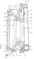
- FIG. 5 is an enlarged representation compared to FIG. 1 the right part of the closed in Fig. 1 Shown sliding door and it can be seen that in this embodiment the articulated on the support member 4 Part 9.1 of the two-part link connection is designed as a two-armed lever, one of which End with the other part 9.2 of the handlebar connection is connected, while the other end 9.6 another Guide role 9.7, which in one with the Door frame 2 firmly connected second guide rail 16 is running.
- this second one Guide rail in its first section initially a slight curve down and then another slight curvature upwards, after which it is in the vehicle longitudinal direction is continued.
- the two-piece link connection 9.1-9.2 is how 5, constructed so that when closed Door the axes of action of the swivel arm 3 and the part 9.2 connected to the door leaf Handlebar connection run essentially parallel.
- the door is opened when the drive motor is actuated 7 the support member 4 on the toothed belt 8 in motion offset along the guide element 5.
- the swivel arm 3 and via the articulation point 9.5 the two-part link connection taken away.
- the leadership role 3.4 runs in the first guide rail 6, so that Swivel arm 3 imprinted a swivel movement to the outside becomes.
- the leading role 9.7 runs in the second Guide rail 16.
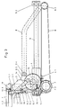
- FIG. 6 is a variant of the device for Control of the pivoting of the articulated on the support member 4 Part 9.1 of the two-part link connection described.
- Fig. 6 all parts are identical 1 to 4 corresponding parts with the same Reference numerals as indicated there, while Parts that function as variants of parts Fig. 5 correspond, each with an apostrophe are provided.
- a second lever arm 9.6 ' carries a guide role 9.7 '.
- a guide roller 9.8 ' is also arranged on part 9.1'.
- the two guide rollers 9.7 'and 9.8' lie positively on the guide surface of a cam 17 on the vertical axis of rotation 3.2 ' rotatable between the link arm 3 and the support member 4 and is firmly connected to the handlebar arm 3.
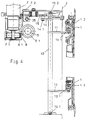
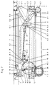
- Embodiment of the pivoting sliding door described explains which are in the generation and control the movement of the door pipe 10 from the embodiment differs according to FIGS. 1 to 6.
- This embodiment corresponds to the features Swivel sliding door according to FIGS. 1 to 5 or 1 to 4 and 6.
- the features described with these figures are not explained again below and the parts of the embodiment according to FIG. 1 up to 4 corresponding parts have the same reference numerals as designated there.
- the drive device is an electric motor 7 with a coaxial to the output shaft 7.1
- the gear 15 is with the pivot lever 12 on the door boom tube 10 does not have a rigid coupling rod, but via a two-part Coupling element from parts 18 and 19 connected.
- a leg spring 18.1 is arranged so that in the closed shown in Fig. 7 Position of the door in both parts 18 and 19 stretched position to each other and in this Position are fixed.
- a locking element snaps into place 19.2 at the connection point between the part 19 and the gear 15 in a locking device 20 a, which is a substantially T-shaped Has locking part, with a longitudinal bar 20.1 and a crossbar 20.2.
- the crossbar 20.2 can be pivoted about a vertical axis of rotation 20.3, with a clockwise rotation the Force counteracts a compression spring 21, the Holds the crossbeam to a stop 20.5.
- a locking surface is located at the end of the longitudinal beam 20.1 20.4, against which the locking element 19.2 rests.
- Trigger rod 22 connected in a fixed on Door frame 2 arranged guide 23 runs and starts has a hook 22.1 at its free end.
- a pull on the trigger rod 22 is exerted the crossbeam 20.2 against the action of the spring 21 granted a slight clockwise movement and thereby the locking element 19.2 again released so that due to the reaction moment of Drive motor 7 via the gears 7.2 and 15 of the Part 19 of the coupling element back into that in FIG. 7 position shown can be traced.
- Embodiments as a drive device Electric motor is described. It goes without saying it is also possible to use other drive devices, for example a pneumatic actuator. It is also possible for a door with two Door leaves a central drive for the two door leaves to provide.
Claims (13)
- Porte coulissante et pivotante pour véhicule pour le transport de personnes, notamment pour véhicule se déplaçant sur des rails, comprenant au moins un vantail de porte (1) oui est relié par l'intermédiaire d'un bras pivotant (3) a un organe de support (4) déplaçable horizontalement dans la direction longitudinale du véhicule sur un élément de guidage (5) fixé dans le cadre de porte, le bras pivotant (3) étant articulé à la fois au vantail de porte (1) et à l'organe de support (4), par l'intermédiaire d'axes de rotation verticaux (3.1-3.2) et le mouvement de pivotement du bras pivotant (3) étant déterminé au cours du mouvement longitudinal de l'organe de support (4) par un levier de guidage (3.3) guidé dans un rail de guidage (6) et relié rigidement au bras pivotant, caractérisé en ce que, pour la production d'un mouvement de rotation du vantail de porte (1) autour de l'axe de rotation vertical (3.1) disposé au vantail de porte, du bras pivotant (3), au début du mouvement d'ouverture, est disposé entre le vantail de porte (1) et l'organe de support (4) une liaison de guide a deux organes (9.1-9.2) et en ce que la partie (9.1) de la liaison de guide, qui est articulée a l'organe de support (4), est amenée à pivoter au cours d'une partie du mouvement longitudinal de l'organe de support (4), de façon forcée, et ainsi le point de jonction (9.4) entre les deux organes de la liaison de guide est déplacé par rapport a l'axe de rotation (3.2) disposé a l'organe de support (4), du bras pivotant (3.
- Porte coulissante et pivotante selon la revendication 1, caractérisée en ce que la partie (9.1) articulée à l'organe de support (4) de la liaison de guide est pourvue d'un rouleau de guidage (9.7) qui se déplace dans un second rail de guidage (16) fixé au cadre de porte (2) et dont la configuration détermine le pivotement de cette partie.
- Porte coulissante et pivotante selon la revendication 1, caractérisée en ce que la partie (9.1') articulée à l'organe de support (4) de la liaison de guide est pourvue d'au moins un rouleau de guidage (9.7', 9.8'), qui se déplace sur un disque à came relié de façon fixe au bras de pivotement (3) et par la configuration duquel est déterminé le pivotement de cette partie.
- Porte coulissante et pivotante selon la revendication 3, caractérisée en ce qu'à la partie (9.1') articulée à l'organe de support (4) de la liaison de guide sont disposés deux rouleaux de guidage (9.7', 9.8'), de telle façon qu'ils entourent par une liaison forcée le disque à came (17).
- Porte coulissante et pivotante selon les revendications 1 à 4, caractérisée en ce que la liaison de guide (9.1-9.2) est configurée de telle façon et sa partie (9.1) articulée à l'organe de support (4) est susceptible de pivoter de telle façon que le point de connexion (9.4) de la liaison des guides, dans la position de pivotement complète du vantail de porte, repose essentiellement sur la ligne de liaison des points d'articulation (9.3-9.5) de la liaison de guide.
- Porte coulissante et pivotante selon les revendications 1 à 5, caractérisée en ce que la liaison de guide (9.1-9.2) est configurée de telle façon et sa partie (9.1) articulée à l'organe de support (4) peut être amenée à pivoter de telle façon que la partie (9.2) articulée au vantail de porte (1), de la liaison de guide s'étende, à l'état de pivotement total vers l'intérieur et de pivotement total vers l'extérieur du vantail de porte (1), parallèlement au bras pivotant (3).
- Porte coulissante et pivotante selon les revendications 1 à 6, caractérisée en ce que le vantail de porte (1) est guidé, à son extrémité inférieure, par un autre rouleau de guidage (13.1), dans un autre rail de guidage (1.3).
- Porte coulissante et pivotante selon les revendications 1 à 7, caractérisée par un tube d'arbre de porte (10) monté pivotant autour d'un axe vertical et auquel sont disposés deux leviers à rouleau (11, 13) qui s'engagent respectivement dans des rails de guidage supérieur et inférieur (1.2, 1.3) disposés sur le vantail de porte (1).
- Porte coulissante et pivotante selon la revendication 8, caractérisée par un dispositif d'entraínement (7) dont la force d'entraínement attaque l'organe de support (4) dans la direction de l'élément de guidage (5), tandis que la force de réaction du dispositif d'entraínement exerce sur le tube d'arbre de porte (10) par l'intermédiaire d'un dispositif de transmission (7.2, 15, 14, 12) un couple qui est actif seulement au début du mouvement d'ouverture et/ou à la fin du mouvement de fermeture.
- Porte coulissante et pivotante selon la revendication 9, caractérisée en ce que le dispositif de transmission est une commande à bielle (15-14-12).
- Dispositif coulissant et pivotant selon la revendication 10, caractérisé en ce que le dispositif d'entraínement comprend un moteur électrique (7) avec un carter monté rotatif autour d'un axe de rotation disposé coaxialement à l'arbre d'entraínement (7.1) et qui est relié à un levier pivotant (12) disposé sur le tube d'arbre de porte (10), par l'intermédiaire d'un engrenage à roues dentées (7.2-15) et une tige de connexion (14).
- Porte coulissante et pivotante selon la revendication 11, caractérisée en ce que, dans la position finale du tube d'arbre de porte (10) correspondant à l'état de pivotement vers l'intérieur du vantail de porte (1), le mouvement de rotation du tube d'arbre de porte est bloqué par application de la tige de connexion (14) entre l'engrenage à roues dentées (15, 7.2) et le tube d'arbre de porte (10) à une butée (25), immédiatement en arrière de la position de point mort.
- Porte coulissante et pivotante selon la revendication 10, caractérisée en ce que le dispositif d'entraínement comporte un moteur électrique (7) avec un boítier monté rotatif autour de l'axe de rotation s'étendant coaxialement à l'arbre d'entraínement (7.1) et qui est relié à un levier pivotant (12) disposé au tube d'arbre de porte (1), par l'intermédiaire d'un engrenage à roues dentées (7.2), 15), et un élément de connexion à deux organes (18, 19), dans la position finale du tube d'arbre de porte (10), correspondant à l'état de pivotement total vers l'extérieur du vantail de porte (1), l'engrenage à roues dentées (7.2-15) étant bloqué par un dispositif de verrouillage (20) qui est libéré seulement immédiatement avant l'atteinte de la position finale de fermeture de l'organe de support (4) et, dans la position finale du tube d'arbre de porte (10), correspondant à l'état de pivotement total vers l'intérieur du vantail de porte (1), le mouvement de rotation du tube d'arbre de porte étant bloqué par application des organes étendus (18, 19) de l'élément de connexion entre l'engrenage à roues dentées (7.2, 15) et le tube d'arbre de porte, à une butée (26) immédiatement en arrière d'une position de point mort (10).
Applications Claiming Priority (2)
| Application Number | Priority Date | Filing Date | Title |
|---|---|---|---|
| DE4444041A DE4444041C2 (de) | 1994-12-10 | 1994-12-10 | Schwenkschiebetür für Fahrzeuge zur Personenbeförderung |
| DE4444041 | 1994-12-10 |
Publications (2)
| Publication Number | Publication Date |
|---|---|
| EP0716004A1 EP0716004A1 (fr) | 1996-06-12 |
| EP0716004B1 true EP0716004B1 (fr) | 1999-01-07 |
Family
ID=6535480
Family Applications (1)
| Application Number | Title | Priority Date | Filing Date |
|---|---|---|---|
| EP95119189A Expired - Lifetime EP0716004B1 (fr) | 1994-12-10 | 1995-12-06 | Porte pivotante et coulissante pour véhicules de transport de personnes |
Country Status (4)
| Country | Link |
|---|---|
| EP (1) | EP0716004B1 (fr) |
| AT (1) | ATE175389T1 (fr) |
| DE (2) | DE4444041C2 (fr) |
| ES (1) | ES2127459T3 (fr) |
Families Citing this family (15)
| Publication number | Priority date | Publication date | Assignee | Title |
|---|---|---|---|---|
| AT405155B (de) * | 1997-04-28 | 1999-06-25 | Ife Gmbh | Schwenkschiebetür für fahrzeuge |
| DE19723837A1 (de) * | 1997-06-06 | 1998-12-10 | Volkswagen Ag | Rollenführung für eine Schiebetür, insbesondere für Kraftfahrzeuge |
| DE19735181C2 (de) * | 1997-08-14 | 2001-11-15 | Webasto Tuersysteme Gmbh | Schwenkschiebetür für Fahrzeuge |
| FR2779996B1 (fr) * | 1998-06-19 | 2000-07-21 | Renault | Dispositif de guidage pour porte coulissante de vehicules automobiles |
| ES2163967B2 (es) * | 1999-03-08 | 2003-06-01 | Faiveley Espanola | Sistema de apertura/cierre para puertas correderas encajables. |
| DE502005006218D1 (de) * | 2005-09-23 | 2009-01-22 | Fahrzeugtechnik Dessau Ag Rail | Einrichtung zur Bewegung des Türblattes einer Schwenkschiebetür, insbesondere für Schienenfahrzeuge |
| DE102007035231A1 (de) * | 2007-06-28 | 2009-02-05 | Dura Automotive Body & Glass Systems Gmbh | Schiebetüre für ein Fahrzeug |
| EP2008846B1 (fr) * | 2007-06-28 | 2010-07-07 | DURA Automotive Body and Glass Systems GmbH | Porte coulissante pour véhicule |
| DE102010027136A1 (de) * | 2010-07-14 | 2012-01-19 | Knorr-Bremse Gmbh | Vorrichtung zum Durchführen einer Öffnungsbewegung einer Tür |
| AT514884B1 (de) * | 2013-09-23 | 2016-01-15 | Knorr Bremse Ges Mit Beschränkter Haftung | Schwenkschiebetürmodul mit dynamisch sicherer Übertotpunktverriegelung |
| DE102013111890A1 (de) * | 2013-09-23 | 2015-03-26 | Knorr-Bremse Gmbh | Schwenkschiebetürmodul für ein Schienenfahrzeug mit mehreren über einen Bowdenzug gekoppelten Übertotpunktverriegelungen |
| GB2532176B (en) * | 2014-05-20 | 2020-12-30 | Sg Technical Systems Ltd | Access doors |
| DE102016100212B4 (de) * | 2016-01-06 | 2017-08-24 | Bombardier Transportation Gmbh | Türvorrichtung und Verfahren zum Betrieb einer Türvorrichtung |
| GB2548318A (en) * | 2016-01-12 | 2017-09-20 | S G Technical Systems Ltd | Access Doors |
| CN106740925B (zh) * | 2016-12-29 | 2019-04-30 | 中车唐山机车车辆有限公司 | 一种用于货运动车组的塞拉门系统 |
Family Cites Families (5)
| Publication number | Priority date | Publication date | Assignee | Title |
|---|---|---|---|---|
| NL282836A (fr) * | 1961-09-12 | 1900-01-01 | ||
| DE3231181A1 (de) * | 1982-08-21 | 1984-02-23 | Gebr. Bode & Co, 3500 Kassel | Aufhaengevorrichtung fuer den tuerfluegel einer ausschwenkbaren schiebetuer fuer fahrzeuge, insbes. schienenfahrzeuge |
| DE3742279A1 (de) * | 1987-12-12 | 1989-07-06 | Bode & Co Geb | Schwenkschiebetuer fuer fahrzeuge |
| FR2658773B1 (fr) * | 1990-02-23 | 1992-06-12 | Faiveley Transport | Porte a vantail coulissant, en particulier pour vehicule ferroviaire. |
| DE4316253A1 (de) * | 1993-05-14 | 1994-11-17 | Bode & Co Geb | Vorrichtung zur Bewegung einer Schwenkschiebetür für Fahrzeuge zur Personenbeförderung, insbesondere Schienenfahrzeuge |
-
1994
- 1994-12-10 DE DE4444041A patent/DE4444041C2/de not_active Expired - Fee Related
-
1995
- 1995-12-06 ES ES95119189T patent/ES2127459T3/es not_active Expired - Lifetime
- 1995-12-06 DE DE59504734T patent/DE59504734D1/de not_active Expired - Lifetime
- 1995-12-06 AT AT95119189T patent/ATE175389T1/de active
- 1995-12-06 EP EP95119189A patent/EP0716004B1/fr not_active Expired - Lifetime
Also Published As
| Publication number | Publication date |
|---|---|
| DE4444041C2 (de) | 1996-09-26 |
| ES2127459T3 (es) | 1999-04-16 |
| EP0716004A1 (fr) | 1996-06-12 |
| DE59504734D1 (de) | 1999-02-18 |
| ATE175389T1 (de) | 1999-01-15 |
| DE4444041A1 (de) | 1996-06-13 |
Similar Documents
| Publication | Publication Date | Title |
|---|---|---|
| EP0536528B1 (fr) | Dispositif de manoeuvre d'une porte pivotante-coulissante pour véhicules de transport en commun, notamment ferroviaires | |
| EP0320591B1 (fr) | Porte pivotante coulissante pour véhicules | |
| EP0716004B1 (fr) | Porte pivotante et coulissante pour véhicules de transport de personnes | |
| EP0395847B1 (fr) | Assemblage d'entraînement pour un toit pliant entraîné par moteur | |
| DE2942006C2 (de) | Schiebedach für Kraftfahrzeuge | |
| EP1767388B1 (fr) | Porte pivotante-coulissante pour véhicules de transport de personnes | |
| DE102005034346A1 (de) | Schiebetüre für ein Kraftfahrzeug | |
| DE102009011858A1 (de) | Schiebetür mit verlängertem Verfahrweg und mit gelenkig angebrachtem Rollenbügel | |
| DE4316253A1 (de) | Vorrichtung zur Bewegung einer Schwenkschiebetür für Fahrzeuge zur Personenbeförderung, insbesondere Schienenfahrzeuge | |
| DE2139086A1 (de) | Fensterheber für vertikal unterteilte Türfenster von Kraftfahrzeugen | |
| DE202005007984U1 (de) | Schiebetür oder Schwenkschiebetür für Fahrzeuge des öffentlichen Personennah- und -fernverkehrs | |
| DE2507893B2 (de) | Fensterheber für vertikal unterteilte Kraftfahrzeugschiebefenster | |
| DE4331078A1 (de) | Vorrichtung zur Bewegung einer Schwenkschiebetür für Fahrzeuge zur Personenbeförderung, insbesondere Schienenfahrzeuge | |
| EP0794310B1 (fr) | Porte à vanteaux pliables | |
| DE3400753A1 (de) | Aussenschwingtuer fuer fahrzeuge und ihre betaetigungsvorrichtung | |
| DE10105771B4 (de) | Verschlußvorrichtung für ein Cabriolet-Verdeck | |
| DE2405881A1 (de) | Fensterheber fuer vertikal unterteilte tuerfenster von kraftfahrzeugen | |
| DE102007035230A1 (de) | Schiebetüre für ein Fahrzeug | |
| DE10229808A1 (de) | Verdeck für ein Cabriolet-Fahrzeug | |
| DE1814224B2 (de) | Mehrflügeliges Drehfalttor | |
| DE19624706B4 (de) | Schwenkschiebetür für ein Fahrzeug | |
| DE102005061978B3 (de) | Scharniervorrichtung | |
| DE2759372A1 (de) | Fahrzeugschwingtuer | |
| DE10018732A1 (de) | Auswerfervorrichtung für eine Klappenanordnung, insbesondere eine Kraftfahrzeug-Heckklappenanordnung | |
| DE4311339C1 (de) | Vorrichtung zur Herstellung einer kraftflußübertragenden Verbindung zwischen Fahrzeugtür und Fahrzeugkarosserie eines Kraftfahrzeugs |
Legal Events
| Date | Code | Title | Description |
|---|---|---|---|
| PUAI | Public reference made under article 153(3) epc to a published international application that has entered the european phase |
Free format text: ORIGINAL CODE: 0009012 |
|
| AK | Designated contracting states |
Kind code of ref document: A1 Designated state(s): AT BE CH DE ES FR GB IT LI LU NL |
|
| 17P | Request for examination filed |
Effective date: 19961204 |
|
| GRAG | Despatch of communication of intention to grant |
Free format text: ORIGINAL CODE: EPIDOS AGRA |
|
| 17Q | First examination report despatched |
Effective date: 19980317 |
|
| GRAG | Despatch of communication of intention to grant |
Free format text: ORIGINAL CODE: EPIDOS AGRA |
|
| GRAH | Despatch of communication of intention to grant a patent |
Free format text: ORIGINAL CODE: EPIDOS IGRA |
|
| GRAH | Despatch of communication of intention to grant a patent |
Free format text: ORIGINAL CODE: EPIDOS IGRA |
|
| GRAA | (expected) grant |
Free format text: ORIGINAL CODE: 0009210 |
|
| AK | Designated contracting states |
Kind code of ref document: B1 Designated state(s): AT BE CH DE ES FR GB IT LI LU NL |
|
| PG25 | Lapsed in a contracting state [announced via postgrant information from national office to epo] |
Ref country code: NL Free format text: LAPSE BECAUSE OF FAILURE TO SUBMIT A TRANSLATION OF THE DESCRIPTION OR TO PAY THE FEE WITHIN THE PRESCRIBED TIME-LIMIT Effective date: 19990107 Ref country code: GB Free format text: LAPSE BECAUSE OF NON-PAYMENT OF DUE FEES Effective date: 19990107 Ref country code: FR Free format text: LAPSE BECAUSE OF FAILURE TO SUBMIT A TRANSLATION OF THE DESCRIPTION OR TO PAY THE FEE WITHIN THE PRESCRIBED TIME-LIMIT Effective date: 19990107 |
|
| REF | Corresponds to: |
Ref document number: 175389 Country of ref document: AT Date of ref document: 19990115 Kind code of ref document: T |
|
| ITF | It: translation for a ep patent filed |
Owner name: STUDIO INGG. FISCHETTI & WEBER |
|
| REG | Reference to a national code |
Ref country code: CH Ref legal event code: NV Representative=s name: A. BRAUN, BRAUN, HERITIER, ESCHMANN AG PATENTANWAE Ref country code: CH Ref legal event code: EP |
|
| REF | Corresponds to: |
Ref document number: 59504734 Country of ref document: DE Date of ref document: 19990218 |
|
| REG | Reference to a national code |
Ref country code: ES Ref legal event code: FG2A Ref document number: 2127459 Country of ref document: ES Kind code of ref document: T3 |
|
| NLV1 | Nl: lapsed or annulled due to failure to fulfill the requirements of art. 29p and 29m of the patents act | ||
| EN | Fr: translation not filed | ||
| GBV | Gb: ep patent (uk) treated as always having been void in accordance with gb section 77(7)/1977 [no translation filed] |
Effective date: 19990107 |
|
| PLBE | No opposition filed within time limit |
Free format text: ORIGINAL CODE: 0009261 |
|
| STAA | Information on the status of an ep patent application or granted ep patent |
Free format text: STATUS: NO OPPOSITION FILED WITHIN TIME LIMIT |
|
| PGFP | Annual fee paid to national office [announced via postgrant information from national office to epo] |
Ref country code: ES Payment date: 19991203 Year of fee payment: 5 |
|
| PG25 | Lapsed in a contracting state [announced via postgrant information from national office to epo] |
Ref country code: LU Free format text: LAPSE BECAUSE OF NON-PAYMENT OF DUE FEES Effective date: 19991206 |
|
| 26N | No opposition filed | ||
| PG25 | Lapsed in a contracting state [announced via postgrant information from national office to epo] |
Ref country code: LI Free format text: LAPSE BECAUSE OF NON-PAYMENT OF DUE FEES Effective date: 19991231 Ref country code: CH Free format text: LAPSE BECAUSE OF NON-PAYMENT OF DUE FEES Effective date: 19991231 Ref country code: BE Free format text: LAPSE BECAUSE OF NON-PAYMENT OF DUE FEES Effective date: 19991231 |
|
| BERE | Be: lapsed |
Owner name: GEBRUDER BODE & CO. G.M.B.H. Effective date: 19991231 |
|
| PG25 | Lapsed in a contracting state [announced via postgrant information from national office to epo] |
Ref country code: ES Free format text: LAPSE BECAUSE OF NON-PAYMENT OF DUE FEES Effective date: 20011207 |
|
| REG | Reference to a national code |
Ref country code: ES Ref legal event code: FD2A Effective date: 20020112 |
|
| PGFP | Annual fee paid to national office [announced via postgrant information from national office to epo] |
Ref country code: DE Payment date: 20141218 Year of fee payment: 20 |
|
| PGFP | Annual fee paid to national office [announced via postgrant information from national office to epo] |
Ref country code: AT Payment date: 20141215 Year of fee payment: 20 |
|
| PGFP | Annual fee paid to national office [announced via postgrant information from national office to epo] |
Ref country code: IT Payment date: 20141218 Year of fee payment: 20 |
|
| REG | Reference to a national code |
Ref country code: DE Ref legal event code: R071 Ref document number: 59504734 Country of ref document: DE |
|
| REG | Reference to a national code |
Ref country code: AT Ref legal event code: MK07 Ref document number: 175389 Country of ref document: AT Kind code of ref document: T Effective date: 20151206 |