EP0715118B1 - Einrichtung zur Rückführung von verbrauchten Schmierstoffen - Google Patents
Einrichtung zur Rückführung von verbrauchten Schmierstoffen Download PDFInfo
- Publication number
- EP0715118B1 EP0715118B1 EP95114010A EP95114010A EP0715118B1 EP 0715118 B1 EP0715118 B1 EP 0715118B1 EP 95114010 A EP95114010 A EP 95114010A EP 95114010 A EP95114010 A EP 95114010A EP 0715118 B1 EP0715118 B1 EP 0715118B1
- Authority
- EP
- European Patent Office
- Prior art keywords
- lubricant
- pump
- piston
- consumer
- collection point
- Prior art date
- Legal status (The legal status is an assumption and is not a legal conclusion. Google has not performed a legal analysis and makes no representation as to the accuracy of the status listed.)
- Expired - Lifetime
Links
- 239000000314 lubricant Substances 0.000 title claims abstract description 37
- 230000001105 regulatory effect Effects 0.000 claims description 5
- 230000000694 effects Effects 0.000 claims description 3
- 238000005461 lubrication Methods 0.000 abstract description 12
- 239000004519 grease Substances 0.000 abstract description 10
- 238000005086 pumping Methods 0.000 abstract 2
- 230000000750 progressive effect Effects 0.000 description 4
- 239000010687 lubricating oil Substances 0.000 description 2
- 238000004064 recycling Methods 0.000 description 2
- 230000007613 environmental effect Effects 0.000 description 1
- 238000010438 heat treatment Methods 0.000 description 1
- 239000003595 mist Substances 0.000 description 1
- 239000003921 oil Substances 0.000 description 1
Images
Classifications
-
- F—MECHANICAL ENGINEERING; LIGHTING; HEATING; WEAPONS; BLASTING
- F16—ENGINEERING ELEMENTS AND UNITS; GENERAL MEASURES FOR PRODUCING AND MAINTAINING EFFECTIVE FUNCTIONING OF MACHINES OR INSTALLATIONS; THERMAL INSULATION IN GENERAL
- F16N—LUBRICATING
- F16N7/00—Arrangements for supplying oil or unspecified lubricant from a stationary reservoir or the equivalent in or on the machine or member to be lubricated
- F16N7/38—Arrangements for supplying oil or unspecified lubricant from a stationary reservoir or the equivalent in or on the machine or member to be lubricated with a separate pump; Central lubrication systems
- F16N7/385—Central lubrication systems
-
- F—MECHANICAL ENGINEERING; LIGHTING; HEATING; WEAPONS; BLASTING
- F16—ENGINEERING ELEMENTS AND UNITS; GENERAL MEASURES FOR PRODUCING AND MAINTAINING EFFECTIVE FUNCTIONING OF MACHINES OR INSTALLATIONS; THERMAL INSULATION IN GENERAL
- F16N—LUBRICATING
- F16N13/00—Lubricating-pumps
- F16N13/02—Lubricating-pumps with reciprocating piston
- F16N13/06—Actuation of lubricating-pumps
- F16N13/16—Actuation of lubricating-pumps with fluid drive
Definitions
- the invention relates to a device for recycling of consumed lubricants by consumers, especially used greases from e.g. from a lubricant supply system, such as a central lubrication system, supplied warehouses, to a collection point, e.g. B. one Collection container, via a return line from one Lubricant outlet of the respective consumer to the Collection point of the lubricant supply system.
- a lubricant supply system such as a central lubrication system, supplied warehouses
- a collection point e.g. B. one Collection container
- EP-A-0 614 038 describes a device for recycling consumed by an oil mist generator to consumers supplied lubricating oil is known, in which the lubricating oil over a return line flows into a container from which from it with the help of a hand pump a return line can be supplied.
- This lubricant system is suitable not for processing high-viscosity lubricants, like greases.
- the object of the present invention is to overcome this disadvantage remedy simple and reliable.
- the invention further suggested that the consumer, apart from its lubricant inlet and the lubricant outlet, against Lubricant passage is sealed.
- check valves are provided before and after the pump element provided in the return line.
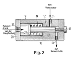
- the pump element preferably consists of a pump body with one that is axially movable in a pump chamber Piston that excess lubricant when moving backwards of the piston from the lubricant outlet of the consumer sucked a pump inlet into the pump chamber and at forward movement of the piston via a pump outlet in the return line pushed out towards the collection point becomes.
- This can e.g. B. in cooperation with each one before and after the pump element in the return line arranged check valve can be ensured.
- the piston is particularly advantageous, preferably against the Effect of a return spring, from the pump pressure from the Main line of the lubricant supply system, preferably the central lubrication system itself. Whenever the pressure in the main line drops, the piston moves automatically in the opposite direction using the return spring.
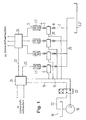
- a Return line 3 connected.
- a pump element 6 for. B. a pump element 2, turned on.
- Die individual return lines 3 are to a manifold 26 summarized, which opens into a collecting container 2 '.
- Used grease does not get into the bearings 1 ' the environment but is used exclusively by the return lines 3 taken over. With the help of the return lines 3 switched on and from the main line 15 from automatically operated pump elements 6 will interact with the two check valves 7 and 8 that used up Grease via the return lines 3 to the Manifold 26 and from there into the collecting container 2 ' promoted. This makes a significant contribution to environmental relief accomplished.
Landscapes
- Engineering & Computer Science (AREA)
- General Engineering & Computer Science (AREA)
- Mechanical Engineering (AREA)
- Details Of Reciprocating Pumps (AREA)
- Rolling Contact Bearings (AREA)
- Lubricants (AREA)
- Reciprocating Pumps (AREA)
- Lubrication Of Internal Combustion Engines (AREA)
Description
- Fig. 1
- die schematische Darstellung einer die Erfindung aufweisenden Zentralschmieranlage mit Fettrückführung und
- Fig. 2
- ein Pumpenelement schematisch im Schnitt.
- 1
- Verbraucher
- 1'
- Lager
- 2
- Sammelstelle
- 2'
- Sammelbehälter
- 3
- Rückführungsleitung
- 4
- Schmierstoffauslaß des Verbrauchers
- 5
- Schmierstoffeinlaß des Verbrauchers
- 6
- Pumpenelement
- 7
- Rückschlagventil
- 8
- Rückschlagventil
- 9
- Pumpenkörper
- 10
- Kolben
- 11
- Pumpeneinlaß
- 12
- Pumpenkammer
- 13
- Pumpenauslaß
- 14
- Rückstellfeder
- 15
- Hauptleitung A
- 16
- Hauptleitung B
- 17
- Regulierschraube
- 18
- Vorratsbehälter
- 19
- Schmierpumpe
- 20
- Umsteuerung
- 21
- Zweileitungsverteiler
- 22
- Leitungsabschnitt
- 23
- Leitung
- 24
- Progressivverteiler
- 25
- weitere Leitungen
- 26
- Sammelleitung
- 27
- Kopfabschnitt
- 28
- Stirnwandung
- 29
- Fetteinlaß
- 30
- Schulter
- 31
- Fetteinlaß
Claims (6)
- Einrichtung zur Rückführung von verbrauchten Schmier stoffen von Verbrauchern (1) zu einer Sammelstelle (2) über eine Rückführungsleitung (3) von einem Schmierstoffauslaß (4) des jeweiligen Verbrauchers (1) zu der Sammelstelle (2) einer Schmierstoffversorgunganlage, dadurch gekennzeichnet, daß dem Verbraucher (1) in der Rückführungsleitung (3) ein Pumpenelement (6) derart unmittelbar nachgeordnet ist, daß bei Betätigung des Pumpenelements (6) Überschußschmierstoff über einen Pumpeneinlaß (11) von dem Verbraucher (1) abgesaugt und anschließend über einen Pumpenauslaß (13) in die Rückführungsleitung (3) in Richtung der Sammelstelle (2) herausgedrückt wird.
- Einrichtung nach Anspruch 1, dadurch gekennzeichnet, daß der Verbraucher (1), abgesehen von seinem Schmierstoffeinlaß (5) und dem Schmierstoffauslaß (4), gegen Schmierstoffdurchtritt abgedichtet ist.
- Einrichtung nach Anspruch 1 oder 2, dadurch gekennzeichnet, daß vor und nach dem Pumpenelement (6) Rückschlagventile (7, 8) in der Rückführungsleitung (3) vorgesehen sind.
- Einrichtung nach einem der Ansprüche 1 bis 3, dadurch gekennzeichnet, daß das Pumpenelement (6) einen Pumpenkörper (9) mit einem in einer Pumpenkammer (12) derart axial beweglichen Kolben (10) aufweist, daß Überschußschmierstoff bei einer Rückwärtsbewegung des Kolbens (10) von dem Schmierstoffauslaß (4) des Verbrauchers (1) in die Pumpenkammer (12) eingesaugt und bei einer Vorwärtsbewegung des Kolbens (10) in die Rückführungsleitung (3) herausgedrückt wird.
- Einrichtung nach Anspruch 4, dadurch gekennzeichnet, daß der Kolben (10), vorzugsweise gegen die Wirkung einer Rückstellfeder (14), pneumatisch oder hydraulisch, von dem Pumpendruck aus der Hauptleitung (15) der Schmierstoffversorgungsanlage antreibbar ist.
- Einrichtung nach Anspruch 4 oder 5, dadurch gekennzeichnet, daß der Förderhub des Kolbens (10) mittels als Anschlag wirkender Regulierschraube (17) einstellbar ist.
Applications Claiming Priority (2)
| Application Number | Priority Date | Filing Date | Title |
|---|---|---|---|
| DE4442188 | 1994-11-28 | ||
| DE4442188A DE4442188C1 (de) | 1994-11-28 | 1994-11-28 | Einrichtung zur Rückführung von verbrauchten Schmierstoffen sowie Pumpenelement hierfür |
Publications (2)
| Publication Number | Publication Date |
|---|---|
| EP0715118A1 EP0715118A1 (de) | 1996-06-05 |
| EP0715118B1 true EP0715118B1 (de) | 1999-12-08 |
Family
ID=6534265
Family Applications (1)
| Application Number | Title | Priority Date | Filing Date |
|---|---|---|---|
| EP95114010A Expired - Lifetime EP0715118B1 (de) | 1994-11-28 | 1995-09-07 | Einrichtung zur Rückführung von verbrauchten Schmierstoffen |
Country Status (3)
| Country | Link |
|---|---|
| EP (1) | EP0715118B1 (de) |
| AT (1) | ATE187534T1 (de) |
| DE (2) | DE4442188C1 (de) |
Cited By (1)
| Publication number | Priority date | Publication date | Assignee | Title |
|---|---|---|---|---|
| WO2015180638A1 (zh) * | 2014-05-27 | 2015-12-03 | 郑州奥特科技有限公司 | 一种双路控制吸脂器及废脂回收装置 |
Families Citing this family (9)
| Publication number | Priority date | Publication date | Assignee | Title |
|---|---|---|---|---|
| DE19900560A1 (de) * | 1999-01-09 | 2000-07-13 | Sms Demag Ag | Schmierölumlaufsystem |
| GB0218849D0 (en) | 2002-08-14 | 2002-09-25 | Rolls Royce Plc | Lubrication system for gas turbine engine |
| DE102010061916B4 (de) | 2010-11-25 | 2013-03-28 | Aktiebolaget Skf | Pumpe zum Fördern eines Mediums und Schmiermittelsystem |
| EP2554892A1 (de) | 2011-08-03 | 2013-02-06 | Delimon GmbH | Druckmittelwandler |
| DE102011088228B3 (de) * | 2011-12-12 | 2013-03-28 | Aktiebolaget Skf | Schmiermittelsystem und Windkraftanlage |
| CN104520631B (zh) | 2012-08-01 | 2017-10-20 | 维斯塔斯风力系统有限公司 | 对要经由消耗方润滑剂被监测的消耗方进行润滑的方法和系统 |
| CN109404708A (zh) * | 2018-12-19 | 2019-03-01 | 国电联合动力技术有限公司 | 用于潮流能机组的智能轴承润滑系统及其机组、控制方法 |
| CN112762335A (zh) * | 2021-01-18 | 2021-05-07 | 江苏美森洗涤设备有限公司 | 用于洗脱机的轴承润滑机构及洗脱机 |
| GB2618360A (en) * | 2022-05-05 | 2023-11-08 | Caterpillar Sarl | Valve for supplying and purging lubricants from systems |
Citations (1)
| Publication number | Priority date | Publication date | Assignee | Title |
|---|---|---|---|---|
| EP0614038A1 (de) * | 1993-01-29 | 1994-09-07 | Lubrication Systems Company Of Texas, Inc. | Schmierungsanlage |
Family Cites Families (5)
| Publication number | Priority date | Publication date | Assignee | Title |
|---|---|---|---|---|
| DE710595C (de) * | 1937-02-18 | 1941-09-17 | Rheinmetall Borsig Akt Ges | Gleitlager, insbesondere fuer schnell umlaufende Wellen, mit einer am Wellenaustritt vorgesehenen Abdichteinrichtung |
| US2260497A (en) * | 1939-08-09 | 1941-10-28 | Stewart Warner Corp | Lubricating system and apparatus |
| DE3430040A1 (de) * | 1984-08-16 | 1986-02-20 | De Limon Fluhme GmbH & Co, 4000 Düsseldorf | Zentralschmieranlage fuer wandernde schmierstellen |
| US5285871A (en) * | 1992-08-17 | 1994-02-15 | Mechanical Tool & Engineering Co. | System for distributing viscous lubricant |
| DE59204617D1 (de) * | 1992-09-22 | 1996-01-18 | Limon Fluhme & Co De | Vorrichtung zur Schmierstoffversorgung. |
-
1994
- 1994-11-28 DE DE4442188A patent/DE4442188C1/de not_active Expired - Fee Related
-
1995
- 1995-09-07 EP EP95114010A patent/EP0715118B1/de not_active Expired - Lifetime
- 1995-09-07 AT AT95114010T patent/ATE187534T1/de not_active IP Right Cessation
- 1995-09-07 DE DE59507382T patent/DE59507382D1/de not_active Expired - Fee Related
Patent Citations (1)
| Publication number | Priority date | Publication date | Assignee | Title |
|---|---|---|---|---|
| EP0614038A1 (de) * | 1993-01-29 | 1994-09-07 | Lubrication Systems Company Of Texas, Inc. | Schmierungsanlage |
Cited By (1)
| Publication number | Priority date | Publication date | Assignee | Title |
|---|---|---|---|---|
| WO2015180638A1 (zh) * | 2014-05-27 | 2015-12-03 | 郑州奥特科技有限公司 | 一种双路控制吸脂器及废脂回收装置 |
Also Published As
| Publication number | Publication date |
|---|---|
| ATE187534T1 (de) | 1999-12-15 |
| DE59507382D1 (de) | 2000-01-13 |
| DE4442188C1 (de) | 1996-08-01 |
| EP0715118A1 (de) | 1996-06-05 |
Similar Documents
| Publication | Publication Date | Title |
|---|---|---|
| DE69518106T2 (de) | Schmiersystem für ein in axialer Richtung hin- und herbewegbares Kraftwerkzeug | |
| EP3938695B1 (de) | Schmierstoffspender | |
| EP0252251B1 (de) | Hydrostatisches Stützelement | |
| DE4442188C1 (de) | Einrichtung zur Rückführung von verbrauchten Schmierstoffen sowie Pumpenelement hierfür | |
| EP2004997A1 (de) | Förderpumpe und dichtungsanordnung hierfür | |
| EP2554892A1 (de) | Druckmittelwandler | |
| DE102009019418B4 (de) | Umlaufverdrängerpumpe mit verbesserter Lagerschmierung | |
| DE102014212600A1 (de) | Integrierte Schmierpumpe | |
| DE202015100703U1 (de) | Schmiermittelspenderkopf, Schmiermittelspender und Applikationselement | |
| EP1967786A1 (de) | Dosiervorrichtung für einen Schmierstoffspender | |
| DE9308066U1 (de) | Kolbenpumpe | |
| DE69428550T2 (de) | Fluidumdosieranlage | |
| EP2927500B1 (de) | Verfahren und system zur versorgung einer lageranordnung | |
| DE1600352B2 (de) | Schmiersystem für eine Kraftmaschine | |
| DE19524048C2 (de) | Pumpe zur Förderung nicht fließfähiger Medien | |
| DE1906977A1 (de) | Hydraulikpumpe mit pneumatischem Antrieb | |
| DE19506320C1 (de) | Kalander | |
| DE2526859C3 (de) | Schmiervorrichtung mit Vorratsbehälter | |
| DE69816140T2 (de) | Einfach wirkende, handbetätigte Pumpe für eine Schmierungsanlage mit verformbarem Ventil | |
| DE3027288C2 (de) | Axialkolbenpumpe | |
| DE2304910A1 (de) | Vorrichtung zum zerstaeuben von oel in einer druckluftleitung | |
| DE3405690A1 (de) | Progressivverteiler | |
| DE1958079A1 (de) | Hochdruckfoerderpumpe fuer viskose Medien | |
| DE940742C (de) | Geraet fuer die Strahlumlaufschmierung von Waelzlagern | |
| DE3500432A1 (de) | Schnellaufende hochdruck-wasser-radialkolbenpumpe, insbesondere fuer den untertagebetrieb |
Legal Events
| Date | Code | Title | Description |
|---|---|---|---|
| PUAI | Public reference made under article 153(3) epc to a published international application that has entered the european phase |
Free format text: ORIGINAL CODE: 0009012 |
|
| AK | Designated contracting states |
Kind code of ref document: A1 Designated state(s): AT BE CH DE DK ES FR GB GR IE IT LI NL PT SE |
|
| RBV | Designated contracting states (corrected) |
Designated state(s): AT BE CH DE DK ES FR GB GR IE IT LI NL PT SE |
|
| 17P | Request for examination filed |
Effective date: 19960622 |
|
| ITCL | It: translation for ep claims filed |
Representative=s name: BUGNION S.P.A. |
|
| 17Q | First examination report despatched |
Effective date: 19971023 |
|
| GRAG | Despatch of communication of intention to grant |
Free format text: ORIGINAL CODE: EPIDOS AGRA |
|
| GRAG | Despatch of communication of intention to grant |
Free format text: ORIGINAL CODE: EPIDOS AGRA |
|
| GRAH | Despatch of communication of intention to grant a patent |
Free format text: ORIGINAL CODE: EPIDOS IGRA |
|
| GRAH | Despatch of communication of intention to grant a patent |
Free format text: ORIGINAL CODE: EPIDOS IGRA |
|
| GRAA | (expected) grant |
Free format text: ORIGINAL CODE: 0009210 |
|
| AK | Designated contracting states |
Kind code of ref document: B1 Designated state(s): AT BE CH DE DK ES FR GB GR IE IT LI NL PT SE |
|
| PG25 | Lapsed in a contracting state [announced via postgrant information from national office to epo] |
Ref country code: SE Free format text: THE PATENT HAS BEEN ANNULLED BY A DECISION OF A NATIONAL AUTHORITY Effective date: 19991208 Ref country code: NL Free format text: LAPSE BECAUSE OF FAILURE TO SUBMIT A TRANSLATION OF THE DESCRIPTION OR TO PAY THE FEE WITHIN THE PRESCRIBED TIME-LIMIT Effective date: 19991208 Ref country code: IT Free format text: LAPSE BECAUSE OF FAILURE TO SUBMIT A TRANSLATION OF THE DESCRIPTION OR TO PAY THE FEE WITHIN THE PRE;WARNING: LAPSES OF ITALIAN PATENTS WITH EFFECTIVE DATE BEFORE 2007 MAY HAVE OCCURRED AT ANY TIME BEFORE 2007. THE CORRECT EFFECTIVE DATE MAY BE DIFFERENT FROM THE ONE RECORDED.SCRIBED TIME-LIMIT Effective date: 19991208 Ref country code: GR Free format text: LAPSE BECAUSE OF NON-PAYMENT OF DUE FEES Effective date: 19991208 Ref country code: GB Free format text: LAPSE BECAUSE OF FAILURE TO SUBMIT A TRANSLATION OF THE DESCRIPTION OR TO PAY THE FEE WITHIN THE PRESCRIBED TIME-LIMIT Effective date: 19991208 Ref country code: FR Free format text: LAPSE BECAUSE OF FAILURE TO SUBMIT A TRANSLATION OF THE DESCRIPTION OR TO PAY THE FEE WITHIN THE PRESCRIBED TIME-LIMIT Effective date: 19991208 Ref country code: ES Free format text: THE PATENT HAS BEEN ANNULLED BY A DECISION OF A NATIONAL AUTHORITY Effective date: 19991208 |
|
| REF | Corresponds to: |
Ref document number: 187534 Country of ref document: AT Date of ref document: 19991215 Kind code of ref document: T |
|
| REG | Reference to a national code |
Ref country code: CH Ref legal event code: EP |
|
| REF | Corresponds to: |
Ref document number: 59507382 Country of ref document: DE Date of ref document: 20000113 |
|
| REG | Reference to a national code |
Ref country code: IE Ref legal event code: FG4D |
|
| PG25 | Lapsed in a contracting state [announced via postgrant information from national office to epo] |
Ref country code: DK Free format text: LAPSE BECAUSE OF FAILURE TO SUBMIT A TRANSLATION OF THE DESCRIPTION OR TO PAY THE FEE WITHIN THE PRESCRIBED TIME-LIMIT Effective date: 20000308 |
|
| PG25 | Lapsed in a contracting state [announced via postgrant information from national office to epo] |
Ref country code: PT Free format text: LAPSE BECAUSE OF FAILURE TO SUBMIT A TRANSLATION OF THE DESCRIPTION OR TO PAY THE FEE WITHIN THE PRESCRIBED TIME-LIMIT Effective date: 20000309 |
|
| NLV1 | Nl: lapsed or annulled due to failure to fulfill the requirements of art. 29p and 29m of the patents act | ||
| EN | Fr: translation not filed | ||
| GBV | Gb: ep patent (uk) treated as always having been void in accordance with gb section 77(7)/1977 [no translation filed] |
Effective date: 19991208 |
|
| PG25 | Lapsed in a contracting state [announced via postgrant information from national office to epo] |
Ref country code: AT Free format text: LAPSE BECAUSE OF NON-PAYMENT OF DUE FEES Effective date: 20000907 |
|
| PG25 | Lapsed in a contracting state [announced via postgrant information from national office to epo] |
Ref country code: LI Free format text: LAPSE BECAUSE OF NON-PAYMENT OF DUE FEES Effective date: 20000930 Ref country code: CH Free format text: LAPSE BECAUSE OF NON-PAYMENT OF DUE FEES Effective date: 20000930 Ref country code: BE Free format text: LAPSE BECAUSE OF NON-PAYMENT OF DUE FEES Effective date: 20000930 |
|
| PLBE | No opposition filed within time limit |
Free format text: ORIGINAL CODE: 0009261 |
|
| STAA | Information on the status of an ep patent application or granted ep patent |
Free format text: STATUS: NO OPPOSITION FILED WITHIN TIME LIMIT |
|
| PG25 | Lapsed in a contracting state [announced via postgrant information from national office to epo] |
Ref country code: IE Free format text: LAPSE BECAUSE OF NON-PAYMENT OF DUE FEES Effective date: 20001116 |
|
| 26N | No opposition filed | ||
| REG | Reference to a national code |
Ref country code: IE Ref legal event code: FD4D |
|
| BERE | Be: lapsed |
Owner name: LINCOLN G.M.B.H. Effective date: 20000930 |
|
| REG | Reference to a national code |
Ref country code: CH Ref legal event code: PL |
|
| PG25 | Lapsed in a contracting state [announced via postgrant information from national office to epo] |
Ref country code: DE Free format text: LAPSE BECAUSE OF NON-PAYMENT OF DUE FEES Effective date: 20010601 |