EP0714331B1 - Fonctionnement d'une machine a coulee sous pression a chambre chaude et machine a coulee sous pression appropriee - Google Patents
Fonctionnement d'une machine a coulee sous pression a chambre chaude et machine a coulee sous pression appropriee Download PDFInfo
- Publication number
- EP0714331B1 EP0714331B1 EP95920872A EP95920872A EP0714331B1 EP 0714331 B1 EP0714331 B1 EP 0714331B1 EP 95920872 A EP95920872 A EP 95920872A EP 95920872 A EP95920872 A EP 95920872A EP 0714331 B1 EP0714331 B1 EP 0714331B1
- Authority
- EP
- European Patent Office
- Prior art keywords
- casting machine
- hot
- chamber die
- die casting
- control device
- Prior art date
- Legal status (The legal status is an assumption and is not a legal conclusion. Google has not performed a legal analysis and makes no representation as to the accuracy of the status listed.)
- Expired - Lifetime
Links
- 238000004512 die casting Methods 0.000 title claims abstract description 21
- 239000002184 metal Substances 0.000 claims abstract description 28
- 238000005266 casting Methods 0.000 claims abstract description 18
- 238000000034 method Methods 0.000 claims description 10
- 238000002347 injection Methods 0.000 claims description 4
- 239000007924 injection Substances 0.000 claims description 4
- 238000011144 upstream manufacturing Methods 0.000 claims description 3
- 239000000155 melt Substances 0.000 claims description 2
- 230000006835 compression Effects 0.000 abstract 2
- 238000007906 compression Methods 0.000 abstract 2
- 230000000630 rising effect Effects 0.000 abstract 1
- 230000001419 dependent effect Effects 0.000 description 4
- 238000005429 filling process Methods 0.000 description 3
- 238000009434 installation Methods 0.000 description 2
- 239000000463 material Substances 0.000 description 2
- 238000009423 ventilation Methods 0.000 description 2
- 238000013459 approach Methods 0.000 description 1
- 238000011161 development Methods 0.000 description 1
- 238000010586 diagram Methods 0.000 description 1
- 238000011156 evaluation Methods 0.000 description 1
- 238000003780 insertion Methods 0.000 description 1
- 230000037431 insertion Effects 0.000 description 1
- 238000004519 manufacturing process Methods 0.000 description 1
- 238000000465 moulding Methods 0.000 description 1
- 238000003825 pressing Methods 0.000 description 1
- 238000007789 sealing Methods 0.000 description 1
- 238000012549 training Methods 0.000 description 1
- 230000001960 triggered effect Effects 0.000 description 1
Images
Classifications
-
- B—PERFORMING OPERATIONS; TRANSPORTING
- B22—CASTING; POWDER METALLURGY
- B22D—CASTING OF METALS; CASTING OF OTHER SUBSTANCES BY THE SAME PROCESSES OR DEVICES
- B22D17/00—Pressure die casting or injection die casting, i.e. casting in which the metal is forced into a mould under high pressure
- B22D17/20—Accessories: Details
- B22D17/32—Controlling equipment
Definitions
- the invention relates to a hot chamber die casting machine according to the preamble of claim 1.
- Hot chamber die casting machines of this type are known (DE-AS 21 43 937). In these machines, the one that is immersed in the melt Casting container with a casting cylinder with a riser hole and provided with a mouthpiece body attached to it, which can be led up to the shape.
- the bath level is one with these hot chamber die casting machines of the main disturbances.
- a different bathroom level can be too different filling processes in the printing form. Is the bathroom mirror e.g. too high, then the mold cavity already becomes filled during the first phase. If it is too low, then come the start of the second phase already in the casting container or in the mouthpiece body and there is an empty shot that leads to high pressure peaks can lead.
- the object of the invention is to overcome these disadvantages avoid.
- To solve this problem are in a hot chamber die casting machine of the type mentioned at the outset Features of claim 1 provided.
- the position of the metal front can be grasped exactly, so that from this point on the further material flow via sprue pins and sprue channels can be clearly determined.
- the press-in process via - known per se - highly dynamic continuous valves can be controlled with switching times between 1 to 5ms operated by the control device and one to the product allow adapted speed and pressure control.
- This configuration can in particular if the Control device designed as digital control electronics digital speed and pressure control is achieved that allows it to be used throughout the filling process Approach different points at different speeds.
- the reprint is also freely selectable.
- the form can also be an evacuation device with a vacuum pump and with one of these upstream Be assigned to the valve by the control device is additionally operated. It can also be provided that the nozzle tip can be inserted into a receptacle of the mouthpiece body is, so that the metal sensor then in this recording space the mouthpiece body is inserted. Then it stays the possibility of providing different nozzle tips without need to change the arrangement of the metal sensor.
- those provided as metal sensors that are non-contact work, such as corresponding to the metal front Magnetic field sensors or ultrasonic sensors then exist at Installation also no sealing problems, as with sensors that triggered when touching the metal front because of the high pressures and temperatures can occur.
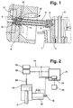
- the casting container (2) has a riser hole (4), the upper end of which is conical Has a receiving opening for inserting a mouthpiece body (5), which can be heated in a known manner and which on his a conical end facing away from the insertion opening (6) Has receptacle (7) for a nozzle tip (8) in the shape (9) protrudes, the sprue channels (10) in the actual Pass over the molding space (11).
- a metal sensor (13) which is connected via a connecting cable (14) is connected to a control device (15) which consists of the Fig. 2 can be seen.
- the metal beam reaches the metal sensor during the casting process (13) at the tip of the mouthpiece body (5), then in the exact course of the mold filling process is sensitive to be controlled. Uncertainties where the metal beam does not exist.
- the touch metal sensor shown could also be non-contact sensors be provided, which does not lead into the metal beam and must be sealed against it, but in Insert blind holes that are closed to the metal flow.
- Such sensors could e.g. Magnetic field sensors or also Be ultrasonic sensors.
- Fig. 2 shows that the piston rod (3) of the casting piston of a press cylinder (16) is guided, on the outflow side Valve (17) is arranged, which is known as a highly dynamic Continuous valve is formed.
- This valve (17) is operated via a two-stage pilot valve (18) if A corresponding pulse comes from the control device (15).
- the control device (15) is designed as digital control electronics trained and in it e.g. the setpoints for six Phases of the press-in process are saved for generation of a certain product.
- the control device (15) enables real-time control and maintains it Start impulses for this time control on the one hand from the metal sensor (13), but it can also be from a path-dependent one Obtained scanner (19) which e.g.
- a suitable device (20) is connected to the plunger of the press cylinder (16), so that whose position within the press cylinder (16) can be detected. It there is also the possibility of increasing the pressure at the nozzle tip by a sensor in the hydraulics and thus initiate the signal for the start of the second phase, in which increases the pressure significantly.
- Both the path dependent Values as well as the signals from the metal sensor (13) can be found in known manner also additionally a screen (21) are supplied with a graphic display of the respective Casting parameters enabled.
- the control device (15) can also be connected to a valve (22), which is one not shown, the form (11) downstream vacuum device is connected upstream and can prevent that from the evacuated metal flowing into the ventilation ducts Vacuum pump arrives.
- the control valve (17) on the drain side of the casting cylinder is attached, works in the filling phase as a speed control valve.
- the speed is a function programmed the pouring plunger position and the corresponding actual values can via the device (19) on the screen and be given to the control device.
- the continuous valve is a pressure control valve.
- the corresponding Setpoints for distance, speed and pressure are given to the control device entered. With those received from the metal sensor
- the control device (15) can signal exact real-time control cause the press-in process, which is independent of the bath level inside the tub (1).
Landscapes
- Engineering & Computer Science (AREA)
- Mechanical Engineering (AREA)
- Casting Support Devices, Ladles, And Melt Control Thereby (AREA)
- Casting Devices For Molds (AREA)
- Molds, Cores, And Manufacturing Methods Thereof (AREA)
- Injection Moulding Of Plastics Or The Like (AREA)
- Press Drives And Press Lines (AREA)
- Moulds For Moulding Plastics Or The Like (AREA)
Claims (6)
- Machine de coulée sous pression à chambre chaude, dans laquelle le processus d'injection est influencé par un dispositif de commande électronique, auquel sont transmis des signaux d'entrée provenant du dispositif d'injection, comprenant un récipient de coulée (2), immergé dans la masse en fusion et muni d'une forure verticale (4) et d'un corps de filière (5) attenant à celle-ci, qui est guidé dans le moule (9) par une tête de tuyère (8), caractérisée en ce que, dans la zone de la tête du corps de filière (5), il est prévu un capteur de métal (13) qui est relié avec le dispositif de commande (15) et lui transmet également des signaux d'entrée, et en ce qu'il est prévu des soupapes à action continue (17) très dynamiques avec des durées de connexion entre 1 et 5 ms, qui sont destinées à influencer le processus d'injection et qui sont actionnées par le dispositif de commande (15) et permettent de réguler la vitesse et la pression en fonction du produit.
- Machine de coulée sous pression à chambre chaude selon la revendication 1, caractérisée en ce qu'une tête de tuyère (8) peut être insérée dans un logement (7) du corps de filière (5) et en ce que le capteur de métal (13) est monté dans la cavité de réception (12) du corps de filière (5) pour la tête de tuyère (8).
- Machine de coulée sous pression à chambre chaude selon la revendication 1, caractérisée en ce que le moule (9) est associé à un dispositif d'évacuation muni d'une pompe à vide et d'une vanne (22) montée en amont de celle-ci, qui peut être actionnée par le dispositif de commande (15).
- Machine de coulée sous pression à chambre chaude selon la revendication 1, caractérisée en ce que les capteurs de métal prévus sont des capteurs qui réagissent sans contact à la présence du métal en fusion.
- Machine de coulée sous pression à chambre chaude selon la revendication 4, caractérisée en ce que le capteur de métal prévu est un capteur à champ magnétique.
- Machine de coulée sous pression à chantre chaude selon la revendication 1, caractérisée en ce que le capteur de métal prévu est un capteur électrique (13) qui pénètre avec une surface de contact dans le corps de filière (5).
Applications Claiming Priority (3)
| Application Number | Priority Date | Filing Date | Title |
|---|---|---|---|
| DE4419848 | 1994-06-07 | ||
| DE4419848A DE4419848C1 (de) | 1994-06-07 | 1994-06-07 | Warmkammer-Druckgießmaschine |
| PCT/EP1995/001963 WO1995033588A1 (fr) | 1994-06-07 | 1995-05-23 | Fonctionnement d'une machine a coulee sous pression a chambre chaude et machine a coulee sous pression appropriee |
Publications (2)
| Publication Number | Publication Date |
|---|---|
| EP0714331A1 EP0714331A1 (fr) | 1996-06-05 |
| EP0714331B1 true EP0714331B1 (fr) | 2000-03-22 |
Family
ID=6519979
Family Applications (1)
| Application Number | Title | Priority Date | Filing Date |
|---|---|---|---|
| EP95920872A Expired - Lifetime EP0714331B1 (fr) | 1994-06-07 | 1995-05-23 | Fonctionnement d'une machine a coulee sous pression a chambre chaude et machine a coulee sous pression appropriee |
Country Status (7)
| Country | Link |
|---|---|
| US (1) | US5699849A (fr) |
| EP (1) | EP0714331B1 (fr) |
| JP (1) | JP3824171B2 (fr) |
| AT (1) | ATE190880T1 (fr) |
| DE (2) | DE4419848C1 (fr) |
| ES (1) | ES2144612T3 (fr) |
| WO (1) | WO1995033588A1 (fr) |
Families Citing this family (9)
| Publication number | Priority date | Publication date | Assignee | Title |
|---|---|---|---|---|
| DE19649621B4 (de) * | 1996-11-29 | 2007-08-02 | EWIKON Heißkanalsysteme GmbH & Co KG | Verbindungsanordnung für Schmelzekanalabschnitte in Heißkanälen |
| ES2205643T3 (es) * | 1999-04-13 | 2004-05-01 | OSKAR FRECH GMBH & CO. | Maquina de colada a presion de camara caliente. |
| EP1097765A4 (fr) * | 1999-04-28 | 2005-02-09 | Sumitomo Metal Ind | Regulation du niveau de la surface du metal dans un moule en moulage continu |
| ATE291513T1 (de) * | 2000-10-27 | 2005-04-15 | Frech Oskar Gmbh & Co Kg | Warmkammerdruckgiessmaschine und betriebsverfahren hierfür |
| JP4175602B2 (ja) * | 2001-07-02 | 2008-11-05 | 徹一 茂木 | 鋳造用注湯装置 |
| ES2253309T3 (es) * | 2001-08-09 | 2006-06-01 | Oskar Frech Gmbh + Co. Kg | Procedimiento para el funcionamiento de una moldeadora a presion de camara caliente y moldeadora a presion. |
| CA2628504C (fr) | 2007-04-06 | 2015-05-26 | Ashley Stone | Dispositif de coulage |
| DE102011017610B3 (de) * | 2011-04-27 | 2012-06-21 | Oskar Frech Gmbh + Co. Kg | Gießkolben und Gießeinheit mit Absperrventil |
| DE102015000738B3 (de) * | 2015-01-21 | 2016-05-25 | Audi Ag | Warmkammer-Druckgussanlage |
Family Cites Families (11)
| Publication number | Priority date | Publication date | Assignee | Title |
|---|---|---|---|---|
| DE157168C (fr) * | 1903-05-23 | |||
| DE2143937B2 (de) * | 1971-09-02 | 1977-05-18 | Oskar Frech, Werkzeugbau, 7061 Weiler | Giessbehaelter fuer eine warmkammer- druckgiessmaschine |
| DD157168A1 (de) * | 1981-03-13 | 1982-10-20 | Gerhard Losemann | Vorrichtung zur hydraulischen geschwindigkeits-und druckregelung in spritzgiessmaschinen |
| DE3142811A1 (de) * | 1981-10-28 | 1983-05-05 | Idra Pressen GmbH, 7000 Stuttgart | Verfahren und vorrichtung zur regelung der giesskolbenbewegung waehrend des einpressvorganges an einer druckgiessmaschine |
| JPS6234659A (ja) * | 1985-08-09 | 1987-02-14 | Hitachi Metals Ltd | ダイカストマシンの射出速度切換え方法 |
| JPS6340661A (ja) * | 1986-08-01 | 1988-02-22 | Tanabe Kogyo Kk | 溶融金属の給湯装置 |
| DE3636936A1 (de) * | 1986-10-30 | 1988-05-05 | Buehler Ag Geb | Druck- oder spritzgiessmaschine |
| DE3917487A1 (de) * | 1989-05-30 | 1990-12-06 | Frech Oskar Gmbh & Co | Giessbehaelter fuer warmkammer-druckgiessmaschinen |
| US5125450A (en) * | 1990-05-07 | 1992-06-30 | Electrovert Ltd. | Method of and system for controlling flow of molten liquid to cast metal alloys |
| DE4216773A1 (de) * | 1992-05-21 | 1993-11-25 | Kurt Loeffler Druckgus Gmbh & | Druckgußvorrichtung |
| DE4218556A1 (de) * | 1992-06-05 | 1993-12-09 | Mueller Weingarten Maschf | Verfahren und Vorrichtung zur Durchführung des Verfahrens zur Prozeßsteuerung einer Druckgießmaschine |
-
1994
- 1994-06-07 DE DE4419848A patent/DE4419848C1/de not_active Expired - Fee Related
-
1995
- 1995-05-23 JP JP50026896A patent/JP3824171B2/ja not_active Expired - Lifetime
- 1995-05-23 US US08/592,348 patent/US5699849A/en not_active Expired - Lifetime
- 1995-05-23 WO PCT/EP1995/001963 patent/WO1995033588A1/fr not_active Ceased
- 1995-05-23 EP EP95920872A patent/EP0714331B1/fr not_active Expired - Lifetime
- 1995-05-23 AT AT95920872T patent/ATE190880T1/de active
- 1995-05-23 DE DE59508044T patent/DE59508044D1/de not_active Expired - Lifetime
- 1995-05-23 ES ES95920872T patent/ES2144612T3/es not_active Expired - Lifetime
Also Published As
| Publication number | Publication date |
|---|---|
| US5699849A (en) | 1997-12-23 |
| EP0714331A1 (fr) | 1996-06-05 |
| JPH09501360A (ja) | 1997-02-10 |
| WO1995033588A1 (fr) | 1995-12-14 |
| DE59508044D1 (de) | 2000-04-27 |
| DE4419848C1 (de) | 1995-12-21 |
| ATE190880T1 (de) | 2000-04-15 |
| ES2144612T3 (es) | 2000-06-16 |
| JP3824171B2 (ja) | 2006-09-20 |
Similar Documents
| Publication | Publication Date | Title |
|---|---|---|
| DE102004023150B4 (de) | Einspritzsystem und Gießverfahren einer Gießmaschine | |
| EP1761375B1 (fr) | Procede pour remplir au moins une cavite | |
| DE2302175C3 (de) | Vorrichtung zur Konstanthaltung des Formfüllgrades einer Spritzgießform an einer Kunststoff-Spritzgießmaschine | |
| DE2603891C3 (de) | Antrieb zum Bewegen eines Einspritzkolbens einer Druckgießmaschine | |
| EP0714331B1 (fr) | Fonctionnement d'une machine a coulee sous pression a chambre chaude et machine a coulee sous pression appropriee | |
| DE2757052A1 (de) | Vorrichtung zur niveauueberwachung und -steuerung des geschmolzenen metalls in der gussform einer strang-gussmaschine | |
| CH642904A5 (de) | Verfahren zur steuerung von duesenverschluessen in einer spritzgiessvorrichtung. | |
| DE3413665A1 (de) | Verfahren zur steuerung der spritzgeschwindigkeit eines spritzgusszylinders einer spritzgussmaschine | |
| DE2826060C3 (de) | Verfahren und Einrichtung zur Regelung einer NiederdruckgieSanlage | |
| DE3040762C2 (de) | Verfahren und Vorrichtung zur Einstellung der Masse von Posten thermoplastischen Materials | |
| DE3889126T2 (de) | Steuerungseinheit einer spritzgiessmaschine. | |
| EP1516687B1 (fr) | Procédé de coulée sous pression sous vide ou de moulage par injection sous vide | |
| EP1080809B1 (fr) | Méthode pour contrôler la distribution de quantité de métal liquide | |
| DE10346924A1 (de) | Linearer Stelltrieb mit Postionssensor für eine Spritzgießvorrichtung | |
| EP1912774A1 (fr) | Procede pour surveiller et/ou regler le remplissage d'au moins une cavite avec une matiere en fusion | |
| DE102009014311A1 (de) | Verfahren zur Überwachung und/oder Steuerung und/oder Regelung von Funktionen von und bei Spritzgiessmaschinen | |
| DE3638249C2 (fr) | ||
| DE1949637A1 (de) | Strangpresse | |
| DE3020076C2 (de) | Regelvorrichtung für eine automatische Gießanlage | |
| DE3636936A1 (de) | Druck- oder spritzgiessmaschine | |
| DE19508867A1 (de) | Druckgießmaschine | |
| EP0400274B1 (fr) | Récipient de coulée pour machines à couler sous pression à chambre chaude | |
| DE4433932A1 (de) | Druck- oder Spritzgießmaschine | |
| DE4114985A1 (de) | Verfahren zum nachverdichten und druck- oder spritzgiessmaschine hierfuer | |
| DE3801216A1 (de) | Verfahren und vorrichtung zum steuern von spritzgiessmaschinen |
Legal Events
| Date | Code | Title | Description |
|---|---|---|---|
| PUAI | Public reference made under article 153(3) epc to a published international application that has entered the european phase |
Free format text: ORIGINAL CODE: 0009012 |
|
| 17P | Request for examination filed |
Effective date: 19951230 |
|
| AK | Designated contracting states |
Kind code of ref document: A1 Designated state(s): AT CH DE ES FR GB GR IT LI NL PT SE |
|
| 17Q | First examination report despatched |
Effective date: 19980911 |
|
| GRAG | Despatch of communication of intention to grant |
Free format text: ORIGINAL CODE: EPIDOS AGRA |
|
| GRAG | Despatch of communication of intention to grant |
Free format text: ORIGINAL CODE: EPIDOS AGRA |
|
| GRAH | Despatch of communication of intention to grant a patent |
Free format text: ORIGINAL CODE: EPIDOS IGRA |
|
| GRAH | Despatch of communication of intention to grant a patent |
Free format text: ORIGINAL CODE: EPIDOS IGRA |
|
| GRAA | (expected) grant |
Free format text: ORIGINAL CODE: 0009210 |
|
| AK | Designated contracting states |
Kind code of ref document: B1 Designated state(s): AT CH DE ES FR GB GR IT LI NL PT SE |
|
| PG25 | Lapsed in a contracting state [announced via postgrant information from national office to epo] |
Ref country code: NL Free format text: LAPSE BECAUSE OF FAILURE TO SUBMIT A TRANSLATION OF THE DESCRIPTION OR TO PAY THE FEE WITHIN THE PRESCRIBED TIME-LIMIT Effective date: 20000322 Ref country code: GR Free format text: LAPSE BECAUSE OF NON-PAYMENT OF DUE FEES Effective date: 20000322 |
|
| REF | Corresponds to: |
Ref document number: 190880 Country of ref document: AT Date of ref document: 20000415 Kind code of ref document: T |
|
| REG | Reference to a national code |
Ref country code: CH Ref legal event code: EP |
|
| REG | Reference to a national code |
Ref country code: CH Ref legal event code: NV Representative=s name: PATENTANWALTSBUERO G. PETSCHNER |
|
| REF | Corresponds to: |
Ref document number: 59508044 Country of ref document: DE Date of ref document: 20000427 |
|
| ITF | It: translation for a ep patent filed | ||
| REG | Reference to a national code |
Ref country code: ES Ref legal event code: FG2A Ref document number: 2144612 Country of ref document: ES Kind code of ref document: T3 |
|
| PG25 | Lapsed in a contracting state [announced via postgrant information from national office to epo] |
Ref country code: PT Free format text: LAPSE BECAUSE OF FAILURE TO SUBMIT A TRANSLATION OF THE DESCRIPTION OR TO PAY THE FEE WITHIN THE PRESCRIBED TIME-LIMIT Effective date: 20000623 |
|
| GBT | Gb: translation of ep patent filed (gb section 77(6)(a)/1977) |
Effective date: 20000621 |
|
| ET | Fr: translation filed | ||
| NLV1 | Nl: lapsed or annulled due to failure to fulfill the requirements of art. 29p and 29m of the patents act | ||
| PLBE | No opposition filed within time limit |
Free format text: ORIGINAL CODE: 0009261 |
|
| STAA | Information on the status of an ep patent application or granted ep patent |
Free format text: STATUS: NO OPPOSITION FILED WITHIN TIME LIMIT |
|
| 26N | No opposition filed | ||
| REG | Reference to a national code |
Ref country code: GB Ref legal event code: IF02 |
|
| REG | Reference to a national code |
Ref country code: CH Ref legal event code: NV Representative=s name: ZIMMERLI, WAGNER & PARTNER AG |
|
| REG | Reference to a national code |
Ref country code: CH Ref legal event code: PFA Owner name: OSKAR FRECH GMBH & CO. Free format text: OSKAR FRECH GMBH & CO.#SCHORNDORFER STRASSE 32#73614 SCHORNDORF (DE) -TRANSFER TO- OSKAR FRECH GMBH & CO.#SCHORNDORFER STRASSE 32#73614 SCHORNDORF (DE) |
|
| PGFP | Annual fee paid to national office [announced via postgrant information from national office to epo] |
Ref country code: ES Payment date: 20120525 Year of fee payment: 18 |
|
| PGFP | Annual fee paid to national office [announced via postgrant information from national office to epo] |
Ref country code: AT Payment date: 20120521 Year of fee payment: 18 |
|
| PGFP | Annual fee paid to national office [announced via postgrant information from national office to epo] |
Ref country code: DE Payment date: 20130524 Year of fee payment: 19 Ref country code: SE Payment date: 20130521 Year of fee payment: 19 Ref country code: GB Payment date: 20130522 Year of fee payment: 19 Ref country code: CH Payment date: 20130522 Year of fee payment: 19 |
|
| PGFP | Annual fee paid to national office [announced via postgrant information from national office to epo] |
Ref country code: IT Payment date: 20130525 Year of fee payment: 19 Ref country code: FR Payment date: 20130604 Year of fee payment: 19 |
|
| REG | Reference to a national code |
Ref country code: CH Ref legal event code: NV Representative=s name: WAGNER PATENT AG, CH |
|
| REG | Reference to a national code |
Ref country code: DE Ref legal event code: R119 Ref document number: 59508044 Country of ref document: DE |
|
| REG | Reference to a national code |
Ref country code: CH Ref legal event code: PL |
|
| REG | Reference to a national code |
Ref country code: AT Ref legal event code: MM01 Ref document number: 190880 Country of ref document: AT Kind code of ref document: T Effective date: 20140523 |
|
| GBPC | Gb: european patent ceased through non-payment of renewal fee |
Effective date: 20140523 |
|
| PG25 | Lapsed in a contracting state [announced via postgrant information from national office to epo] |
Ref country code: CH Free format text: LAPSE BECAUSE OF NON-PAYMENT OF DUE FEES Effective date: 20140531 Ref country code: LI Free format text: LAPSE BECAUSE OF NON-PAYMENT OF DUE FEES Effective date: 20140531 Ref country code: SE Free format text: LAPSE BECAUSE OF NON-PAYMENT OF DUE FEES Effective date: 20140524 |
|
| REG | Reference to a national code |
Ref country code: SE Ref legal event code: EUG |
|
| PG25 | Lapsed in a contracting state [announced via postgrant information from national office to epo] |
Ref country code: AT Free format text: LAPSE BECAUSE OF NON-PAYMENT OF DUE FEES Effective date: 20140523 |
|
| REG | Reference to a national code |
Ref country code: FR Ref legal event code: ST Effective date: 20150130 |
|
| REG | Reference to a national code |
Ref country code: DE Ref legal event code: R119 Ref document number: 59508044 Country of ref document: DE Effective date: 20141202 |
|
| PG25 | Lapsed in a contracting state [announced via postgrant information from national office to epo] |
Ref country code: IT Free format text: LAPSE BECAUSE OF NON-PAYMENT OF DUE FEES Effective date: 20140523 Ref country code: DE Free format text: LAPSE BECAUSE OF NON-PAYMENT OF DUE FEES Effective date: 20141202 |
|
| PG25 | Lapsed in a contracting state [announced via postgrant information from national office to epo] |
Ref country code: FR Free format text: LAPSE BECAUSE OF NON-PAYMENT OF DUE FEES Effective date: 20140602 Ref country code: GB Free format text: LAPSE BECAUSE OF NON-PAYMENT OF DUE FEES Effective date: 20140523 |
|
| REG | Reference to a national code |
Ref country code: ES Ref legal event code: FD2A Effective date: 20150630 |
|
| PG25 | Lapsed in a contracting state [announced via postgrant information from national office to epo] |
Ref country code: ES Free format text: LAPSE BECAUSE OF NON-PAYMENT OF DUE FEES Effective date: 20140524 |