EP0713980A2 - Dispositif d'entraînement - Google Patents
Dispositif d'entraînement Download PDFInfo
- Publication number
- EP0713980A2 EP0713980A2 EP95113280A EP95113280A EP0713980A2 EP 0713980 A2 EP0713980 A2 EP 0713980A2 EP 95113280 A EP95113280 A EP 95113280A EP 95113280 A EP95113280 A EP 95113280A EP 0713980 A2 EP0713980 A2 EP 0713980A2
- Authority
- EP
- European Patent Office
- Prior art keywords
- drive device
- structural unit
- signal conductors
- node element
- node
- Prior art date
- Legal status (The legal status is an assumption and is not a legal conclusion. Google has not performed a legal analysis and makes no representation as to the accuracy of the status listed.)
- Granted
Links
Images

Classifications
-
- F—MECHANICAL ENGINEERING; LIGHTING; HEATING; WEAPONS; BLASTING
- F15—FLUID-PRESSURE ACTUATORS; HYDRAULICS OR PNEUMATICS IN GENERAL
- F15B—SYSTEMS ACTING BY MEANS OF FLUIDS IN GENERAL; FLUID-PRESSURE ACTUATORS, e.g. SERVOMOTORS; DETAILS OF FLUID-PRESSURE SYSTEMS, NOT OTHERWISE PROVIDED FOR
- F15B15/00—Fluid-actuated devices for displacing a member from one position to another; Gearing associated therewith
- F15B15/20—Other details, e.g. assembly with regulating devices
- F15B15/28—Means for indicating the position, e.g. end of stroke
- F15B15/2892—Means for indicating the position, e.g. end of stroke characterised by the attachment means
-
- F—MECHANICAL ENGINEERING; LIGHTING; HEATING; WEAPONS; BLASTING
- F15—FLUID-PRESSURE ACTUATORS; HYDRAULICS OR PNEUMATICS IN GENERAL
- F15B—SYSTEMS ACTING BY MEANS OF FLUIDS IN GENERAL; FLUID-PRESSURE ACTUATORS, e.g. SERVOMOTORS; DETAILS OF FLUID-PRESSURE SYSTEMS, NOT OTHERWISE PROVIDED FOR
- F15B15/00—Fluid-actuated devices for displacing a member from one position to another; Gearing associated therewith
- F15B15/20—Other details, e.g. assembly with regulating devices
- F15B15/28—Means for indicating the position, e.g. end of stroke
- F15B15/2807—Position switches, i.e. means for sensing of discrete positions only, e.g. limit switches
Definitions
- the invention relates to a drive device with two units which can be driven relative to one another, functional units such as sensors or valves being provided on the first of the two units for controlling and / or monitoring the relative movement between the two units, which have signal conductors integrated into the first unit are connected to a node element fixed to the first structural unit.
- functional units such as sensors or valves being provided on the first of the two units for controlling and / or monitoring the relative movement between the two units, which have signal conductors integrated into the first unit are connected to a node element fixed to the first structural unit.
- Such a drive device is shown in the form of a fluid-driven piston-cylinder unit from DE 39 23 063 C2.
- the first structural unit formed by a multi-part housing has a longitudinal groove in which sensors can be anchored.
- the sensor signals are routed via signal conductors integrated in the sensor groove in the form of conductor tracks to a node element plugged into the end, to which further electrical lines can be connected, which are connected to a Control device are connected.
- valves are integrated in the housing, which control the application of fluid to the piston of the piston-cylinder unit which forms the second structural unit, and which also lead via signal conductors in the housing to the node element, which in the concrete case is plate-shaped.
- the signals supplied by the sensors are processed in the control device, which then sends the necessary actuation signals to the valves.
- a considerable wiring effort is therefore required.
- the installation of a device which contains several of the piston-cylinder units described therefore requires a relatively large outlay and provides a large number of possible later sources of error in the operating sequence.
- the node element contains central signal processing electronics for the signals coming from the functional units and the signals to be transmitted to the functional units.
- the signal processing electronics integrated in the node element are designed as control electronics, which contain a preferably freely programmable control program and which directly takes over the control and monitoring of the drive device.
- the intelligence of the control is thus integrated into the drive device itself and controls, for example, depending on the sensor signals received, the actuation of likewise integrated valves which, in the case of a fluid-operated drive device, control the pressurization of the second structural unit.
- the signal processing electronics of the node element are designed as fieldbus communication electronics, which are connected via a serial fieldbus with a small number of wires to an external control device and forwards the control signals received by the latter to the relevant functional units with the correct assignment.
- the electronics can be a so-called ASI (Actor Sensor Interface) or a so-called LON (Local Operating Network).
- the subclaims contain advantageous configurations of the drive device.
- the node module can be a plug-in module, for example. It comprises a first set of contact elements which, when mounted on the first structural unit, wire simultaneously in connection with a second set of contact elements on the first structural unit, these contact elements being readily formed by signal conductors, for example conductor tracks. With the assembly of the node module, all connections relevant for signal transmission are expediently established at the same time, so that the connection effort is minimal.
- An expedient embodiment provides that there is a multiple arrangement of signal conductors on the first structural unit, which extends from the node element over the length of the first structural unit. This multiple arrangement of signal conductors can then be tapped or tapped at practically any point in order to make the signal connection to functional units arranged on the first structural unit at a suitable point.
- Such a multiple arrangement of signal conductors could, for example, consist of a multi-core ribbon cable which is installed in an anchoring groove extending along the first structural unit, the installation also being able to be carried out by the user, depending on the design.
- the sensor in order to connect a sensor to be fixed in the anchoring groove to the assigned signal conductors, the sensor can have lancing elements that pierce or press into the signal conductors when the sensor is fastened, thereby establishing the signal connection.
- a two-wire line is expediently sufficient, via which the required continuous operating voltage is supplied (for example 24 volts) and via which signals can also be transmitted, if required, which are superimposed on the voltage signal.
- all functional units provided on the drive device can + be connected centrally to the node element, which thus represents the only interface to the outside and makes the practical installation of the drive device relatively simple, even for non-specialists.
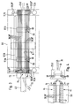
- the exemplary embodiment shows a drive device 1 which is designed as a linear drive 2 and has two structural units 3, 4 which can be moved in relation to one another in translation. It is expediently a fluid-actuated linear drive, the first structural unit 3 being formed by a housing 5 and the second structural unit 4 being formed by an output part 6 which can be driven in relation to the housing 5.
- the housing 5 contains one from FIG. 2 partially visible and preferably cylindrically contoured chamber 7, in which a piston 8 is arranged such that it can be moved linearly and is connected to a piston rod 12 which protrudes from the front of the housing 5.
- the piston 8 and the piston rod 12 represent the driven part 6.
- the housing 5 is provided with an end cover 13, 14 on both the front and the rear.
- two connection openings 15 are arranged, which communicate via internal channels with one of the two working spaces divided by the piston 8 in the chamber 7.
- a fluid in particular compressed air
- the driven part 6 can be driven relative to the housing 5 by the action of the piston 8 in a reciprocating linear movement in the direction of the longitudinal axis 16.
- An object to be moved can be attached to the outer end of the piston rod 12.
- the linear drive 2 can also be an electrical linear drive, furthermore the linear drive can be designed without a piston rod, the output part 6 being connected in another way to a component which is longitudinally displaceable on the outside of the housing and is suitable for power take-off.
- This can be a so-called slot cylinder or a band cylinder, or a rodless cylinder with magnetic coupling between the piston and the outer component.
- a plurality of functional units 17 are arranged on the housing 5 of the linear drive 2, which are used to control and monitor the Relative movement between the two units 3, 4 serve.
- Two of these functional units 17 are sensors 18 which respond to certain axial piston positions and which are actuated, for example, by a permanent magnet 22 arranged on the piston 8. These can include so-called reed sensors or magnetoresistive sensors.
- a functional unit 17 shown in FIG. 3 in addition to FIG. 1 is a position detection device 23 which, for example, enables a constant determination of the current piston position in an analog way. It extends along the piston stroke and can be based on an ultrasound working principle in which the duration of a sound wave in a magnetostrictive body is evaluated.
- valves 24 which can be designed as proportional valves or as switching valves and expediently have an electromagnet 25 which is schematically indicated in FIG. 2 and which functions as an actuating unit for the valve member.
- the valves 24 according to the example are configured in the manner of cartridges and, in particular, are completely embedded in a housing-side cavity 26, so that there are no disruptively protruding parts. These valves 24 are switched into the fluid channels inside the housing which are connected to the connection openings 15 and lead into the two working spaces of the linear drive 2. A fluid supply or discharge with respect to the connected work space can be controlled in accordance with the respective actuation of the valves 24.
- a node element 27 is provided in the area of the rear end of the housing 5. It is in signal connection with all of the functional units 17 via signal conductors 28 integrated in the housing 5. These signal conductors 28 are indicated by dashed lines in FIGS. 1 and 4, and are shown in solid lines in FIGS. 2 and 3. The designation node element was chosen because all signal conductors 28 converge centrally in this component. In this way, all of the monitoring signals supplied by the sensors 18 and the possibly present position detection device 23 are fed to the node element 27. Likewise, the valves 24 and other functional units 17 dependent on control signals receive their corresponding control signals from the node element 27.
- the node element 27 does not only form a simple transit station with a 1: 1 forwarding of the signals. Rather, it is equipped with central signal processing electronics 32, which processes the signals coming from the functional units 17 and the signals to be transmitted to the functional units 17.
- the signal processing electronics 32 are designed as fieldbus communication electronics 31, which mediate between the functional units 17 and an external control electronics 33.
- ASI Acceler Sensor Interface
- LON Land Operating Network
- the connection between the control electronics 33 and the fieldbus communication electronics 31 of the node element 27 can take place here via a two-wire line 34, via which a serial Signal or data exchange takes place.
- the signals supplied by the control electronics 33 are processed by the fieldbus communication unit 31 in such a way that they are forwarded with the correct assignment to the functional units 17 connected via the signal conductors 28.
- the signals coming from the functional units 17 are converted via the communication electronics 31 in such a way that they can be transmitted to the control electronics 33 in serial transmission mode with the smallest possible number of wires.
- the node element 27 is an integral part of the housing 5, it is advisable to connect the line connection 35 formed here by a two-wire line 34 to the node element 27 in the context of a detachable plug connection. A suitable interface is then provided on the node element 27.
- the fieldbus communication electronics 31 can be part of a fieldbus control device in which there are several drive devices, each of which is equipped with a suitable node element 27.
- the node element 27 expediently has a further interface which enables the connection of subsequent node elements.
- the two-wire line 34 is used at the same time to transmit the operating voltage to the node element 27 and further to the functional units 17.
- a voltage of 0 volt is present on one wire 36 and a voltage of 24 on the other wire 37, for example Volts on. This is preferably a permanent voltage.
- the tax and Monitoring signals can be modulated onto the operating voltage so that no additional wiring is required.
- control electronics 38 can also take place directly, which are integrated in the node element 27. If necessary, this even enables completely autonomous operation of the drive device 1 without additional external control electronics 33. It contains a control program in which the operating sequence of the drive device 1 is predetermined as a function of the monitoring signals supplied.
- a computer PC can be connected to the location of the application without any problems in order to be able to carry out the programming on site in a user-specific manner.
- connection of external control electronics 33 as coordination electronics makes sense if there are several drive devices in one machine, the operating processes of which must be coordinated with one another. Again, the transmission of the energy required for the operation of the signal processing electronics 32 and, if required, the functional units 17 can also take place here via the line connection 35.
- the drive device 1 can be equipped as required with further functional units 17 which are expediently integrated into the housing 5 as well as possible.
- sensors would also be conceivable for detecting the pressure in the work spaces, the acceleration and / or speed of the stripping part 6 and the pressure exerted Operating force.
- a pressure sensor 70 is indicated in FIG. 3, for example.
- the node element 27 is designed as a node module 42, which forms a compact component which is detachably fixed at a central connection point 43 of the housing 5.
- this connection point 43 is located on the rear side of the housing opposite the piston rod 12 and expediently on the associated rear cover 14.
- the connection point 43 is entirely variable and can be provided along the entire length of the housing in the exemplary embodiment as required.
- the signal conductors 28 comprise a multiple arrangement of signal conductors 28 'on the housing 5 forming the first structural unit 3, which extends parallel to the longitudinal axis 16 over practically the entire length of the housing. According to FIGS.
- said multiple arrangement in the exemplary embodiment comprises ten signal conductors 28 ', which are combined in two groups 44 of six signal conductors each, which each run between the two end caps 13, 14. It would be readily possible to design these signal conductors 28 'in the form of conductor tracks which are at least partially embedded in the housing 5 and each have a freely accessible tapping surface, via which tapping can take place in any longitudinal position by means of suitable contact elements.
- the two groups 44 of signal conductors 28 ' are each part of a multi-core ribbon cable 45, in which the individual wires form the different signal conductors 28' which are shown in FIG Band level run parallel to each other lying side by side.
- the signal conductors 44 are encased by the insulating body 46 of the ribbon cable 45.
- the ribbon cables 45 are fixed to the housing 5 and thus integrated into this, the attachment being able to be carried out in any way, for example by sticking or clamping.
- the signal conductors 28 ′ and, in the present case, the two ribbon cables 45 are laid in an anchoring groove 47, which is made in the housing 5 in the region of the outer circumference and extends parallel to the longitudinal axis 16.
- the anchoring groove 47 is open on both sides at the end, its end sections running in the end caps 13, 14.
- One or more functional units 17, which in the present case are the sensors 18 already mentioned, can be detachably fixed at any point in the anchoring groove 47.
- the exemplary embodiment provides that the node module 42 can also be releasably fixed in the anchoring groove 47.
- the measures taken for releasable anchoring in the anchoring groove 47 can be identical for the sensors 18 and the node module 42, so that the present description with reference to FIG. 2 is limited to the node module 42.
- the anchoring groove 47 is open on the longitudinal side toward an outer surface section 48 of the housing 5, which has a flat shape in particular.
- a groove neck 52 adjoins this outer surface section 48, followed by a wider anchoring section 53 in the depth direction, so that there is an overall T-groove.
- the node module 42 and the sensors 18 essentially have one complementary outer contouring and can be inserted into the anchoring groove 47 at the end.
- a wider fastening section 54 comes to lie in the anchoring section 53 and a centering section 55 protruding from the fastening section 54 projects into the groove neck 52.
- the height of the fastening section 54 is less than that of the anchoring section 53, so that the node module 42 or a respective sensor 18 can be moved in the depth direction of the anchoring groove 47 according to double arrow 56.
- a respective component 42, 18 is further penetrated in the vertical direction by at least one clamping element 57 formed in the exemplary embodiment by a threaded element, which has a clamping surface 59 opposite the base 58 of the anchoring groove 47 and an actuating part located in the region of the upper side of the centering section 55 and accessible from the outside 63 has.
- the latter allows a screwing tool to be attached in order to adjust the clamping element 57 in the vertical direction relative to the node module 42 or sensor 18.
- the fastening section 54 By screwing the tensioning element 57 against the base 58, the fastening section 54 is displaced in the opposite direction away from the base 58, the holding parts 64 of the fastening section 54 projecting laterally beyond the groove neck 52 from below against the ones laterally adjoining the groove neck 52 and the ground 58 facing holding surfaces 65 of the anchoring section 53 are pressed. In this way, the node module 42 or a respective sensor 18 is releasably clamped in the anchoring groove 47.
- the signal conductors 28 ' are expediently arranged in the anchoring section 53 and expediently on the one mentioned Holding surface 65 set.
- a multi-core ribbon cable 45 is attached to each of the two holding surfaces 65. When the respective component 42, 18 is clamped, it is thus pressed with its holding parts 64 against the ribbon cable 45.
- the node module 42 has on the top of its two holding parts 64 each a plurality of contact elements which are designed as piercing elements 66, each signal conductor 28 'being assigned at least one of its own piercing element 66 which, in the exemplary embodiment, is pin-like in the direction of the associated signal conductor 28'. protrudes.
- Lancing elements 66 are electrically connected to signal processing electronics 32 via module-internal conductors 67. All lancing elements 66 taken together form a first set 68 of contact elements.
- the tensioning element 57 is adjusted so that the node module 42 can be inserted into the anchoring groove 47 without damaging the ribbon cables 65 with the piercing elements 66.
- the tensioning element 47 is actuated, the lancing elements 66 being clamped into the respectively assigned signal conductor 28 'of the ribbon cable 45 when the fastening section 54 is tensioned push in.
- the insulating body 46 is pierced. In this way, electrical contact is established between the signal processing electronics 42 and the signal conductors.
- Each sensor 18 has a second set 69 of contact elements, which are also designed as lancing elements 66 and whose basic arrangement can correspond to that in the node module 42.
- the number of piercing elements 66 is, however, smaller in these second sets 69 of contact elements, the number suitably corresponds to the number of signal conductors 28 'to be connected. If it is not desired that a plurality of sensors 18 are connected to identical signal conductors 28 'at the same time, the second sets 69 of contact elements contain piercing elements 66 arranged at different distances, so that different signal conductors 28' are contacted.
- both the node module 42 and the sensors 18 can be positioned at different locations along the anchoring groove 47 and contacted at the corresponding location with the signal conductors 28, 28 '.
- the further functional units 17, in the present case the two valves 24 and the position detection device 23, are connected via signal conductors 28 ′′ to the signal conductors 28 ′, which run comparable to a data path along the second structural unit.
- a pressure sensor 70 being shown in FIG. 3 as an additional variant, which detects the fluid pressure of the operating fluid.
- These signal conductors 28 ′′ are preferably permanently installed in the second structural unit 4 and can also be connected to the signal conductors 28 ′ via, for example, contact elements 74 designed as piercing elements. Said contact elements 74 can be permanently installed in the region of the anchoring groove 47, so that the Assembly of the ribbon cable 45 automatically takes place. The arrangement is again such that contact is made with selected signal conductors 28 'in the correct assignment.
- FIG. 3 also shows that several or all of the signal conductors 28 ′ of the multiple arrangement of signal conductors can lead to a coupling point 75, to which a coupling element 73, only shown schematically, can be connected, which is connected to further signal conductors 72.
- a link to other devices can be made possible, which can also be controlled via the node element 27.
- the coupling point 75 can be designed such that an easy plug-in assembly is possible.
- FIG. 4 shows a construction variant in which the two groups 44 of signal conductors are designed in the form of conductor tracks, which are each arranged on a strip-like or strip-shaped circuit board 76 which, like the ribbon cables 45 of the other exemplary embodiment, are fixed in the anchoring groove 47 .
- the second set 69 of contact elements of the sensors 18, which are not shown here can consist of touch and / or sliding contacts which tap the assigned conductor tracks.
- the connection point 43 is assigned to one end of the second structural unit 4, where the signal conductors 28 ′ end in a third set 77 of contact elements provided on the printed circuit boards 76.
- the node module 42 is designed as a connector that is on the end can be plugged onto the printed circuit boards 76, the first set 68 of contact elements provided on it coming into contact and / or mating engagement with the third set 77 of contact elements mentioned.
- the drive device 1 can be equipped with further functional units 17 as required, it being possible for there to be further anchoring grooves which enable such functional units 17 to be fixed.
- these anchoring grooves can be equipped in the same way as the anchoring groove described, these further signal conductors being expediently connected to the aforementioned signal conductors 28 ′ via connecting conductors or to the central connection point 43, where the node element 27 is located.
- raised anchoring rails could also be used, in which case the multiple arrangement of signal conductors 28 'is expediently arranged on an anchoring rail.
- the anchoring grooves or anchoring rails can be attached to the second structural unit 4, so that a trouble-free retrofitting of conventional drive devices is possible.
Landscapes
- Engineering & Computer Science (AREA)
- Physics & Mathematics (AREA)
- Fluid Mechanics (AREA)
- Mechanical Engineering (AREA)
- General Engineering & Computer Science (AREA)
- Actuator (AREA)
Applications Claiming Priority (2)
| Application Number | Priority Date | Filing Date | Title |
|---|---|---|---|
| DE4438164A DE4438164A1 (de) | 1994-10-26 | 1994-10-26 | Antriebsvorrichtung |
| DE4438164 | 1994-10-26 |
Publications (3)
| Publication Number | Publication Date |
|---|---|
| EP0713980A2 true EP0713980A2 (fr) | 1996-05-29 |
| EP0713980A3 EP0713980A3 (fr) | 1997-03-26 |
| EP0713980B1 EP0713980B1 (fr) | 2001-12-12 |
Family
ID=6531688
Family Applications (1)
| Application Number | Title | Priority Date | Filing Date |
|---|---|---|---|
| EP95113280A Expired - Lifetime EP0713980B1 (fr) | 1994-10-26 | 1995-08-24 | Dispositif d'entraínement |
Country Status (2)
| Country | Link |
|---|---|
| EP (1) | EP0713980B1 (fr) |
| DE (2) | DE4438164A1 (fr) |
Cited By (7)
| Publication number | Priority date | Publication date | Assignee | Title |
|---|---|---|---|---|
| EP0985831A3 (fr) * | 1998-09-09 | 2000-09-13 | Festo AG & Co | Actionneur linéaire |
| EP1068932A3 (fr) * | 1999-07-16 | 2002-01-16 | Norgren Automotive Inc. | Soupape et système de contrôle de position intégrables dans un dispositif de serrage |
| WO2002031364A1 (fr) * | 2000-10-10 | 2002-04-18 | Festo Ag & Co | Systeme fonctionnant au moyen de fluide et ensemble soupape, ainsi qu'actionneur pour ledit systeme |
| WO2002068828A1 (fr) | 2001-02-22 | 2002-09-06 | Festo Ag & Co | Cylindre de travail |
| US6786127B2 (en) | 2000-03-17 | 2004-09-07 | Festo Ag & Co. | Fluid-actuated linear drive |
| US6973867B2 (en) | 2000-10-31 | 2005-12-13 | Festo Ag & Co. | Valve controlled fluidic actuator system |
| EP1746053A1 (fr) * | 2005-07-19 | 2007-01-24 | Helmut Wörner | Butée avec amortisseur |
Families Citing this family (4)
| Publication number | Priority date | Publication date | Assignee | Title |
|---|---|---|---|---|
| DE19623757A1 (de) * | 1996-06-14 | 1997-12-18 | Bosch Gmbh Robert | Druckmittelbetätigbarer Arbeitszylinder |
| DE29714454U1 (de) * | 1997-08-13 | 1997-10-23 | Festo Ag & Co | Regelanordnung zur Regelung von wenigstens einem an einem Bussystem angeschlossenen Positionierantrieb, insbesondere pneumatischen Positionierantrieb |
| DE102004023241B4 (de) * | 2004-05-07 | 2007-11-08 | Rexroth Mecman Gmbh | Einrichtung zur Positionserfassung |
| DE202006012815U1 (de) * | 2006-08-17 | 2007-12-20 | Mts Sensor Technologie Gmbh & Co. Kg | Weglängensensor |
Citations (1)
| Publication number | Priority date | Publication date | Assignee | Title |
|---|---|---|---|---|
| DE3923063A1 (de) | 1989-04-08 | 1990-10-11 | Festo Kg | Steuereinrichtung |
Family Cites Families (9)
| Publication number | Priority date | Publication date | Assignee | Title |
|---|---|---|---|---|
| DE7221036U (de) * | 1971-06-11 | 1975-07-31 | Sodeco Societe Des Compteurs De Gen | Elektrische Verbindungsklemme |
| DE3629367A1 (de) * | 1986-08-29 | 1988-03-03 | Rixen Wolfgang | Maschinelle behandlungsvorrichtung, insbesondere handhabungsautomat |
| ES2030811T3 (es) * | 1988-08-18 | 1992-11-16 | Festo Kg | Dispositivo lineal de impulsion. |
| DE3915456A1 (de) * | 1989-05-11 | 1990-11-15 | Herion Werke Kg | Schaltungsanordnung zur individuellen ansteuerung vorgegebener verbraucher |
| FR2651543B1 (fr) * | 1989-09-05 | 1991-12-06 | Roudaut Philippe | Ensemble piston-cylindre muni de moyens de determination et de validation de la position du piston. |
| SE465890B (sv) * | 1990-03-28 | 1991-11-11 | Mecman Ab | Kolvlaegesavkaennare |
| DE4039771A1 (de) * | 1990-12-13 | 1992-06-17 | Juergen Heesemann | Maschinensteuerung |
| DE9101734U1 (fr) * | 1991-02-15 | 1991-05-23 | Hygrama Ag, Rotkreuz, Ch | |
| DE4230414C2 (de) * | 1992-09-11 | 1996-02-01 | Festo Kg | Elektro-pneumatische Steuereinrichtung |
-
1994
- 1994-10-26 DE DE4438164A patent/DE4438164A1/de not_active Withdrawn
-
1995
- 1995-08-24 EP EP95113280A patent/EP0713980B1/fr not_active Expired - Lifetime
- 1995-08-24 DE DE59509935T patent/DE59509935D1/de not_active Expired - Fee Related
Patent Citations (1)
| Publication number | Priority date | Publication date | Assignee | Title |
|---|---|---|---|---|
| DE3923063A1 (de) | 1989-04-08 | 1990-10-11 | Festo Kg | Steuereinrichtung |
Cited By (10)
| Publication number | Priority date | Publication date | Assignee | Title |
|---|---|---|---|---|
| EP0985831A3 (fr) * | 1998-09-09 | 2000-09-13 | Festo AG & Co | Actionneur linéaire |
| EP1068932A3 (fr) * | 1999-07-16 | 2002-01-16 | Norgren Automotive Inc. | Soupape et système de contrôle de position intégrables dans un dispositif de serrage |
| US6557452B1 (en) | 1999-07-16 | 2003-05-06 | Norgren Automotive, Inc. | Valve and position control system integrable with clamp |
| US6786127B2 (en) | 2000-03-17 | 2004-09-07 | Festo Ag & Co. | Fluid-actuated linear drive |
| WO2002031364A1 (fr) * | 2000-10-10 | 2002-04-18 | Festo Ag & Co | Systeme fonctionnant au moyen de fluide et ensemble soupape, ainsi qu'actionneur pour ledit systeme |
| US6973867B2 (en) | 2000-10-31 | 2005-12-13 | Festo Ag & Co. | Valve controlled fluidic actuator system |
| WO2002068828A1 (fr) | 2001-02-22 | 2002-09-06 | Festo Ag & Co | Cylindre de travail |
| US6755115B2 (en) | 2001-02-22 | 2004-06-29 | Festo Ag & Co. | Working cylinder |
| EP1746053A1 (fr) * | 2005-07-19 | 2007-01-24 | Helmut Wörner | Butée avec amortisseur |
| US7299911B2 (en) | 2005-07-19 | 2007-11-27 | Helmut Worner | Abutment module |
Also Published As
| Publication number | Publication date |
|---|---|
| EP0713980B1 (fr) | 2001-12-12 |
| EP0713980A3 (fr) | 1997-03-26 |
| DE4438164A1 (de) | 1996-05-02 |
| DE59509935D1 (de) | 2002-01-24 |
Similar Documents
| Publication | Publication Date | Title |
|---|---|---|
| DE4004834C2 (de) | Ventilbaugruppe | |
| EP0608245B1 (fr) | Dispositif de commande electropneumatique | |
| DE4230414C2 (de) | Elektro-pneumatische Steuereinrichtung | |
| EP1350606B1 (fr) | Organe de préhension actionné par fluide | |
| EP1274945B1 (fr) | Cylindre de travail | |
| EP1013940B1 (fr) | Arrangement de soupape | |
| EP2466269B1 (fr) | Dispositif de capteur de position et dispositif d'entraînement linéaire en étant équipé | |
| EP0713980B1 (fr) | Dispositif d'entraínement | |
| EP0796519B1 (fr) | Dispositif de commande, notamment de commande de soupapes | |
| DE10338377A1 (de) | Magnetventil mit Anschlusskasten | |
| EP1134428A2 (fr) | Agencement de distributeur | |
| EP0708890B1 (fr) | Bloc de soupapes | |
| DE4320327C1 (de) | Aktuatoren oder Sensoren zum Anschluß an eine Busleitung | |
| EP0775835B1 (fr) | Appareil de détection de position | |
| CH710104A2 (de) | Dosiervorrichtung. | |
| EP0962663B1 (fr) | Dispositif de commande pour récepteurs actionnés par fluide | |
| EP0606048A1 (fr) | Distributeur fluidique | |
| EP0629783B1 (fr) | ContrÔle combiné de valves pneumatiques et hydrauliques | |
| EP1199479B1 (fr) | Dispositif hydropneumatique avec un dispositif diagnostique | |
| EP1309803B1 (fr) | Entrainement lineaire | |
| DE102004044497B3 (de) | Anschlussvorrichtung sowie damit ausgestattetes Ventil und Ventilbatterie | |
| DE10003961A1 (de) | Spannvorrichtung | |
| EP0930130B1 (fr) | Dispositif de serrage | |
| DE3923063A1 (de) | Steuereinrichtung | |
| EP1284371B1 (fr) | Assemblage de valves sous forme de matrice |
Legal Events
| Date | Code | Title | Description |
|---|---|---|---|
| PUAI | Public reference made under article 153(3) epc to a published international application that has entered the european phase |
Free format text: ORIGINAL CODE: 0009012 |
|
| AK | Designated contracting states |
Kind code of ref document: A2 Designated state(s): CH DE FR IT LI |
|
| PUAL | Search report despatched |
Free format text: ORIGINAL CODE: 0009013 |
|
| AK | Designated contracting states |
Kind code of ref document: A3 Designated state(s): CH DE FR IT LI |
|
| 17P | Request for examination filed |
Effective date: 19970320 |
|
| RAP1 | Party data changed (applicant data changed or rights of an application transferred) |
Owner name: FESTO AG & CO |
|
| 17Q | First examination report despatched |
Effective date: 19990615 |
|
| GRAG | Despatch of communication of intention to grant |
Free format text: ORIGINAL CODE: EPIDOS AGRA |
|
| GRAG | Despatch of communication of intention to grant |
Free format text: ORIGINAL CODE: EPIDOS AGRA |
|
| GRAH | Despatch of communication of intention to grant a patent |
Free format text: ORIGINAL CODE: EPIDOS IGRA |
|
| GRAH | Despatch of communication of intention to grant a patent |
Free format text: ORIGINAL CODE: EPIDOS IGRA |
|
| GRAA | (expected) grant |
Free format text: ORIGINAL CODE: 0009210 |
|
| AK | Designated contracting states |
Kind code of ref document: B1 Designated state(s): CH DE FR IT LI |
|
| REG | Reference to a national code |
Ref country code: CH Ref legal event code: NV Representative=s name: TROESCH SCHEIDEGGER WERNER AG Ref country code: CH Ref legal event code: EP |
|
| REF | Corresponds to: |
Ref document number: 59509935 Country of ref document: DE Date of ref document: 20020124 |
|
| ET | Fr: translation filed | ||
| PLBE | No opposition filed within time limit |
Free format text: ORIGINAL CODE: 0009261 |
|
| STAA | Information on the status of an ep patent application or granted ep patent |
Free format text: STATUS: NO OPPOSITION FILED WITHIN TIME LIMIT |
|
| 26N | No opposition filed | ||
| PGFP | Annual fee paid to national office [announced via postgrant information from national office to epo] |
Ref country code: DE Payment date: 20080912 Year of fee payment: 14 |
|
| PGFP | Annual fee paid to national office [announced via postgrant information from national office to epo] |
Ref country code: IT Payment date: 20080821 Year of fee payment: 14 Ref country code: FR Payment date: 20080818 Year of fee payment: 14 |
|
| PGFP | Annual fee paid to national office [announced via postgrant information from national office to epo] |
Ref country code: CH Payment date: 20081024 Year of fee payment: 14 |
|
| REG | Reference to a national code |
Ref country code: CH Ref legal event code: PL |
|
| PG25 | Lapsed in a contracting state [announced via postgrant information from national office to epo] |
Ref country code: LI Free format text: LAPSE BECAUSE OF NON-PAYMENT OF DUE FEES Effective date: 20090831 Ref country code: CH Free format text: LAPSE BECAUSE OF NON-PAYMENT OF DUE FEES Effective date: 20090831 |
|
| REG | Reference to a national code |
Ref country code: FR Ref legal event code: ST Effective date: 20100430 |
|
| PG25 | Lapsed in a contracting state [announced via postgrant information from national office to epo] |
Ref country code: FR Free format text: LAPSE BECAUSE OF NON-PAYMENT OF DUE FEES Effective date: 20090831 Ref country code: DE Free format text: LAPSE BECAUSE OF NON-PAYMENT OF DUE FEES Effective date: 20100302 |
|
| PG25 | Lapsed in a contracting state [announced via postgrant information from national office to epo] |
Ref country code: IT Free format text: LAPSE BECAUSE OF NON-PAYMENT OF DUE FEES Effective date: 20090824 |