EP0713959B1 - Abgasreinigungsvorrichtung für eine Brennkraftmaschine - Google Patents
Abgasreinigungsvorrichtung für eine Brennkraftmaschine Download PDFInfo
- Publication number
- EP0713959B1 EP0713959B1 EP95118457A EP95118457A EP0713959B1 EP 0713959 B1 EP0713959 B1 EP 0713959B1 EP 95118457 A EP95118457 A EP 95118457A EP 95118457 A EP95118457 A EP 95118457A EP 0713959 B1 EP0713959 B1 EP 0713959B1
- Authority
- EP
- European Patent Office
- Prior art keywords
- absorbent
- exhaust gas
- nox
- temperature
- amount
- Prior art date
- Legal status (The legal status is an assumption and is not a legal conclusion. Google has not performed a legal analysis and makes no representation as to the accuracy of the status listed.)
- Expired - Lifetime
Links
Images


Classifications
-
- F—MECHANICAL ENGINEERING; LIGHTING; HEATING; WEAPONS; BLASTING
- F01—MACHINES OR ENGINES IN GENERAL; ENGINE PLANTS IN GENERAL; STEAM ENGINES
- F01N—GAS-FLOW SILENCERS OR EXHAUST APPARATUS FOR MACHINES OR ENGINES IN GENERAL; GAS-FLOW SILENCERS OR EXHAUST APPARATUS FOR INTERNAL COMBUSTION ENGINES
- F01N3/00—Exhaust or silencing apparatus having means for purifying, rendering innocuous, or otherwise treating exhaust
- F01N3/08—Exhaust or silencing apparatus having means for purifying, rendering innocuous, or otherwise treating exhaust for rendering innocuous
- F01N3/0807—Exhaust or silencing apparatus having means for purifying, rendering innocuous, or otherwise treating exhaust for rendering innocuous by using absorbents or adsorbents
- F01N3/0828—Exhaust or silencing apparatus having means for purifying, rendering innocuous, or otherwise treating exhaust for rendering innocuous by using absorbents or adsorbents characterised by the absorbed or adsorbed substances
- F01N3/0842—Nitrogen oxides
-
- F—MECHANICAL ENGINEERING; LIGHTING; HEATING; WEAPONS; BLASTING
- F01—MACHINES OR ENGINES IN GENERAL; ENGINE PLANTS IN GENERAL; STEAM ENGINES
- F01N—GAS-FLOW SILENCERS OR EXHAUST APPARATUS FOR MACHINES OR ENGINES IN GENERAL; GAS-FLOW SILENCERS OR EXHAUST APPARATUS FOR INTERNAL COMBUSTION ENGINES
- F01N13/00—Exhaust or silencing apparatus characterised by constructional features ; Exhaust or silencing apparatus, or parts thereof, having pertinent characteristics not provided for in, or of interest apart from, groups F01N1/00 - F01N5/00, F01N9/00, F01N11/00
- F01N13/009—Exhaust or silencing apparatus characterised by constructional features ; Exhaust or silencing apparatus, or parts thereof, having pertinent characteristics not provided for in, or of interest apart from, groups F01N1/00 - F01N5/00, F01N9/00, F01N11/00 having two or more separate purifying devices arranged in series
-
- F—MECHANICAL ENGINEERING; LIGHTING; HEATING; WEAPONS; BLASTING
- F01—MACHINES OR ENGINES IN GENERAL; ENGINE PLANTS IN GENERAL; STEAM ENGINES
- F01N—GAS-FLOW SILENCERS OR EXHAUST APPARATUS FOR MACHINES OR ENGINES IN GENERAL; GAS-FLOW SILENCERS OR EXHAUST APPARATUS FOR INTERNAL COMBUSTION ENGINES
- F01N3/00—Exhaust or silencing apparatus having means for purifying, rendering innocuous, or otherwise treating exhaust
- F01N3/08—Exhaust or silencing apparatus having means for purifying, rendering innocuous, or otherwise treating exhaust for rendering innocuous
- F01N3/0807—Exhaust or silencing apparatus having means for purifying, rendering innocuous, or otherwise treating exhaust for rendering innocuous by using absorbents or adsorbents
- F01N3/0871—Regulation of absorbents or adsorbents, e.g. purging
-
- F—MECHANICAL ENGINEERING; LIGHTING; HEATING; WEAPONS; BLASTING
- F01—MACHINES OR ENGINES IN GENERAL; ENGINE PLANTS IN GENERAL; STEAM ENGINES
- F01N—GAS-FLOW SILENCERS OR EXHAUST APPARATUS FOR MACHINES OR ENGINES IN GENERAL; GAS-FLOW SILENCERS OR EXHAUST APPARATUS FOR INTERNAL COMBUSTION ENGINES
- F01N3/00—Exhaust or silencing apparatus having means for purifying, rendering innocuous, or otherwise treating exhaust
- F01N3/08—Exhaust or silencing apparatus having means for purifying, rendering innocuous, or otherwise treating exhaust for rendering innocuous
- F01N3/10—Exhaust or silencing apparatus having means for purifying, rendering innocuous, or otherwise treating exhaust for rendering innocuous by thermal or catalytic conversion of noxious components of exhaust
- F01N3/24—Exhaust or silencing apparatus having means for purifying, rendering innocuous, or otherwise treating exhaust for rendering innocuous by thermal or catalytic conversion of noxious components of exhaust characterised by constructional aspects of converting apparatus
- F01N3/30—Arrangements for supply of additional air
-
- F—MECHANICAL ENGINEERING; LIGHTING; HEATING; WEAPONS; BLASTING
- F01—MACHINES OR ENGINES IN GENERAL; ENGINE PLANTS IN GENERAL; STEAM ENGINES
- F01N—GAS-FLOW SILENCERS OR EXHAUST APPARATUS FOR MACHINES OR ENGINES IN GENERAL; GAS-FLOW SILENCERS OR EXHAUST APPARATUS FOR INTERNAL COMBUSTION ENGINES
- F01N9/00—Electrical control of exhaust gas treating apparatus
-
- F—MECHANICAL ENGINEERING; LIGHTING; HEATING; WEAPONS; BLASTING
- F02—COMBUSTION ENGINES; HOT-GAS OR COMBUSTION-PRODUCT ENGINE PLANTS
- F02D—CONTROLLING COMBUSTION ENGINES
- F02D41/00—Electrical control of supply of combustible mixture or its constituents
- F02D41/02—Circuit arrangements for generating control signals
- F02D41/021—Introducing corrections for particular conditions exterior to the engine
- F02D41/0235—Introducing corrections for particular conditions exterior to the engine in relation with the state of the exhaust gas treating apparatus
- F02D41/027—Introducing corrections for particular conditions exterior to the engine in relation with the state of the exhaust gas treating apparatus to purge or regenerate the exhaust gas treating apparatus
- F02D41/0275—Introducing corrections for particular conditions exterior to the engine in relation with the state of the exhaust gas treating apparatus to purge or regenerate the exhaust gas treating apparatus the exhaust gas treating apparatus being a NOx trap or adsorbent
-
- F—MECHANICAL ENGINEERING; LIGHTING; HEATING; WEAPONS; BLASTING
- F01—MACHINES OR ENGINES IN GENERAL; ENGINE PLANTS IN GENERAL; STEAM ENGINES
- F01N—GAS-FLOW SILENCERS OR EXHAUST APPARATUS FOR MACHINES OR ENGINES IN GENERAL; GAS-FLOW SILENCERS OR EXHAUST APPARATUS FOR INTERNAL COMBUSTION ENGINES
- F01N2240/00—Combination or association of two or more different exhaust treating devices, or of at least one such device with an auxiliary device, not covered by indexing codes F01N2230/00 or F01N2250/00, one of the devices being
- F01N2240/18—Combination or association of two or more different exhaust treating devices, or of at least one such device with an auxiliary device, not covered by indexing codes F01N2230/00 or F01N2250/00, one of the devices being an adsorber or absorber
-
- F—MECHANICAL ENGINEERING; LIGHTING; HEATING; WEAPONS; BLASTING
- F01—MACHINES OR ENGINES IN GENERAL; ENGINE PLANTS IN GENERAL; STEAM ENGINES
- F01N—GAS-FLOW SILENCERS OR EXHAUST APPARATUS FOR MACHINES OR ENGINES IN GENERAL; GAS-FLOW SILENCERS OR EXHAUST APPARATUS FOR INTERNAL COMBUSTION ENGINES
- F01N2390/00—Arrangements for controlling or regulating exhaust apparatus
- F01N2390/02—Arrangements for controlling or regulating exhaust apparatus using electric components only
-
- F—MECHANICAL ENGINEERING; LIGHTING; HEATING; WEAPONS; BLASTING
- F01—MACHINES OR ENGINES IN GENERAL; ENGINE PLANTS IN GENERAL; STEAM ENGINES
- F01N—GAS-FLOW SILENCERS OR EXHAUST APPARATUS FOR MACHINES OR ENGINES IN GENERAL; GAS-FLOW SILENCERS OR EXHAUST APPARATUS FOR INTERNAL COMBUSTION ENGINES
- F01N2430/00—Influencing exhaust purification, e.g. starting of catalytic reaction, filter regeneration, or the like, by controlling engine operating characteristics
- F01N2430/06—Influencing exhaust purification, e.g. starting of catalytic reaction, filter regeneration, or the like, by controlling engine operating characteristics by varying fuel-air ratio, e.g. by enriching fuel-air mixture
-
- F—MECHANICAL ENGINEERING; LIGHTING; HEATING; WEAPONS; BLASTING
- F02—COMBUSTION ENGINES; HOT-GAS OR COMBUSTION-PRODUCT ENGINE PLANTS
- F02D—CONTROLLING COMBUSTION ENGINES
- F02D2200/00—Input parameters for engine control
- F02D2200/02—Input parameters for engine control the parameters being related to the engine
- F02D2200/08—Exhaust gas treatment apparatus parameters
- F02D2200/0802—Temperature of the exhaust gas treatment apparatus
-
- Y—GENERAL TAGGING OF NEW TECHNOLOGICAL DEVELOPMENTS; GENERAL TAGGING OF CROSS-SECTIONAL TECHNOLOGIES SPANNING OVER SEVERAL SECTIONS OF THE IPC; TECHNICAL SUBJECTS COVERED BY FORMER USPC CROSS-REFERENCE ART COLLECTIONS [XRACs] AND DIGESTS
- Y02—TECHNOLOGIES OR APPLICATIONS FOR MITIGATION OR ADAPTATION AGAINST CLIMATE CHANGE
- Y02C—CAPTURE, STORAGE, SEQUESTRATION OR DISPOSAL OF GREENHOUSE GASES [GHG]
- Y02C20/00—Capture or disposal of greenhouse gases
- Y02C20/10—Capture or disposal of greenhouse gases of nitrous oxide (N2O)
-
- Y—GENERAL TAGGING OF NEW TECHNOLOGICAL DEVELOPMENTS; GENERAL TAGGING OF CROSS-SECTIONAL TECHNOLOGIES SPANNING OVER SEVERAL SECTIONS OF THE IPC; TECHNICAL SUBJECTS COVERED BY FORMER USPC CROSS-REFERENCE ART COLLECTIONS [XRACs] AND DIGESTS
- Y02—TECHNOLOGIES OR APPLICATIONS FOR MITIGATION OR ADAPTATION AGAINST CLIMATE CHANGE
- Y02T—CLIMATE CHANGE MITIGATION TECHNOLOGIES RELATED TO TRANSPORTATION
- Y02T10/00—Road transport of goods or passengers
- Y02T10/10—Internal combustion engine [ICE] based vehicles
- Y02T10/40—Engine management systems
Definitions
- the present invention relates to an exhaust gas purification device for an engine.
- WO 93-07363 discloses an exhaust gas purification device which is capable of removing NO X components in the exhaust gas of a lean burn engine (i.e., an internal combustion engine mainly operated at an air-fuel ratio higher than the stoichiometric air-fuel ratio).
- a NO X absorbent which absorbs NO X components in the exhaust gas when the air-fuel ratio of the exhaust gas is lean and releases the absorbed NO X when the oxygen concentration in the exhaust gas becomes low is disposed in the exhaust passage of the engine.
- the NO X absorbent Since the air-fuel ratio of the exhaust gas, in the most part of the operating range, is lean in the lean burn engine, the NO X absorbent usually absorbs the NO X components in the exhaust gas, thereby the NO X components are removed from the exhaust gas.
- the air-fuel ratio of the engine is lowered to make the air-fuel ratio of the exhaust, gas rich or stoichiometric when the amount of the NO X absorbed and accumulated in the NO X absorbent increases.
- the air-fuel ratio of the exhaust gas becomes rich or stoichiometric, the oxygen concentration in the exhaust gas falls rapidly and, at the same time, the concentration of HC (hydrocarbons) and CO (carbon monoxide) components in the exhaust gas becomes high.
- NO X accumulated in the NO X absorbent is released from the absorbent and reduced to N 2 by the HC, CO components in the exhaust gas.
- This process for causing the releasing of the absorbed NO X from the NO X absorbent and reducing the released NO X is called "a regenerating process for the NO X absorbent".
- the NO X components are removed from the exhaust gas by repeating the absorbing process and the regenerating process alternately during the engine operation.
- the concentration of the oxygen is low enough to cause the releasing of NO X from the NO X absorbent, but the concentration of HC and CO components in the exhaust gas is not sufficiently high to reduce all the NO X released from the NO X absorbent (or the concentration of the oxygen is still not sufficiently low to cause a reducing reaction). Therefore, a portion of the NO X released from the NO X absorbent flows out from the NO X absorbent without being reduced.
- the air-fuel ratio within the NO X absorbent becomes sufficiently rich to reduce all the NO X released from the NO X absorbent when a certain time lapses after the regenerating process starts and the outflow of NO X components terminates.
- the outflow of NO X occurs every time when the regenerating process starts, this causes an increase in the total emission of NO X .
- Document EP 0 560 991 A1 discloses a device for purifying exhaust gas of an internal combustion engine.
- This device comprises a NOx absorbent disposed in the exhaust gas path wherein exhaust gas flows constantly through said absorbent during the operation of the engine.
- the NOx absorbent absorbs NOx when an air-fuel ratio of exhaust gas flowing into said absorbent is lean and discharges NOx having been absorbed therein when an air-fuel ratio of the exhaust gas becomes equal to the theoretical air-fuel ratio or rich.
- the air-fuel ratio of the exhaust gas flowing into the NOx absorbent is periodically made equal to the theoretical one or rich to discharge absorbed NOx.
- an exhaust gas purification system for an internal combustion engine comprising a lean NOx catalyst installed in the exhaust conduit and a HC amount increasing device capable of increasing an amount of HC included in exhaust gas flowing to the lean NOx catalyst.
- the HC is supplied as a reducing substance to increase the NOx purification rate of the lean NOx catalyst.
- the HC amount is not continuously but intermittently increased to suppress the increase in HC emissions and thermal degradation of the lean NOx catalyst.
- the object underlying the invention is to provide an exhaust gas purification device for an internal combustion engine which is able to absorb NOx during lean operation and releases the absorbed NOx, and to regenerate the catalyst absorbing NOx during the operation of the engine.
- a detecting means for detecting the amount of NOx accumulated in the NOx absorbent is provided and a regenerating means for causing the air-fuel ratio of the exhaust gas flowing into the NOx absorbent to become rich or stoichiometric and thereby causing the NOx accumulated in the NOx absorbent to be released from the NOx absorbent and to be reduced , wherein the regenerating means is activated by an activating means at a timing determined by the amount of NOx accumulated in the absorbent only when the temperature of the NOx absorbent is lower than a predetermined temperature.
- a detecting means for detecting the amount of NOx accumulated in the NOx absorbent is provided in the regenerating means for causing the air fuel ratio of the exhaust gas flowing into the NOx absorbent to become rich or stoichiometric and thereby causing the NOx accumulated in the NOx absorbent to be released from the NOx absorbent and to be reduced wherein the regenerating means is activated by an activating means at a timing determined by the amount of NOx accumulated in the absorbent when the temperature of the NOx absorbent is lower than a predetermined temperature wherein, in case that the temperature of the NOx absorbent is higher than the predetermined temperature, the regenerating means is activated if the amount CR of the NOx accumulated in the NOx absorbent reaches a predetermined value CR1.
- the regeneration control means activates the regenerating means only when the temperature of the NO X absorbent is lower than a predetermined temperature.
- This predetermined temperature is selected so that the amount of the NO X that flows out from the NO X absorbent at the beginning of the regenerating process decreases to a practically negligible level at this temperature. Therefore, the regenerating process of the NO X absorbent is always started at the temperature lower than the predetermined temperature, to thereby minimized the outflow of NO X .
- the timing of the activation of the regenerating means is delayed as the temperature of the NO X absorbent becomes high. Therefore, the regenerating process is carried out less frequently when the temperature of the NO X absorbent is high. Thus, the total amount of NO X emission is minimized since the regeneration of the NO X absorbent at a high temperature, in which a larger amount of NO X flows out from the NO X absorbent, is carried out less frequently than that at a low temperature.
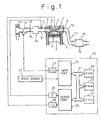
- Fig. 1 schematically illustrates an embodiment of the exhaust gas purification device according to the present invention.
- reference numeral 1 represents an internal combustion engine for an automobile.
- the engine 1 is a multiple cylinder type engine, and Fig. 1 shows one of the cylinders of the engine 1.
- the respective cylinders are provided with a combustion chamber 3, a piston 2, an ignition plug 4, an intake port 6 with an intake valve 6 and an exhaust port 8 with an exhaust valve 7.
- the intake ports 6 of the respective cylinders are connected to a surge tank 10 by an intake manifold 9, and on the intake manifold 9, a fuel injection valve 11 is disposed near the intake port of the respective cylinders to inject a pressurized fuel into the intake port 6 of the respective cylinders.
- the surge tank 10 is connected to an intake air filter 14 via an intake air duct 12 and an air-flow meter 13. 15 represents a throttle valve disposed on the intake air duct 12.
- the exhaust ports 8 of the respective cylinders are connected to a common exhaust pipe 17 by means of an exhaust manifold 16.
- a casing 19 containing a NO X absorbent 18 is disposed on the exhaust pipe 17, a casing 19 containing a NO X absorbent 18 is disposed.
- the NO X absorbent 18 will be explained later in detail.
- Reference numeral 30 in Fig. 1 represents a control circuit of the engine 1.
- the control circuit 30 consists of, for example, a digital computer provided with a ROM (read only memory) 32, a RAM (random access memory) 33, a CPU (microprocessor) 34, an input port 35 and an output port 36, which are interconnected by a bi-directional bus 31.
- ROM read only memory
- RAM random access memory
- CPU microprocessor
- the airflow meter 13 is, for example, a potentiometer-type which generates an analog voltage signal proportional to the amount of air flowing therethrough and drawn into the engine 1.
- the signal from the airflow meter 13 is transmitted to the input port 35 of the control circuit 30 through an analog-to-digital (A/D) converter 37. Further, pulse signals representing the rotational speed of the engine 1 are transmitted to the input port 35 from a speed sensor 23 disposed near the crankshaft of the engine 1.
- the output port 36 is connected to the fuel injection valve 11 and the ignition plug 4 of the respective cylinders via a driving circuit 39 and an ignition circuit 38, respectively.
- the base fuel injection amount TP is an amount of the fuel required to maintain the air-fuel ratio of the air-fuel mixture in the combustion chamber at the stoichiometric air-fuel ratio.
- the value of the base fuel injection amount TP is determined by, for example, an experiment using an actual engine, and stored in the ROM 32 of the control circuit 30 in the form of a numerical table based on the engine load conditions (such as the amount of intake air per one revolution of the engine, Q/N and engine speed N) as parameters.
- Fig. 2 shows a typical form of the numerical table used for calculating the base fuel injection amount TP.
- the correction factor Kt is used for adjusting the operating air-fuel ratio (the air-fuel ratio of the air-fuel mixture supplied to the combustion chambers of the engine 1).
- Kt is set at 1.0
- the operating air-fuel ratio of the engine becomes the stoichiometric air-fuel ratio.
- the correction factor Kt is set at Kt ⁇ 1.0, the operating air-fuel ratio of the engine becomes higher than the stoichiometric air-fuel ratio, i.e., the engine is operated at a lean air-fuel ratio.
- the correction factor Kt is set at Kt > 1.0, the operating air-fuel ratio of the engine becomes lower than the stoichiometric air-fuel ratio, i.e., the engine 1 is operated at a rich air-fuel ratio.
- Fig. 3 schematically illustrates the changes in the concentrations of O 2 and unburned HC, CO components of the exhaust gas in accordance with the operating air-fuel ratio of the engine 1.
- the concentrations of unburned HC and CO components increase as the operating air-fuel ratio of the engine becomes rich, and the concentration of the O 2 component increases as the operating air-fuel ratio becomes lean.
- the NO X absorbent 18 in this embodiment uses, for example, alumina as a carrier and, on this carrier, precious metals such as platinum Pt rhodium Rh, and at least one substance selected from alkali metals such as potassium K, sodium Na, lithium Li and cesium Cs; alkali-earth metals such as barium Ba and calcium Ca; and rare-earth metals such as lanthanum La and yttrium Y are carried.
- the NO X absorbent 18 absorbs NO X in the exhaust gas flowing into the NO X absorbent when the air-fuel ratio of the exhaust gas is lean, and releases the absorbed NO X when the oxygen concentration of the exhaust gas flowing the NO X absorbent becomes lower.
- air-fuel ratio of the exhaust gas means a ratio of the amounts of the air and the fuel supplied to the engine or exhaust passages upstream of the NO X absorbent 18. Therefore, when no air and fuel is supplied in the exhaust passage upstream of the NO X absorbent 18, the air-fuel ratio of the exhaust gas becomes the same as the operating air-fuel ratio of the engine (i.e., the air-fuel ratio of the air-fuel mixture supplied to combustion chambers of the engine).
- the NO X absorbent When the NO X absorbent is disposed in the exhaust passage of the engine, the NO X absorbent actually performs the above-mentioned absorption and releasing operation of NO X .
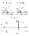
- the mechanism of this absorption and releasing operation of the NO X absorbent is not clear at present, it is considered that the absorption and releasing operation is conducted by the mechanism shown in Figs. 4A and 4B.
- Figs. 4A and 4B explain the mechanism of the absorption and the releasing operation in the case where platinum Pt and barium Ba are carried on the carrier, as an example, but it is considered that a similar mechanism also applies even if other precious metal, alkali metals, alkali earth metals, or rare earth metals are used.
- the concentration of oxygen in the exhaust gas becomes quite high.
- the oxygen O 2 is deposited on the surface of platinum Pt in the form of O 2 - or O 2- .
- the NO in the exhaust gas reacts with O 2 - or O 2- on the surface of the platinum Pt and becomes NO 2 (2NO + O 2 ⁇ 2NO 2 ).
- a part of the produced NO 2 is oxidized on the platinum Pt and absorbed into the NO X absorbent. While bonding with the barium oxide BaO, it is diffused in the absorbent in the form of nitric acid ions NO 3 - as shown in Fig. 4A. In this way, NO X is absorbed in the NO X absorbent.
- the NO X is produced on the surface of the platinum Pt, and as long as the NO X is produced on the surface of the platinum Pt, and as long as the NO X absorption capacity of the absorbent is not saturated, the NO X is absorbed into the NO X absorbent and nitric acid ions NO 3 - are produced.
- NO X is released from the NO X absorbent when the air-fuel ratio of the exhaust gas approaches to the stoichiometric air-fuel ratio.
- the HC and CO component in the exhaust gas immediately react with the O 2 - or O 2- on the platinum Pt and are oxidized, and subsequently if the HC and CO still remain after the O 2 - or O 2- on the platinum Pt are consumed, the NO X released from the absorbent and the NO X emitted from the engine are reduced.
- Kt 0.7
- the NO X accumulated in the NO X absorbent is released from the NO X absorbent and reduced, i.e., the NO X absorbent is regenerated and recovers the capability for absorbing NO X
- Fig. 5 shows the settings of the correction factor Kt during the regeneration process of the NO X absorbent.
- the value of the correction factor Kt is set at larger value KK (KK > 1.0) to shift the air-fuel ratio of the exhaust gas flowing into the NO X absorbent 18 to rich compared to the stoichiometric air-fuel ratio.
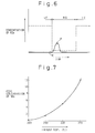
- Fig. 6 schematically illustrates this outflow of NO X from the NO X absorbent at the beginning of the regenerating process.
- the vertical axis represents the concentration of NO X in the exhaust gas
- the horizontal axis represents time.
- the dotted line in Fig. 6 represents the concentration of the NO X in the exhaust gas flowing into the NO X absorbent 18, and the solid line represents the same in the exhaust gas flowing out from the NO X absorbent 18. Further, the period indicated by LE in Fig.
- the period indicated by RG represents the regenerating period of the NO X absorbent (i.e., the period in which the engine is operated at a rich air-fuel ratio).
- the concentration of NO X in the exhaust gas flowing into the NO X absorbent 18 (dotted line in Fig. 6) is relatively high, but the same in the exhaust gas flowing out from the NO X absorbent 18 (solid line in Fig. 6) is very low since substantially all of the NO X in the exhaust gas is absorbed by the NO X absorbent 18.
- the concentration of NO X in the exhaust gas flowing into the NO X absorbent 18 becomes low since the amount of the NO X emitted from the engine 1 becomes small during a rich air-fuel ratio operation.
- the concentration of NO X in the exhaust gas flowing out from the NO X absorbent 18 increases temporarily immediately after the air-fuel ratio of the exhaust gas flowing into the NO X absorbent shifts to a rich air-fuel ratio at the point R in Fig. 6.
- This increase in the NO X in the exhaust gas flowing out from the NO X absorbent 18 lasts only for a short time and the concentration of NO X becomes very low after passing a peak value at the point P in Fig. 6.
- the peak value of the concentration of the NO X in the exhaust gas flowing out from the NO X absorbent 18 depends on the temperature of the NO X absorbent 18 when the regenerating process started.
- Fig. 7 shows the peak value of the amount of the NO X flowing out from the NO X absorbent measured at different temperatures of the NO X absorbent.
- the NO X absorbent used in the measurement in Fig. 7 has a substrate having a volume of 1.7 liters, and uses 2.0 g/liter of platinum Pt, 0.1 g/liter of rhodium Rh, 0.3 g/liter of barium Ba, and 0.1 g/liter of lithium Li.
- platinum Pt platinum Pt
- 0.1 g/liter of rhodium Rh 0.3 g/liter of barium Ba
- lithium Li lithium Li
- the vertical axis in Fig. 7 uses the peak value of the concentration of the NO X in the exhaust gas flowing out from the NO X absorbent (the concentration at the point P in Fig. 6) as a representative of the amount of outflow NO X
- the horizontal axis in Fig. 7 uses the temperature of the exhaust gas flowing into the NO X absorbent as a representative of the temperature of NO X absorbent.
- the amount of outflow NO X decreases as the temperature of the NO X absorbent becomes lower and, in the case of Fig. 7, the amount of outflow NO X becomes almost negligible when the temperature of the NO X absorbent (exhaust gas temperature) is lower than 200 degrees centigrade.
- the regenerating process in this embodiment is performed only when the temperature of the NO X absorbent is lower than the temperature at which the outflow of the NO X practically does not occur (for example, lower than 200°C in case of Fig. 7).
- the temperature of the NO X absorbent is determined by the temperature of the exhaust gas flowing into the NO X absorbent, and the exhaust gas temperature of the engine is determined by the operating conditions of the engine (such as the amount of the intake air per one revolution of the engine Q/N and engine speed N). Therefore, the exhaust gas temperature of the engine can be calculated from the operating conditions of the engine.
- the relationship between the temperature of the NO X absorbent 18 and operating conditions of the engine 1 is obtained, for example, by experiment, and this relationship is stored in the ROM 32 in control circuit 30.
- control circuit 30 calculates the temperature of the NO X absorbent from the operating conditions of the engine and performs the regenerating process when the temperature of the NO X absorbent is lower than the temperature at which the outflow of NO X practically does not occur.
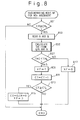
- Fig. 8 shows a flowchart explaining the regenerating process of the NO X absorbent 18 in this embodiment. This routine is performed by the control circuit 30 at predetermined intervals.
- step 801 in Fig. 8 it is determined whether it is necessary to start the regenerating process of the NO X absorbent 18 based on the value of the counter CR.
- the value of the counter CR represents the amount of NO X accumulated in the NO X absorbent in this embodiment. If the value of the counter CR is larger than or equal to a predetermined value CR 0 at step 801, since this means that the amount of NO X accumulated in the NO X absorbent becomes large, it is determined that the regenerating process should be started.
- the control circuit 30 increases the value of the counter CR by a predetermined amount at a regular intervals by a routine, not shown, during the lean air-fuel ratio operation of the engine. Therefore, the value of CR corresponds to the amount of NO X accumulated in the NO X absorbent.
- CR may be increased every time when the engine rotates a predetermined number of times.
- the amount of NO X emitted from the engine changes in accordance with the operating conditions of the engine (such as Q/N and N). Since the amount of NO X accumulated in the NO X absorbent is considered to increase in accordance with the cumulative amount of NO X emitted from the engine, the amount of NO X accumulated in the NO X absorbent can be more precisely estimated by calculating a total amount of NO X emitted from the engine. Therefore, the amount of NO X accumulated in the NO X absorbent can be calculated by cumulating the amount of NO X emitted from the engine multiplied by a constant factor.
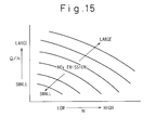
- Fig. 15 shows a typical change in the amount of NO X emitted from an internal combustion engine in accordance with the operating conditions.
- the vertical axis represents the amount of intake air drawn by the engine per one revolution of the engine (Q/N), and the horizontal axis represents the engine speed (N).
- the curves in Fig. 15 shows the amount of NO X emitted from the engine per unit time.
- Q/N is constant
- the amount of NO X emitted from the engine increases as the engine speed N increases
- the engine speed N is constant, the amount of NO X increases as Q/N increases.
- the amount of NO X emitted from the engine per unit time as shown in Fig. 15 is stored in the ROM 32 in control circuit 30 in the form of a numerical table based on Q/N and N which is similar to the numerical table in Fig. 2.
- the amount of NO X is read from the numerical table at regular intervals using measured Q/N and N, and the amount of NO X accumulated in the NO X absorbent is obtained as a cumulative value of the amount of NO X read from the table. This cumulative value can be used as the parameter of the amount of the NO X accumulated in the NO X absorbent at step 801 instead of the counter CR.
- Fig. 11 shows changes in the amount of the NO X accumulated in the NO X absorbent and in the concentration of NO X in the exhaust gas flowing out from the NO X absorbent in accordance with the time lapsed after the absorbing operation of the NO X absorbent.
- the curve (a) in Fig. 11 shows the amount of the NO X accumulated in the NO X absorbent.
- the amount of the NO X accumulated in the NO X absorbent increases as the time after the absorption of NO X starts, and when the amount of the NO X accumulated in the NO X absorbent reaches a saturated amount (indicated by SA in Fig. 11), the NO X absorbent cannot absorb the NO X in the exhaust gas any more.
- the curve (b) in Fig. 11 shows the concentration of the NO X in the exhaust gas downstream of the NO X absorbent.
- the concentration of the NO X downstream of the NO X absorbent is nearly 0 when the amount of the NO X accumulated in the NO X absorbent (curve (a)) is low, i.e., substantially all of the NO X in the exhaust gas flowing into the NO X absorbent is absorbed by the NO X absorbent.
- the capability of the NO X absorbent for absorbing NO X falls as the amount of the NO X accumulated in the NO X absorbent increases, and when the NO X in the NO X absorbent exceeds a certain value (for example, CR 0 ), a part of NO X in the exhaust gas flowing into the NO X absorbent passes through the NO X absorbent without being absorbed.
- a certain value for example, CR 0
- the amount of the NO X passing through the NO X absorbent increases as the amount of the NO X accumulated in the NO X absorbent increases, and, when the NO X absorbent is saturated with NO X , all of the NO X in the exhaust gas flowing into the NO X absorbent passes through the NO X absorbent, i.e., the concentration of NO X in the exhaust gas downstream of the NO X absorbent becomes substantially the same as the concentration of NO X in the exhaust gas upstream of the NO X absorbent.
- the value of the CR 0 in this embodiment is determined in such a manner that when the amount of the NO X accumulated in the NO X absorbent reaches the value CR 0 , the concentration of NO X in the exhaust gas downstream of the NO X absorbent starts to increase.
- the value of the CR 0 is set at 70 to 80% of the amount of the NO X accumulated in the NO X absorbent when it is saturated.
- the value of the CR 0 changes according to various conditions such as type and size of the NO X absorbent, the concentration of the NO X in the exhaust gas and the flow velocity of the exhaust gas passing through the NO X absorbent. Therefore, it is preferable to determine the value of the CR 0 by experiment using the actual NO X absorbent.
- step 801 the value of the counter CR is compared with the value CR 0 , and if CR ⁇ CR 0 , it is determined that the amount of the NO X accumulated in the NO X absorbent is small, and the routine terminates without processing further steps since it is not necessary to carry out the regenerating process. If CR ⁇ CR 0 at step 801, since the amount of the NO X accumulated in the NO X absorbent 18 increases, it is necessary to carry out the regenerating process. Therefore, the routine proceeds to step 803 which reads the intake air amount Q and the engine speed N from the sensors 13 and 23, respectively.
- the intake air amount per one revolution of the engine Q/N is calculated from Q and N read at step 801, and the present temperature THC of the NO X absorbent 18 is calculated using Q/N and N.
- the temperature THC of the NO X absorbent 18 at various load conditions i.e., Q/N and N
- the present temperature THC of the NO X absorbent 18 is determined from this numerical table.
- TH 0 is the temperature at which the amount of the outflow of NO X is practically negligible, and determined by, for example, experiment.
- TH 0 is set at a value, for example, between 250 and 300°C.
- the value of TH 0 may be determined based on, for example, the maximum value of NO X emission allowed by regulations.
- XF is a regeneration flag, and when the value of the flag XF is set at 1, the value of the correction factor Kt is set at KK (KK > 1.0) in a fuel injection amount calculation routine (not shown) to make the operating air-fuel ratio of the engine rich.
- Steps 811 and 812 are the steps for determining the time for terminating the regenerating process. Namely, a counter CT is increased by 1 at step 811, and when the value of CT reaches a predetermined value CT 0 at step 812, i.e., when a predetermined time lapsed since the regenerating process starts, the value of the regeneration flag is reset at 0, and at the same time, the values of the counters CR and CT are cleared.
- the correction factor Kt is set at a value less than 1.0 (for example, 0.7) to operate the engine at a lean air-fuel ratio.
- a high temperature of the NO X absorbent was preferable for carrying out the regeneration process in order to promote the regeneration of the NO X absorbent by increasing the discharge rate of NO X from the absorbent. Since the regeneration process in this embodiment is carried out only when the temperature of the NO X absorbent is relatively low, the time required for regenerating the NO X absorbent becomes longer. However, this increase in the regeneration time is small and does not cause any problems in actual operation of the engine.
- the value of the regeneration flag XF is reset to 0 at step 817. In this case, the regenerating process of the NO X absorbent 18 is not performed.
- the regenerating process of the NO X absorbent 18 is not performed when the outflow of NO X is expected (i.e., when the temperature of the NO X absorbent 18 is high), the increase of the emission of the NO X caused by the outflow of NO X at the beginning of the regenerating process can be prevented.
- the temperature of the NO X absorbent is detected indirectly based on the operating conditions of the engine in the above embodiment, the temperature of the NO X absorbent can be detected directly by a temperature sensor disposed in the substrate of the NO X absorbent.
- the temperature of the NO X absorbent can be also detected indirectly based on the exhaust gas temperature measured directly by an exhaust gas temperature sensor disposed at the inlet of the NO X absorbent.
- the regenerating process of the NO X absorbent is carried out only when the temperature of the NO X absorbent is lower than a predetermined temperature. Therefore, there is a possibility that the NO X absorbent is saturated with NO X when the high exhaust gas temperature continues for a long time.
- the temperature of the NO X absorbent is lowered so that the temperature of the NO X absorbent is maintained lower than a predetermined temperature, at least when the regenerating process is carried out. Therefore, the regeneration of the NO X absorbent in this embodiment is carried out regardless of the operating conditions of the engine.
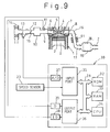
- Fig. 9 schematically illustrates the exhaust gas purification device of the present embodiment.
- the reference numerals in Fig. 9 which are same as those in Fig. 1 represent similar elements as those in Fig. 1.
- the device shown in Fig. 9 has an arrangement generally similar to the device in the embodiment in Fig. 1, except that cooling fins 91 are provided on the outer surface of the exhaust gas passage (exhaust pipe) 17.
- the total surface area of the fins 91 is set large enough to lower the exhaust gas temperature flowing through the exhaust pipe to a level lower than the predetermined temperature TH 0 explained in the previous embodiment even at the highest possible exhaust gas temperature.
- the exhaust gas temperature in the lean air-fuel ratio operation of the engine is lower than the exhaust gas temperature in the stoichiometric or rich air-fuel ratio operation of the engine.
- the cooling fins are further provided to keep the exhaust gas temperature during the lean air-fuel ratio operation lower than the predetermined temperature TH 0 , the temperature of the NO X absorbent 18 is always kept lower than the predetermined temperature, at least, at the beginning of the regenerating process (i.e., when the operating air-fuel ratio of the engine is changed from a lean air-fuel ratio to a rich air-fuel ratio). Therefore, in this embodiment, the regenerating process of the NO X absorbent can be performed regardless of the load conditions of the engine and, thereby, the saturation of the NO X absorbent with NO X is effectively prevented from occurring.
- an expansion type muffler may be provided on the exhaust pipe upstream of the NO X absorbent 18 to lower the exhaust gas temperature.
- the exhaust gas temperature is lowered due to the expansion of the exhaust gas.
- the expansion type muffler has relatively large heat capacity, the exhaust gas temperature flowing into the NO X absorbent 18 is maintained at nearly constant even when the exhaust gas temperature at the engine outlet varies if the expansion type muffler is used. Therefore, the temperature of the NO X absorbent is securely maintained lower than the predetermined temperature.
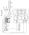
- Fig. 10 shows an embodiment of the exhaust gas purification device in which the present invention is applied to an engine operated at a slightly rich air-fuel ratio (such as, at an air excess ratio of about 0.95).
- reference numeral 101 designates an internal combustion engine operated at a slightly rich air-fuel ratio
- 117 designates an exhaust pipe of the engine 101.
- Other elements designated by same reference numbers as those in Fig. 1 are the same elements as those in Fig. 1.
- a three-way reducing and oxidizing catalyst 121, oxidizing catalyst 122 and a NO X absorbent 118 are disposed in this order from the upstream side of the exhaust pipe.
- the NO X absorbent 118 is same type as that of the previous embodiments.
- a secondary air supply unit 123 is provided in this embodiment.
- the secondary air supply unit 123 includes an air source 123a such as an air pump and a shut off/control valve 123b to supply a secondary air to the exhaust pipe 117 at the portion between the three-way reducing and oxidizing catalyst 121 and the oxidizing catalyst 122.
- the engine 101 in this embodiment is operated at a slightly rich air fuel ratio. Therefore, the exhaust gas from the engine contains a relatively small amount of NO X components and a relatively large amount of unburned HC, CO components.
- the three-way reducing and oxidizing catalyst 121 is capable of removing substantially all the NO X in the exhaust gas but it converts a small portion of NO X in the exhaust gas into NH 3 .
- the exhaust gas flowing out from the three-way reducing and oxidizing catalyst 121 includes a very small amount of NH 3 and a relatively large amount of HC and CO.
- the secondary air supply unit 123 supplies air to this exhaust gas to make the air-fuel ratio of this exhaust gas lean.
- the exhaust gas flowing into the oxidizing catalyst 122 has a lean air-fuel ratio.
- this lean air-fuel ratio exhaust gas flows through the oxidizing catalyst 122, the unburned HC, CO components in the exhaust gas are oxidized and removed by the catalyst 122 and, at the same time, the NH 3 in the exhaust gas is also oxidized by catalyst 122 to form NO X .
- the exhaust gas flowing into the NO X absorbent 118 has a lean air-fuel ratio and contains a small amount of NO X components, but the exhaust gas does not contain HC and CO components. Since this small amount of the NO X in the exhaust gas is absorbed by the NO X absorbent, the exhaust gas downstream of the NO X absorbent 118 is substantially free from HC, CO, NO X and NH 3 .
- the regenerating process of the NO X absorbent 118 in this embodiment is carried out by stopping the supply of the secondary air from the unit 123.
- the air-fuel ratio of the exhaust gas flowing into the oxidizing catalyst 122 becomes rich, and the oxidation of the HC, CO and NH 3 components by the oxidizing catalyst does not occur. Therefore, an exhaust gas having same components as the exhaust gas at the outlet of the three-way reducing and oxidizing catalyst 121, i.e., an exhaust gas of a rich air-fuel ratio containing a small amount of NH 3 and a relatively large amount of HC, CO flows into the NO X absorbent 118.
- the NO X absorbed in the NO X absorbent 118 is released from the absorbent in the rich atmosphere, and reduced by the HC, CO in the exhaust gas.
- the regeneration of the NO X absorbent 118 in this case, by stopping the supply of the secondary air, is carried out only when the temperature of the NO X absorbent 118 is lower than the predetermined temperature TH 0 to prevent the outflow of NO X at the beginning of the regeneration process.
- the intervals required for the regeneration of the NO X absorbent 118 are quite long compared to those of the previous embodiments. Therefore, even if the regeneration of the NO X absorbent is not performed for a long time, the saturation of the NO X absorbent with NO X does not occur in this embodiment.
- the cooling fins similar to Fig. 9, or the muffler may be provided on the exhaust pipe between the oxidizing catalyst 121 and the NO X absorbent 118 to keep the temperature of the NO X absorbent 118 lower than the predetermined temperature at the beginning of the regenerating process.
- the arrangement of the device in this embodiment is the same as that of Fig. 1.
- the regenerating process in this embodiment is carried out even when the temperature of the NO X absorbent is higher than the predetermined temperature. If the regenerating process is carried out frequently even when the temperature is high, the amount of NO X outflow becomes large. Therefore, the regeneration of the NO X absorbent in this embodiment is controlled so that the regenerating process is carried out less frequently when the temperature is high.
- the frequency of the regeneration of the NO X absorbent is reduced by the following controls:
- the amount of the NO X accumulated in the NO X absorbent is always maintained at a relatively small value during a low temperature operation of the NO X absorbent. Therefore, when a high temperature operation of the NO X absorbent starts, a relatively large capacity of the NO X absorbent for absorbing NO X is always preserved. This lowers the possibility of the regenerating process being carried out during a high temperature operation of the NO X absorbent of a short period.
- the regenerating process is not performed until the amount of the NO X accumulated in the NO X absorbent increases to a relatively large value by the above control (2). Therefore, the possibility of the regenerating process being performed during the high temperature operation is further lowered in addition to the above.
- the NO X absorbent can start the absorbing operation of NO X with a small amount of NO X accumulated in the NO X absorbent.
- the frequency of the regenerating process of the NO X absorbent are lowered by the above controls (1) to (3), when the temperature of the NO X absorbent is high, the probability that the regenerating process is carried out during the high temperature operation, i.e., the probability that the outflow of NO X occurs, becomes small, thereby the worsening of the NO X emission can be suppressed as a whole. Further, according to the present embodiment, the regenerating process of the NO X absorbent is carried out even during the high temperature operation if the amount of the NO X accumulated in the NO X absorbent substantially increases. Therefore, the worsening of the NO X emission due to the NO X absorbent being saturated with NO X does not occur even though the high temperature operation of the NO X absorbent continues for a long time.
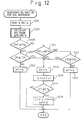
- Fig. 12 shows a flowchart of the regenerating process in the present embodiment. This routine is processed at regular intervals by the control circuit 30.
- steps 1201 and 1203 the present temperature THC of the NO X absorbent is calculated. Steps 1201 and 1203 are the same as steps 801 and 803 in Fig. 8, and a detailed explanation is omitted here.
- step 1205 it is determined whether the temperature THC of the NO X absorbent is higher than or equal to a predetermined value TH 0 .
- the value TH 0 in this embodiment is set at the same level as that in Fig. 8, step 807.
- step 1205 determines whether the high temperature operation of the NO X absorbent is being carried out at step 1205 (i.e., THC ⁇ TH 0 ).
- the routine then proceeds to step 1207 which determines whether the amount CR of the NO X accumulated in the NO X absorbent has reached a predetermined value CR 1 .
- the value CR 1 is set at a relatively large value in this embodiment (for example, about 70% of the amount of NO X when the NO X absorbent is saturated with NO X ). If CR ⁇ CR 1 at step 1207, the value of the flag XF is reset to 0 at step 1209, and the routine terminates immediately.
- the function of the regeneration flag XF is the same as that of Fig. 8 also in this embodiment.
- steps 1213 to 1219 are processed in this embodiment.
- the regenerating process similar to those at steps 809 through 815 are carried out, i.e., in this embodiment, even when the temperature of NO X absorbent is high (THC ⁇ TH 0 ), the regenerating process is carried out if the amount of the NO X accumulated in the NO X absorbent reaches a relatively large value (CR ⁇ CR 1 ).
- THC ⁇ TH 0 at step 1205 i.e., if the low temperature operation of the NO X absorbent is being carried out
- the amount of the NO X accumulated in the NO X absorbent is lowered immediately after the high temperature operation of the NO X absorbent is terminated, and even if the high temperature operation of the NO X absorbent is resumed shortly, the NO X absorbent can start the absorbing operation of NO X with a small amount of NO X accumulated in the absorbent.
- step 1211 determines whether the present amount CR of the NO X in the absorbent is larger than or equal to a second predetermined value CR 2 .
- the value of CR 2 is set at smaller than the value of CR 1 , and in this embodiment, CR 2 is set at, for example, about 10% of the amount of NO X when the NO X absorbent is saturated with NO X .
- the regenerating process of the NO X absorbent is performed when the amount CR of NO X in the absorbent reaches a relatively small value (CR 2 ) during the low temperature operation of the NO X absorbent. Therefore, the amount of the NO X accumulated in the NO X absorbent is always kept small during the low temperature operation of the NO X absorbent.
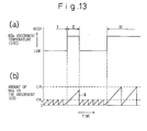
- Fig. 13 is a timing diagram illustrating the regenerating process according to the flowchart in Fig. 12.
- the curve (a) in Fig. 13 represents the change in the temperature THC of the NO X absorbent
- the curve (b) in Fig. 13 represents the amount CR of the NO X accumulated in the NO X absorbent when the temperature of the NO X absorbent changes as shown by the curve (a).
- the regenerating process of the NO X absorbent is repeated at short intervals every time when the amount CR of the NO X in the absorbent reaches a relatively small value CR 2 , and the amount CR becomes almost 0 after every regenerating process (Fig. 13, period I).
- the amount CR of the NO X accumulated in the NO X absorbent is always kept lower than CR 2 .
- the regenerating process of the NO X absorbent is not performed until the amount CR reaches a relatively large value CR 1 (Fig. 13, period II).
- the amount CR of the NO X accumulated in the NO X absorbent is CR 2 at maximum when the high temperature operation starts. Therefore, the NO x absorbent is capable of absorbing the amount of NO X at least corresponding (CR 1 - CR 2 ) before the regenerating process is carried out during the high temperature operation.
- the regenerating process is carried out immediately in this embodiment (Fig. 13, portion III). Therefore, the amount CR is reduced to 0 as soon as the high temperature operation terminates, thereby the NO X absorbent resumes its maximum capability for absorbing NO X . If the high temperature operation continues longer (Fig. 13, period IV), the regenerating process of the NO X absorbent is performed when the amount CR reaches a relatively large value CR 1 . Therefore, even when the high temperature operation continues for a long time, the saturation of the NO X absorbent with NO X does not occur.
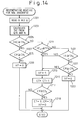
- Fig. 14 shows another embodiment of the flowchart of regenerating process of the NO X absorbent according to the present invention.
- the flowchart in Fig. 14 is identical to the flowchart in Fig. 12, except that step 1401 is added in Fig. 14 between steps 1211 and 1221.
- the routine determines at step 1401 whether the degree of opening TA of the throttle valve is larger than or equal to a predetermined value TA 0 If TA ⁇ TA 0 at step 1401, then the routine proceeds to step 1213 to perform the regenerating process regardless of the amount CR. On the other hand, if TA ⁇ TA 0 at step 1401, the routine proceeds to step 1221. In this case the regenerating process is carried out only when the amount CR reaches the value CR 1 .
- the temperature of the NO X absorbent in the immediate future is estimated based on the change in the degree of opening TA of the throttle valve. Namely, since the degree of opening TA of the throttle valve represents the engine load, if the present value of TA is large (i.e., if the present engine load is high), the exhaust gas temperature (i.e., the temperature of the NO X absorbent) will rise in a short time even if the present temperature of the NO X absorbent is low.
- the regenerating process is performed regardless of the amount CR if the degree of opening TA of the throttle valve becomes larger than or equal to the value TA 0 to prepare for a possible high temperature operation by reducing the amount of the NO X accumulated in the NO X absorbent. Therefore, whenever the high temperature operation starts, the NO X absorbent in this embodiment can maintain a large capacity for absorbing NO X in the exhaust gas.
- the degree of opening TA of the throttle valve is used for estimating the temperature of the NO X absorbent in the future, other operating parameters of the engine, such as an intake manifold pressure, may be used for estimating the temperature of the NO X absorbent in the future.
- the outflow of NO X at the beginning of the regenerating process of the NO X absorbent in the high temperature operation can be suppressed, to thereby minimize the emission of NO X to the atmosphere.
Claims (5)
- Abgasreinigungsvorrichtung für eine Brennkraftmaschine mit:einem NOx-Absorptionsmittel, das in einem Abgaskanal einer Brennkraftmaschine angeordnet ist, wobei das NOx-Absorptionsmittel NOx-Bestandteile in dem Abgas des Motors absorbiert, wenn das Luft-/Kraftstoffverhältnis des in das NOx-Absorptionsmittel einströmenden Abgases mager ist und die absorbierten NOx-Bestandteile freigibt, wenn die Sauerstoffkonzentration in dem Abgas niedriger wird;einer Erfassungseinrichtung zum Erfassen der Menge der in dem NOx-Absorptionsmittel akkumulierten NOx;einer Regenerationseinrichtung zum Veranlassen, dass das Luft-/Kraftstoffverhältnis des in das NOx-Absorptionsmittel einströmenden Abgases fett oder stoichiometrisch wird, und dadurch veranlassen, dass die in dem NOx-Absorptionsmittel akkumulierten NOx aus dem NOx-Absorptionsmittel freigegeben und reduziert werden;einer Aktivierungseinrichtung zum Aktivieren der Regenerationseinrichtung bei einer Zeitgebung, die durch die Menge der in dem Absorptionsmittel akkumulierten NOx nur dann ermittelt wird, wenn die Temperatur des NOx-Absorptionsmittels niedriger ist als eine vorgegebene Temperatur.
- Abgasreinigungsvorrichtung für eine Brennkraftmaschine mit:einem NOx-Absorptionsmittel, das in dem Abgaskanal einer Brennkraftmaschine angeordnet ist, wobei das NOx-Absorptionsmittel NOx-Bestandteile in dem Abgas des Motors absorbiert, wenn das Luft-/Kraftstoffverhältnis des in das NOx-Absorptionsmittel einströmenden Abgases mager ist und die absorbierten NOx-Bestandteile freigibt, wenn die Sauerstoffkonzentration in dem Abgas niedriger wird;einer Erfassungseinrichtung zum Erfassen der Menge der in dem NOx-Absorptionsmittel akkumulierten NOx;einer Regenerationseinrichtung zum Veranlassen, dass das Luft-/Kraftstoffverhältnis des in das NOx-Absorptionsmittel einströmenden Abgases fett oder stöchiometrisch wird, und dadurch veranlassen, dass die in dem NOx-Absorptionsmittel akkumulierten NOx aus dem NOx-Absorptionsmittel freigegeben und reduziert werden;einer Aktivierungseinrichtung zum Aktivieren der Regenerationseinrichtung bei einer Zeitgebung, die durch die Menge der in dem Absorptionsmittel akkumulierten NOx ermittelt wird, wenn die Temperatur des NOx-Absorptionsmittels niedriger ist als eine vorgegebene Temperatur, wobei, wenn die Temperatur des NOx-Absorptionsmittels höher ist als die vorgegebene Temperatur, die Regenerationseinrichtung aktiviert wird, wenn die Menge CR der in dem NOx-Absorptionsmittel akkumulierten NOx einen vorgegebenen Wert CR1 erreicht.
- Abgasreinigungsvorrichtung nach Anspruch 1 oder 2, wobei eine Regenerationsregeleinrichtung zum Regeln der Aktivierungseinrichtung eine Temperaturregeleinrichtung zum Halten der Temperatur des NOx-Absorptionsmittels aufweist, die niedriger ist als die vorgegebene Temperatur, zumindest dann, wenn die Regenetionseinrichtung veranlasst, dass das Luft/Kraftstoffverhältnis des in das NOx-Absorptionsmittel einströmenden Abgases fett oder stöchiometrisch wird.
- Abgasreinigungsvorrichtung nach Anspruch 1 oder 2, wobei eine Regenerationszeitgebungsregeleinrichtung zum Regeln der Aktivierungseinrichtung vorgesehen ist, die die Zeitgebung der Aktivierung der Regenerationseinrichtung verzögert, wenn die Temperatur des NOx-Absorptionsmittels hoch wird.
- Abgasreinigungsvorrichtung nach Anspruch 4, wobei die Aktivierungseinrichtung eine NOx-Mengenerfassungseinrichtung zum Erfassen der Menge der in dem NOx-Absorptionsmittel akkumulierten NOx aufweist und die Regenerationseinrichtung aktiviert, wenn die Menge der in dem NOx-Absorptionsmittel akkumulierten NOx größer wird als ein vorgegebener eingerichteter Wert, und wobei die Regenerationszeitgebungsregeleinrichtung den eingerichteten Wert erhöht, wenn die Temperatur des NOx-Absorptionsmittels hoch wird.
Applications Claiming Priority (6)
| Application Number | Priority Date | Filing Date | Title |
|---|---|---|---|
| JP29166294 | 1994-11-25 | ||
| JP291662/94 | 1994-11-25 | ||
| JP29166294 | 1994-11-25 | ||
| JP263019/95 | 1995-10-11 | ||
| JP26301995A JP3440654B2 (ja) | 1994-11-25 | 1995-10-11 | 排気浄化装置 |
| JP26301995 | 1995-10-11 |
Publications (3)
| Publication Number | Publication Date |
|---|---|
| EP0713959A2 EP0713959A2 (de) | 1996-05-29 |
| EP0713959A3 EP0713959A3 (de) | 1996-07-03 |
| EP0713959B1 true EP0713959B1 (de) | 2000-03-22 |
Family
ID=26545824
Family Applications (1)
| Application Number | Title | Priority Date | Filing Date |
|---|---|---|---|
| EP95118457A Expired - Lifetime EP0713959B1 (de) | 1994-11-25 | 1995-11-23 | Abgasreinigungsvorrichtung für eine Brennkraftmaschine |
Country Status (4)
| Country | Link |
|---|---|
| US (1) | US5740669A (de) |
| EP (1) | EP0713959B1 (de) |
| JP (1) | JP3440654B2 (de) |
| DE (1) | DE69515803T2 (de) |
Families Citing this family (108)
| Publication number | Priority date | Publication date | Assignee | Title |
|---|---|---|---|---|
| KR100287049B1 (ko) * | 1995-10-30 | 2001-05-02 | 와다 아끼히로 | 내연기관용 배기 가스 정화 장치 |
| US6133185A (en) * | 1995-11-09 | 2000-10-17 | Toyota Jidosha Kabushiki Kaisha | Exhaust gas purifying catalyst |
| US6345496B1 (en) | 1995-11-09 | 2002-02-12 | Toyota Jidosha Kabushiki Kaisha | Method and device for purifying exhaust gas of an engine |
| ES2151680T3 (es) * | 1995-11-17 | 2001-01-01 | Toyota Motor Co Ltd | Procedimiento y dispositivo para purificar los gases de escape de un motor. |
| WO1997019261A1 (fr) * | 1995-11-17 | 1997-05-29 | Toyota Jidosha Kabushiki Kaisha | Dispositif de reglage des emissions d'echappement pour moteurs a combustion interne |
| JP3702544B2 (ja) * | 1996-03-22 | 2005-10-05 | トヨタ自動車株式会社 | 内燃機関の排気浄化装置 |
| JP3713831B2 (ja) * | 1996-04-19 | 2005-11-09 | トヨタ自動車株式会社 | 内燃機関の排気浄化装置 |
| DE69730539T2 (de) | 1996-06-10 | 2005-06-23 | Hitachi, Ltd. | Abgasreinigungsanlage einer Brennkraftmaschine und Katalysator zum Reinigen des Abgases einer Brennkraftmaschine |
| AU742434B2 (en) * | 1996-06-10 | 2002-01-03 | Hitachi Limited | Exhaust gas purification apparatus of internal combustion engine and catalyst for purifying exhaust gas of internal combustion engine |
| JP2871615B2 (ja) * | 1996-09-09 | 1999-03-17 | トヨタ自動車株式会社 | 内燃機関の排気浄化装置 |
| JP3965711B2 (ja) | 1996-10-25 | 2007-08-29 | 株式会社日立製作所 | 窒素酸化物の浄化触媒及び浄化方法 |
| JP3645704B2 (ja) * | 1997-03-04 | 2005-05-11 | トヨタ自動車株式会社 | 内燃機関の排気浄化装置 |
| US5894725A (en) * | 1997-03-27 | 1999-04-20 | Ford Global Technologies, Inc. | Method and apparatus for maintaining catalyst efficiency of a NOx trap |
| JP4034375B2 (ja) * | 1997-04-03 | 2008-01-16 | トヨタ自動車株式会社 | 内燃機関の排気浄化装置 |
| DE19716275C1 (de) * | 1997-04-18 | 1998-09-24 | Volkswagen Ag | Verfahren zur Stickoxidreduzierung im Abgas einer Brennkraftmaschine |
| JP3456408B2 (ja) * | 1997-05-12 | 2003-10-14 | トヨタ自動車株式会社 | 内燃機関の排気浄化装置 |
| DE19721440A1 (de) * | 1997-05-21 | 1998-11-26 | Degussa | Verfahren zur Reinigung eines mageren Abgases und Katalysatorsystem hierfür |
| JP3282660B2 (ja) * | 1997-06-16 | 2002-05-20 | 本田技研工業株式会社 | 内燃機関の排気ガス浄化装置 |
| JP3123474B2 (ja) * | 1997-07-28 | 2001-01-09 | トヨタ自動車株式会社 | 内燃機関の排気浄化装置 |
| JP3264226B2 (ja) * | 1997-08-25 | 2002-03-11 | トヨタ自動車株式会社 | 内燃機関の排気浄化装置 |
| US5983627A (en) * | 1997-09-02 | 1999-11-16 | Ford Global Technologies, Inc. | Closed loop control for desulfating a NOx trap |
| DE19739848A1 (de) * | 1997-09-11 | 1999-03-18 | Bosch Gmbh Robert | Brennkraftmaschine insbesondere für ein Kraftfahrzeug |
| US6148612A (en) * | 1997-10-13 | 2000-11-21 | Denso Corporation | Engine exhaust gas control system having NOx catalyst |
| US6021638A (en) * | 1997-11-24 | 2000-02-08 | Engelhard Corporation | Engine management strategy to improve the ability of a catalyst to withstand severe operating enviroments |
| FR2772428B1 (fr) * | 1997-12-12 | 2000-02-18 | Renault | Procede de commande de purge d'un pot catalytique de traitement des gaz d'echappement d'un moteur a combustion interne |
| EP0940570B1 (de) * | 1998-01-09 | 2001-08-22 | Ford Global Technologies, Inc. | Verfahren zur Regeneration einer Stickoxidfalle im Abgasesystem eines Verbrennungsmotors unter Berücksichtigung des Abgasmassenstromes |
| JP3531867B2 (ja) * | 1998-11-09 | 2004-05-31 | シーメンス アクチエンゲゼルシヤフト | 空気過剰で作動する内燃機関の未浄化(ロー)NOx濃度を適合するための方法 |
| US6182444B1 (en) | 1999-06-07 | 2001-02-06 | Ford Global Technologies, Inc. | Emission control system |
| US6244044B1 (en) * | 1999-09-20 | 2001-06-12 | Southwest Research Institute | Method for reducing cold-start hydrocarbon emissions in a gasoline, natural gas, or propane fueled engine |
| KR100314172B1 (ko) * | 1999-10-06 | 2001-11-15 | 이계안 | 린번 엔진의 배기가스 정화용 산화바륨 촉매의 활성화 장치 |
| US6632764B2 (en) * | 2000-01-19 | 2003-10-14 | Volkswagen Ag | Method for controlling the regeneration of an NOx storage converter |
| JP3633421B2 (ja) * | 2000-02-25 | 2005-03-30 | トヨタ自動車株式会社 | 動力出力装置 |
| US6629453B1 (en) | 2000-03-17 | 2003-10-07 | Ford Global Technologies, Llc | Method and apparatus for measuring the performance of an emissions control device |
| US6308515B1 (en) | 2000-03-17 | 2001-10-30 | Ford Global Technologies, Inc. | Method and apparatus for accessing ability of lean NOx trap to store exhaust gas constituent |
| US6308697B1 (en) | 2000-03-17 | 2001-10-30 | Ford Global Technologies, Inc. | Method for improved air-fuel ratio control in engines |
| US6487849B1 (en) | 2000-03-17 | 2002-12-03 | Ford Global Technologies, Inc. | Method and apparatus for controlling lean-burn engine based upon predicted performance impact and trap efficiency |
| US6434930B1 (en) | 2000-03-17 | 2002-08-20 | Ford Global Technologies, Inc. | Method and apparatus for controlling lean operation of an internal combustion engine |
| US6481199B1 (en) | 2000-03-17 | 2002-11-19 | Ford Global Technologies, Inc. | Control for improved vehicle performance |
| US6360530B1 (en) | 2000-03-17 | 2002-03-26 | Ford Global Technologies, Inc. | Method and apparatus for measuring lean-burn engine emissions |
| US6374597B1 (en) | 2000-03-17 | 2002-04-23 | Ford Global Technologies, Inc. | Method and apparatus for accessing ability of lean NOx trap to store exhaust gas constituent |
| US6499293B1 (en) | 2000-03-17 | 2002-12-31 | Ford Global Technologies, Inc. | Method and system for reducing NOx tailpipe emissions of a lean-burn internal combustion engine |
| US6438944B1 (en) | 2000-03-17 | 2002-08-27 | Ford Global Technologies, Inc. | Method and apparatus for optimizing purge fuel for purging emissions control device |
| US6843051B1 (en) | 2000-03-17 | 2005-01-18 | Ford Global Technologies, Llc | Method and apparatus for controlling lean-burn engine to purge trap of stored NOx |
| US6487850B1 (en) | 2000-03-17 | 2002-12-03 | Ford Global Technologies, Inc. | Method for improved engine control |
| US6594989B1 (en) | 2000-03-17 | 2003-07-22 | Ford Global Technologies, Llc | Method and apparatus for enhancing fuel economy of a lean burn internal combustion engine |
| US6708483B1 (en) | 2000-03-17 | 2004-03-23 | Ford Global Technologies, Llc | Method and apparatus for controlling lean-burn engine based upon predicted performance impact |
| US6477832B1 (en) | 2000-03-17 | 2002-11-12 | Ford Global Technologies, Inc. | Method for improved performance of a vehicle having an internal combustion engine |
| US6810659B1 (en) | 2000-03-17 | 2004-11-02 | Ford Global Technologies, Llc | Method for determining emission control system operability |
| US6427437B1 (en) | 2000-03-17 | 2002-08-06 | Ford Global Technologies, Inc. | Method for improved performance of an engine emission control system |
| US6860100B1 (en) * | 2000-03-17 | 2005-03-01 | Ford Global Technologies, Llc | Degradation detection method for an engine having a NOx sensor |
| US6327847B1 (en) | 2000-03-17 | 2001-12-11 | Ford Global Technologies, Inc. | Method for improved performance of a vehicle |
| US6539704B1 (en) | 2000-03-17 | 2003-04-01 | Ford Global Technologies, Inc. | Method for improved vehicle performance |
| US6370868B1 (en) * | 2000-04-04 | 2002-04-16 | Ford Global Technologies, Inc. | Method and system for purge cycle management of a lean NOx trap |
| DE10017940C2 (de) * | 2000-04-11 | 2003-01-23 | Omg Ag & Co Kg | Verfahren zur Überprüfung der Funktionstüchtigkeit eines Stickoxid-Speicherkatalysators |
| US6389803B1 (en) | 2000-08-02 | 2002-05-21 | Ford Global Technologies, Inc. | Emission control for improved vehicle performance |
| US6691507B1 (en) | 2000-10-16 | 2004-02-17 | Ford Global Technologies, Llc | Closed-loop temperature control for an emission control device |
| US6490860B1 (en) | 2001-06-19 | 2002-12-10 | Ford Global Technologies, Inc. | Open-loop method and system for controlling the storage and release cycles of an emission control device |
| US6487853B1 (en) | 2001-06-19 | 2002-12-03 | Ford Global Technologies. Inc. | Method and system for reducing lean-burn vehicle emissions using a downstream reductant sensor |
| US6502387B1 (en) | 2001-06-19 | 2003-01-07 | Ford Global Technologies, Inc. | Method and system for controlling storage and release of exhaust gas constituents in an emission control device |
| US6453666B1 (en) | 2001-06-19 | 2002-09-24 | Ford Global Technologies, Inc. | Method and system for reducing vehicle tailpipe emissions when operating lean |
| US6553754B2 (en) | 2001-06-19 | 2003-04-29 | Ford Global Technologies, Inc. | Method and system for controlling an emission control device based on depletion of device storage capacity |
| US6650991B2 (en) | 2001-06-19 | 2003-11-18 | Ford Global Technologies, Llc | Closed-loop method and system for purging a vehicle emission control |
| US6615577B2 (en) | 2001-06-19 | 2003-09-09 | Ford Global Technologies, Llc | Method and system for controlling a regeneration cycle of an emission control device |
| US6604504B2 (en) | 2001-06-19 | 2003-08-12 | Ford Global Technologies, Llc | Method and system for transitioning between lean and stoichiometric operation of a lean-burn engine |
| US6694244B2 (en) | 2001-06-19 | 2004-02-17 | Ford Global Technologies, Llc | Method for quantifying oxygen stored in a vehicle emission control device |
| US6546718B2 (en) | 2001-06-19 | 2003-04-15 | Ford Global Technologies, Inc. | Method and system for reducing vehicle emissions using a sensor downstream of an emission control device |
| US6467259B1 (en) | 2001-06-19 | 2002-10-22 | Ford Global Technologies, Inc. | Method and system for operating dual-exhaust engine |
| US6463733B1 (en) | 2001-06-19 | 2002-10-15 | Ford Global Technologies, Inc. | Method and system for optimizing open-loop fill and purge times for an emission control device |
| US6539706B2 (en) | 2001-06-19 | 2003-04-01 | Ford Global Technologies, Inc. | Method and system for preconditioning an emission control device for operation about stoichiometry |
| US6691020B2 (en) | 2001-06-19 | 2004-02-10 | Ford Global Technologies, Llc | Method and system for optimizing purge of exhaust gas constituent stored in an emission control device |
| JP3815289B2 (ja) * | 2001-10-19 | 2006-08-30 | トヨタ自動車株式会社 | 内燃機関の排気浄化装置 |
| JP3800065B2 (ja) * | 2001-10-26 | 2006-07-19 | トヨタ自動車株式会社 | 内燃機関の排気浄化装置 |
| US6574953B1 (en) * | 2001-11-29 | 2003-06-10 | Ford Global Technologies, Llc | NOx purge air/fuel ratio selection |
| US6732506B2 (en) * | 2002-04-03 | 2004-05-11 | General Motors Corporation | Cylinder deactivation system and NOx trap regeneration |
| US6769398B2 (en) * | 2002-06-04 | 2004-08-03 | Ford Global Technologies, Llc | Idle speed control for lean burn engine with variable-displacement-like characteristic |
| US6725830B2 (en) | 2002-06-04 | 2004-04-27 | Ford Global Technologies, Llc | Method for split ignition timing for idle speed control of an engine |
| US6868827B2 (en) | 2002-06-04 | 2005-03-22 | Ford Global Technologies, Llc | Method for controlling transitions between operating modes of an engine for rapid heating of an emission control device |
| US6568177B1 (en) | 2002-06-04 | 2003-05-27 | Ford Global Technologies, Llc | Method for rapid catalyst heating |
| US6745747B2 (en) | 2002-06-04 | 2004-06-08 | Ford Global Technologies, Llc | Method for air-fuel ratio control of a lean burn engine |
| US7111450B2 (en) * | 2002-06-04 | 2006-09-26 | Ford Global Technologies, Llc | Method for controlling the temperature of an emission control device |
| US6735938B2 (en) | 2002-06-04 | 2004-05-18 | Ford Global Technologies, Llc | Method to control transitions between modes of operation of an engine |
| US6715462B2 (en) | 2002-06-04 | 2004-04-06 | Ford Global Technologies, Llc | Method to control fuel vapor purging |
| US6758185B2 (en) | 2002-06-04 | 2004-07-06 | Ford Global Technologies, Llc | Method to improve fuel economy in lean burn engines with variable-displacement-like characteristics |
| US7032572B2 (en) * | 2002-06-04 | 2006-04-25 | Ford Global Technologies, Llc | Method for controlling an engine to obtain rapid catalyst heating |
| US6736120B2 (en) * | 2002-06-04 | 2004-05-18 | Ford Global Technologies, Llc | Method and system of adaptive learning for engine exhaust gas sensors |
| US6925982B2 (en) | 2002-06-04 | 2005-08-09 | Ford Global Technologies, Llc | Overall scheduling of a lean burn engine system |
| US7168239B2 (en) * | 2002-06-04 | 2007-01-30 | Ford Global Technologies, Llc | Method and system for rapid heating of an emission control device |
| US6736121B2 (en) | 2002-06-04 | 2004-05-18 | Ford Global Technologies, Llc | Method for air-fuel ratio sensor diagnosis |
| JP4385593B2 (ja) | 2002-12-10 | 2009-12-16 | トヨタ自動車株式会社 | 内燃機関の排気浄化装置 |
| US6817171B2 (en) * | 2003-01-17 | 2004-11-16 | Daimlerchrysler Corporation | System and method for predicting concentration of undesirable exhaust emissions from an engine |
| US6945033B2 (en) * | 2003-06-26 | 2005-09-20 | Ford Global Technologies, Llc | Catalyst preconditioning method and system |
| DE102004021373A1 (de) * | 2004-04-30 | 2005-11-17 | Robert Bosch Gmbh | Verfahren zum Betreiben einer Abgasbehandlungsvorrichtung |
| JP2006104966A (ja) * | 2004-10-01 | 2006-04-20 | Hitachi Ltd | 内燃機関の排ガス浄化装置及び排ガス浄化方法 |
| US7565799B2 (en) * | 2005-02-09 | 2009-07-28 | Gm Global Technology Operations, Inc. | Controlling lean NOx trap (LNT) catalyst performance |
| JP4572709B2 (ja) * | 2005-03-18 | 2010-11-04 | トヨタ自動車株式会社 | 内燃機関の排気浄化システム |
| DE602005019857D1 (de) * | 2005-05-03 | 2010-04-22 | Fiat Ricerche | Verfahren zur Aktivierung der Regeneration eines NOx-Adsorber |
| DE102006053804B4 (de) * | 2006-11-15 | 2018-04-19 | Robert Bosch Gmbh | Flanschverbindung |
| US7810315B2 (en) * | 2007-02-20 | 2010-10-12 | Eaton Corporation | LNT regeneration strategy to reduce NOx spike |
| US20080196398A1 (en) * | 2007-02-20 | 2008-08-21 | Eaton Corporation | HC mitigation to reduce NOx spike |
| US20080314022A1 (en) * | 2007-06-19 | 2008-12-25 | Eaton Corporation | Strategy for scheduling LNT regeneration |
| US7980064B2 (en) * | 2007-06-19 | 2011-07-19 | Eaton Corporation | Algorithm incorporating driving conditions into LNT regeneration scheduling |
| DE102007046353B3 (de) * | 2007-09-27 | 2009-04-16 | Continental Automotive Gmbh | Regenerationsverfahren für einen Speicherkatalysator |
| JP4436397B2 (ja) * | 2007-10-01 | 2010-03-24 | 本田技研工業株式会社 | 内燃機関の排ガス浄化装置 |
| FR2927119B1 (fr) * | 2008-02-04 | 2010-03-05 | Renault Sas | Procede de gestion d'un dispositif de post-traitement des gaz d'echappement d'un moteur, incluant un mode basse frequence et un mode haute frequence d'alternance des phases de stockage et de purge. |
| US8857159B2 (en) * | 2009-11-25 | 2014-10-14 | Gm Global Technology Operations, Inc. | Systems and methods for reducing NOx breakthrough |
| US8578704B2 (en) * | 2010-04-28 | 2013-11-12 | Tecogen, Inc. | Assembly and method for reducing nitrogen oxides, carbon monoxide and hydrocarbons in exhausts of internal combustion engines |
| DE102016222012B4 (de) * | 2015-12-18 | 2022-09-29 | Ford Global Technologies, Llc | Verfahren zum Steuern eines NOx-Speicher-Katalysators |
| US20200291877A1 (en) * | 2019-03-12 | 2020-09-17 | GM Global Technology Operations LLC | Aggressive thermal heating target strategy based on nox estimated feedback |
Citations (1)
| Publication number | Priority date | Publication date | Assignee | Title |
|---|---|---|---|---|
| EP0503882A1 (de) * | 1991-03-13 | 1992-09-16 | Toyota Jidosha Kabushiki Kaisha | Vorrichtung zur Reinigung von Abgasen eines Verbrennungsmotors |
Family Cites Families (10)
| Publication number | Priority date | Publication date | Assignee | Title |
|---|---|---|---|---|
| US3819334A (en) * | 1970-10-27 | 1974-06-25 | Mitsui Mining & Smelting Co | Catalytic reaction apparatus for purifying waste gases containing carbon monoxide |
| JP3375645B2 (ja) * | 1991-05-14 | 2003-02-10 | 株式会社日立製作所 | 内燃機関の制御装置 |
| WO1993007363A1 (fr) * | 1991-10-03 | 1993-04-15 | Toyota Jidosha Kabushiki Kaisha | Dispositif pour purifier les gaz d'echappement d'un moteur a combustion interne |
| WO1993025806A1 (en) * | 1992-06-12 | 1993-12-23 | Toyota Jidosha Kabushiki Kaisha | Exhaust emission control system for internal combustion engine |
| JP2722951B2 (ja) * | 1992-06-25 | 1998-03-09 | トヨタ自動車株式会社 | 内燃機関の排気浄化装置 |
| JP2605586B2 (ja) * | 1992-07-24 | 1997-04-30 | トヨタ自動車株式会社 | 内燃機関の排気浄化装置 |
| JP2689829B2 (ja) * | 1992-09-10 | 1997-12-10 | トヨタ自動車株式会社 | 内燃機関の排気浄化装置 |
| JP2677130B2 (ja) * | 1992-09-28 | 1997-11-17 | トヨタ自動車株式会社 | 内燃機関の排気浄化装置 |
| JP2605556B2 (ja) * | 1992-10-13 | 1997-04-30 | トヨタ自動車株式会社 | 内燃機関の排気浄化装置 |
| JP3246086B2 (ja) * | 1993-06-11 | 2002-01-15 | トヨタ自動車株式会社 | 内燃機関の排気浄化装置 |
-
1995
- 1995-10-11 JP JP26301995A patent/JP3440654B2/ja not_active Expired - Fee Related
- 1995-11-16 US US08/559,107 patent/US5740669A/en not_active Expired - Lifetime
- 1995-11-23 DE DE69515803T patent/DE69515803T2/de not_active Expired - Lifetime
- 1995-11-23 EP EP95118457A patent/EP0713959B1/de not_active Expired - Lifetime
Patent Citations (1)
| Publication number | Priority date | Publication date | Assignee | Title |
|---|---|---|---|---|
| EP0503882A1 (de) * | 1991-03-13 | 1992-09-16 | Toyota Jidosha Kabushiki Kaisha | Vorrichtung zur Reinigung von Abgasen eines Verbrennungsmotors |
Also Published As
| Publication number | Publication date |
|---|---|
| EP0713959A3 (de) | 1996-07-03 |
| US5740669A (en) | 1998-04-21 |
| DE69515803D1 (de) | 2000-04-27 |
| DE69515803T2 (de) | 2000-10-12 |
| JPH08200049A (ja) | 1996-08-06 |
| EP0713959A2 (de) | 1996-05-29 |
| JP3440654B2 (ja) | 2003-08-25 |
Similar Documents
| Publication | Publication Date | Title |
|---|---|---|
| EP0713959B1 (de) | Abgasreinigungsvorrichtung für eine Brennkraftmaschine | |
| US6477834B1 (en) | Exhaust emission controlling apparatus of internal combustion engine | |
| US5448887A (en) | Exhaust gas purification device for an engine | |
| EP0598916B1 (de) | Abgasemissionssteuerungssystem für verbrennungsmotoren | |
| US5974794A (en) | Exhaust gas purification device for an internal combustion engine | |
| JP4613962B2 (ja) | 内燃機関の排気浄化装置 | |
| KR0165953B1 (ko) | 내연기관의 배기 정화 장치 | |
| US6205773B1 (en) | Exhaust gas purification device for an internal combustion engine | |
| US6345498B2 (en) | Exhaust gas purifier for internal combustion engine | |
| EP1760282B1 (de) | Abgasreiniger für einen kompressionsgezündeten verbrennungsmotor | |
| JP4304428B2 (ja) | 内燃機関の排気ガス浄化システム | |
| JPH1193744A (ja) | 内燃機関の排気浄化装置 | |
| US8136346B2 (en) | Internal combustion engine | |
| US5388403A (en) | Exhaust gas purification device for an engine | |
| KR20020033815A (ko) | 내연기관의 배기 정화장치 | |
| JP2001303937A (ja) | 内燃機関の排気浄化装置 | |
| JP3552603B2 (ja) | 内燃機関の排気浄化装置 | |
| JP3509482B2 (ja) | 内燃機関の排気浄化装置 | |
| JP3937487B2 (ja) | 内燃機関の排気浄化装置 | |
| JP3449174B2 (ja) | 内燃機関の排気浄化装置 | |
| EP1933012B1 (de) | Abgasreiniger für einen verbrennungsmotor | |
| JPH11343833A (ja) | 内燃機関の排気浄化装置 | |
| JPH1193743A (ja) | 内燃機関の排気浄化装置 | |
| JP2605579C (de) |
Legal Events
| Date | Code | Title | Description |
|---|---|---|---|
| PUAI | Public reference made under article 153(3) epc to a published international application that has entered the european phase |
Free format text: ORIGINAL CODE: 0009012 |
|
| PUAL | Search report despatched |
Free format text: ORIGINAL CODE: 0009013 |
|
| 17P | Request for examination filed |
Effective date: 19951123 |
|
| AK | Designated contracting states |
Kind code of ref document: A2 Designated state(s): DE FR GB |
|
| AK | Designated contracting states |
Kind code of ref document: A3 Designated state(s): DE FR GB |
|
| 17Q | First examination report despatched |
Effective date: 19980312 |
|
| GRAG | Despatch of communication of intention to grant |
Free format text: ORIGINAL CODE: EPIDOS AGRA |
|
| GRAG | Despatch of communication of intention to grant |
Free format text: ORIGINAL CODE: EPIDOS AGRA |
|
| GRAH | Despatch of communication of intention to grant a patent |
Free format text: ORIGINAL CODE: EPIDOS IGRA |
|
| GRAH | Despatch of communication of intention to grant a patent |
Free format text: ORIGINAL CODE: EPIDOS IGRA |
|
| GRAA | (expected) grant |
Free format text: ORIGINAL CODE: 0009210 |
|
| AK | Designated contracting states |
Kind code of ref document: B1 Designated state(s): DE FR GB |
|
| REF | Corresponds to: |
Ref document number: 69515803 Country of ref document: DE Date of ref document: 20000427 |
|
| ET | Fr: translation filed | ||
| PLBE | No opposition filed within time limit |
Free format text: ORIGINAL CODE: 0009261 |
|
| STAA | Information on the status of an ep patent application or granted ep patent |
Free format text: STATUS: NO OPPOSITION FILED WITHIN TIME LIMIT |
|
| 26N | No opposition filed | ||
| REG | Reference to a national code |
Ref country code: GB Ref legal event code: IF02 |
|
| REG | Reference to a national code |
Ref country code: GB Ref legal event code: 746 Effective date: 20130827 |
|
| REG | Reference to a national code |
Ref country code: DE Ref legal event code: R084 Ref document number: 69515803 Country of ref document: DE Effective date: 20130829 |
|
| PGFP | Annual fee paid to national office [announced via postgrant information from national office to epo] |
Ref country code: GB Payment date: 20141119 Year of fee payment: 20 Ref country code: DE Payment date: 20141118 Year of fee payment: 20 Ref country code: FR Payment date: 20141110 Year of fee payment: 20 |
|
| REG | Reference to a national code |
Ref country code: DE Ref legal event code: R071 Ref document number: 69515803 Country of ref document: DE |
|
| REG | Reference to a national code |
Ref country code: GB Ref legal event code: PE20 Expiry date: 20151122 |
|
| PG25 | Lapsed in a contracting state [announced via postgrant information from national office to epo] |
Ref country code: GB Free format text: LAPSE BECAUSE OF EXPIRATION OF PROTECTION Effective date: 20151122 |