EP0713791B1 - Kraftfahrzeug-Hinterachse und Verfahren zu ihrer Herstellung - Google Patents
Kraftfahrzeug-Hinterachse und Verfahren zu ihrer Herstellung Download PDFInfo
- Publication number
- EP0713791B1 EP0713791B1 EP95118110A EP95118110A EP0713791B1 EP 0713791 B1 EP0713791 B1 EP 0713791B1 EP 95118110 A EP95118110 A EP 95118110A EP 95118110 A EP95118110 A EP 95118110A EP 0713791 B1 EP0713791 B1 EP 0713791B1
- Authority
- EP
- European Patent Office
- Prior art keywords
- profile
- cross
- cross link
- motor vehicle
- rear axle
- Prior art date
- Legal status (The legal status is an assumption and is not a legal conclusion. Google has not performed a legal analysis and makes no representation as to the accuracy of the status listed.)
- Expired - Lifetime
Links
- 238000004519 manufacturing process Methods 0.000 title claims description 6
- 238000000034 method Methods 0.000 claims description 20
- 238000001125 extrusion Methods 0.000 claims description 8
- 229910052782 aluminium Inorganic materials 0.000 claims description 6
- XAGFODPZIPBFFR-UHFFFAOYSA-N aluminium Chemical compound [Al] XAGFODPZIPBFFR-UHFFFAOYSA-N 0.000 claims description 6
- 238000005452 bending Methods 0.000 claims description 6
- 238000005304 joining Methods 0.000 claims description 6
- 230000007704 transition Effects 0.000 claims description 6
- XEEYBQQBJWHFJM-UHFFFAOYSA-N Iron Chemical compound [Fe] XEEYBQQBJWHFJM-UHFFFAOYSA-N 0.000 claims description 5
- VYZAMTAEIAYCRO-UHFFFAOYSA-N Chromium Chemical compound [Cr] VYZAMTAEIAYCRO-UHFFFAOYSA-N 0.000 claims description 3
- RYGMFSIKBFXOCR-UHFFFAOYSA-N Copper Chemical compound [Cu] RYGMFSIKBFXOCR-UHFFFAOYSA-N 0.000 claims description 3
- FYYHWMGAXLPEAU-UHFFFAOYSA-N Magnesium Chemical compound [Mg] FYYHWMGAXLPEAU-UHFFFAOYSA-N 0.000 claims description 3
- PWHULOQIROXLJO-UHFFFAOYSA-N Manganese Chemical compound [Mn] PWHULOQIROXLJO-UHFFFAOYSA-N 0.000 claims description 3
- XUIMIQQOPSSXEZ-UHFFFAOYSA-N Silicon Chemical compound [Si] XUIMIQQOPSSXEZ-UHFFFAOYSA-N 0.000 claims description 3
- 229910052749 magnesium Inorganic materials 0.000 claims description 3
- 239000011777 magnesium Substances 0.000 claims description 3
- 229910052710 silicon Inorganic materials 0.000 claims description 3
- 229910052845 zircon Inorganic materials 0.000 claims description 3
- GFQYVLUOOAAOGM-UHFFFAOYSA-N zirconium(iv) silicate Chemical compound [Zr+4].[O-][Si]([O-])([O-])[O-] GFQYVLUOOAAOGM-UHFFFAOYSA-N 0.000 claims description 3
- 229910000838 Al alloy Inorganic materials 0.000 claims description 2
- 239000000853 adhesive Substances 0.000 claims description 2
- 230000001070 adhesive effect Effects 0.000 claims description 2
- 230000015572 biosynthetic process Effects 0.000 claims description 2
- 229910052802 copper Inorganic materials 0.000 claims description 2
- 239000010949 copper Substances 0.000 claims description 2
- 239000012535 impurity Substances 0.000 claims description 2
- 229910052742 iron Inorganic materials 0.000 claims description 2
- 238000003754 machining Methods 0.000 claims description 2
- 229910052748 manganese Inorganic materials 0.000 claims description 2
- 239000011572 manganese Substances 0.000 claims description 2
- 238000003801 milling Methods 0.000 claims description 2
- 239000000203 mixture Substances 0.000 claims description 2
- 239000010703 silicon Substances 0.000 claims description 2
- 239000004411 aluminium Substances 0.000 claims 3
- 238000006073 displacement reaction Methods 0.000 claims 2
- 229910052804 chromium Inorganic materials 0.000 claims 1
- 239000011651 chromium Substances 0.000 claims 1
- 238000005755 formation reaction Methods 0.000 claims 1
- 238000001556 precipitation Methods 0.000 claims 1
- 238000003466 welding Methods 0.000 description 5
- 238000005266 casting Methods 0.000 description 3
- 238000010276 construction Methods 0.000 description 3
- 238000004026 adhesive bonding Methods 0.000 description 2
- 238000013461 design Methods 0.000 description 2
- 238000011161 development Methods 0.000 description 2
- 238000005516 engineering process Methods 0.000 description 2
- 230000008719 thickening Effects 0.000 description 2
- 229920001817 Agar Polymers 0.000 description 1
- 230000006978 adaptation Effects 0.000 description 1
- 239000000969 carrier Substances 0.000 description 1
- 230000029142 excretion Effects 0.000 description 1
- 230000002349 favourable effect Effects 0.000 description 1
- 239000000463 material Substances 0.000 description 1
- 229910052751 metal Inorganic materials 0.000 description 1
- 239000002184 metal Substances 0.000 description 1
- 238000004080 punching Methods 0.000 description 1
- 238000003860 storage Methods 0.000 description 1
- 239000013589 supplement Substances 0.000 description 1
- 238000012360 testing method Methods 0.000 description 1
- 238000012549 training Methods 0.000 description 1
Images








Classifications
-
- B—PERFORMING OPERATIONS; TRANSPORTING
- B60—VEHICLES IN GENERAL
- B60B—VEHICLE WHEELS; CASTORS; AXLES FOR WHEELS OR CASTORS; INCREASING WHEEL ADHESION
- B60B35/00—Axle units; Parts thereof ; Arrangements for lubrication of axles
- B60B35/02—Dead axles, i.e. not transmitting torque
- B60B35/08—Dead axles, i.e. not transmitting torque of closed hollow section
-
- B—PERFORMING OPERATIONS; TRANSPORTING
- B21—MECHANICAL METAL-WORKING WITHOUT ESSENTIALLY REMOVING MATERIAL; PUNCHING METAL
- B21D—WORKING OR PROCESSING OF SHEET METAL OR METAL TUBES, RODS OR PROFILES WITHOUT ESSENTIALLY REMOVING MATERIAL; PUNCHING METAL
- B21D53/00—Making other particular articles
- B21D53/88—Making other particular articles other parts for vehicles, e.g. cowlings, mudguards
-
- B—PERFORMING OPERATIONS; TRANSPORTING
- B60—VEHICLES IN GENERAL
- B60G—VEHICLE SUSPENSION ARRANGEMENTS
- B60G21/00—Interconnection systems for two or more resiliently-suspended wheels, e.g. for stabilising a vehicle body with respect to acceleration, deceleration or centrifugal forces
- B60G21/02—Interconnection systems for two or more resiliently-suspended wheels, e.g. for stabilising a vehicle body with respect to acceleration, deceleration or centrifugal forces permanently interconnected
- B60G21/04—Interconnection systems for two or more resiliently-suspended wheels, e.g. for stabilising a vehicle body with respect to acceleration, deceleration or centrifugal forces permanently interconnected mechanically
- B60G21/05—Interconnection systems for two or more resiliently-suspended wheels, e.g. for stabilising a vehicle body with respect to acceleration, deceleration or centrifugal forces permanently interconnected mechanically between wheels on the same axle but on different sides of the vehicle, i.e. the left and right wheel suspensions being interconnected
- B60G21/051—Trailing arm twist beam axles
-
- B—PERFORMING OPERATIONS; TRANSPORTING
- B60—VEHICLES IN GENERAL
- B60G—VEHICLE SUSPENSION ARRANGEMENTS
- B60G2202/00—Indexing codes relating to the type of spring, damper or actuator
- B60G2202/10—Type of spring
- B60G2202/13—Torsion spring
- B60G2202/136—Twist-beam type arrangement
- B60G2202/1362—Twist-beam type arrangement including a second torsional element, e.g. second beam, stabiliser bar or tube
-
- B—PERFORMING OPERATIONS; TRANSPORTING
- B60—VEHICLES IN GENERAL
- B60G—VEHICLE SUSPENSION ARRANGEMENTS
- B60G2204/00—Indexing codes related to suspensions per se or to auxiliary parts
- B60G2204/10—Mounting of suspension elements
- B60G2204/12—Mounting of springs or dampers
- B60G2204/122—Mounting of torsion springs
- B60G2204/1226—Mounting of torsion springs on the trailing arms of a twist beam type arrangement
-
- B—PERFORMING OPERATIONS; TRANSPORTING
- B60—VEHICLES IN GENERAL
- B60G—VEHICLE SUSPENSION ARRANGEMENTS
- B60G2206/00—Indexing codes related to the manufacturing of suspensions: constructional features, the materials used, procedures or tools
- B60G2206/01—Constructional features of suspension elements, e.g. arms, dampers, springs
- B60G2206/012—Hollow or tubular elements
-
- B—PERFORMING OPERATIONS; TRANSPORTING
- B60—VEHICLES IN GENERAL
- B60G—VEHICLE SUSPENSION ARRANGEMENTS
- B60G2206/00—Indexing codes related to the manufacturing of suspensions: constructional features, the materials used, procedures or tools
- B60G2206/01—Constructional features of suspension elements, e.g. arms, dampers, springs
- B60G2206/10—Constructional features of arms
- B60G2206/11—Constructional features of arms the arm being a radius or track or torque or steering rod or stabiliser end link
-
- B—PERFORMING OPERATIONS; TRANSPORTING
- B60—VEHICLES IN GENERAL
- B60G—VEHICLE SUSPENSION ARRANGEMENTS
- B60G2206/00—Indexing codes related to the manufacturing of suspensions: constructional features, the materials used, procedures or tools
- B60G2206/01—Constructional features of suspension elements, e.g. arms, dampers, springs
- B60G2206/20—Constructional features of semi-rigid axles, e.g. twist beam type axles
-
- B—PERFORMING OPERATIONS; TRANSPORTING
- B60—VEHICLES IN GENERAL
- B60G—VEHICLE SUSPENSION ARRANGEMENTS
- B60G2206/00—Indexing codes related to the manufacturing of suspensions: constructional features, the materials used, procedures or tools
- B60G2206/01—Constructional features of suspension elements, e.g. arms, dampers, springs
- B60G2206/70—Materials used in suspensions
- B60G2206/71—Light weight materials
- B60G2206/7102—Aluminium alloys
-
- B—PERFORMING OPERATIONS; TRANSPORTING
- B60—VEHICLES IN GENERAL
- B60G—VEHICLE SUSPENSION ARRANGEMENTS
- B60G2206/00—Indexing codes related to the manufacturing of suspensions: constructional features, the materials used, procedures or tools
- B60G2206/01—Constructional features of suspension elements, e.g. arms, dampers, springs
- B60G2206/70—Materials used in suspensions
- B60G2206/71—Light weight materials
- B60G2206/7103—Magnesium alloys
-
- B—PERFORMING OPERATIONS; TRANSPORTING
- B60—VEHICLES IN GENERAL
- B60G—VEHICLE SUSPENSION ARRANGEMENTS
- B60G2206/00—Indexing codes related to the manufacturing of suspensions: constructional features, the materials used, procedures or tools
- B60G2206/01—Constructional features of suspension elements, e.g. arms, dampers, springs
- B60G2206/80—Manufacturing procedures
-
- B—PERFORMING OPERATIONS; TRANSPORTING
- B60—VEHICLES IN GENERAL
- B60G—VEHICLE SUSPENSION ARRANGEMENTS
- B60G2206/00—Indexing codes related to the manufacturing of suspensions: constructional features, the materials used, procedures or tools
- B60G2206/01—Constructional features of suspension elements, e.g. arms, dampers, springs
- B60G2206/80—Manufacturing procedures
- B60G2206/81—Shaping
-
- B—PERFORMING OPERATIONS; TRANSPORTING
- B60—VEHICLES IN GENERAL
- B60G—VEHICLE SUSPENSION ARRANGEMENTS
- B60G2206/00—Indexing codes related to the manufacturing of suspensions: constructional features, the materials used, procedures or tools
- B60G2206/01—Constructional features of suspension elements, e.g. arms, dampers, springs
- B60G2206/80—Manufacturing procedures
- B60G2206/81—Shaping
- B60G2206/8101—Shaping by casting
-
- B—PERFORMING OPERATIONS; TRANSPORTING
- B60—VEHICLES IN GENERAL
- B60G—VEHICLE SUSPENSION ARRANGEMENTS
- B60G2206/00—Indexing codes related to the manufacturing of suspensions: constructional features, the materials used, procedures or tools
- B60G2206/01—Constructional features of suspension elements, e.g. arms, dampers, springs
- B60G2206/80—Manufacturing procedures
- B60G2206/81—Shaping
- B60G2206/8105—Shaping by extrusion
-
- B—PERFORMING OPERATIONS; TRANSPORTING
- B60—VEHICLES IN GENERAL
- B60G—VEHICLE SUSPENSION ARRANGEMENTS
- B60G2206/00—Indexing codes related to the manufacturing of suspensions: constructional features, the materials used, procedures or tools
- B60G2206/01—Constructional features of suspension elements, e.g. arms, dampers, springs
- B60G2206/80—Manufacturing procedures
- B60G2206/81—Shaping
- B60G2206/8107—Shaping by hydroforming
-
- B—PERFORMING OPERATIONS; TRANSPORTING
- B60—VEHICLES IN GENERAL
- B60G—VEHICLE SUSPENSION ARRANGEMENTS
- B60G2206/00—Indexing codes related to the manufacturing of suspensions: constructional features, the materials used, procedures or tools
- B60G2206/01—Constructional features of suspension elements, e.g. arms, dampers, springs
- B60G2206/80—Manufacturing procedures
- B60G2206/82—Joining
-
- B—PERFORMING OPERATIONS; TRANSPORTING
- B60—VEHICLES IN GENERAL
- B60G—VEHICLE SUSPENSION ARRANGEMENTS
- B60G2206/00—Indexing codes related to the manufacturing of suspensions: constructional features, the materials used, procedures or tools
- B60G2206/01—Constructional features of suspension elements, e.g. arms, dampers, springs
- B60G2206/80—Manufacturing procedures
- B60G2206/82—Joining
- B60G2206/8201—Joining by welding
-
- B—PERFORMING OPERATIONS; TRANSPORTING
- B60—VEHICLES IN GENERAL
- B60G—VEHICLE SUSPENSION ARRANGEMENTS
- B60G2206/00—Indexing codes related to the manufacturing of suspensions: constructional features, the materials used, procedures or tools
- B60G2206/01—Constructional features of suspension elements, e.g. arms, dampers, springs
- B60G2206/80—Manufacturing procedures
- B60G2206/82—Joining
- B60G2206/8201—Joining by welding
- B60G2206/82014—Magnetic pulse welding
-
- B—PERFORMING OPERATIONS; TRANSPORTING
- B60—VEHICLES IN GENERAL
- B60G—VEHICLE SUSPENSION ARRANGEMENTS
- B60G2500/00—Indexing codes relating to the regulated action or device
- B60G2500/20—Spring action or springs
-
- Y—GENERAL TAGGING OF NEW TECHNOLOGICAL DEVELOPMENTS; GENERAL TAGGING OF CROSS-SECTIONAL TECHNOLOGIES SPANNING OVER SEVERAL SECTIONS OF THE IPC; TECHNICAL SUBJECTS COVERED BY FORMER USPC CROSS-REFERENCE ART COLLECTIONS [XRACs] AND DIGESTS
- Y10—TECHNICAL SUBJECTS COVERED BY FORMER USPC
- Y10S—TECHNICAL SUBJECTS COVERED BY FORMER USPC CROSS-REFERENCE ART COLLECTIONS [XRACs] AND DIGESTS
- Y10S180/00—Motor vehicles
- Y10S180/905—Axles
Definitions
- the invention relates to a motor vehicle rear axle of the twist beam type. with one at each end Trailing arms with wheel carriers 2 with high bending and torsional rigidity, as well as with a rigid, for torsion stress however compliant cross strut 3 from one, the location of the Shear center changing profile cross section and a process for their manufacture.
- U-profile Cross strut profile aligned or installed in such a way that the back of the U-profile directed obliquely upwards Increase the fictitious torsion axis of the cross strut or one correspondingly high thrust center.
- the well-known U-profile is made from a sheet with constant Curved wall thicknesses. At the transitions to the trailing arms the legs of the U-profile become a rigid box profile welded together, the two ends of the cross strut inserted into the trailing arms open on the side and with upper and lower sheet metal shells are connected.
- the U-profile of the cross strut shown in DE 43 30 192 A1 is not constant over the entire length of the cross struts as was previously the case aligned, but in the area between the two Trailing arms relative to those welded to the trailing arms
- Cross strut ends twisted about the cross strut longitudinal axis or rotated in such a way that the plane of symmetry of the U-profile in the central cross strut area a different inclination relative to Has longitudinal extension of the trailing arm or to the road level than in the end areas welded to the wall areas.
- the twisting leads to the shift mentioned at the beginning the fictitious torsion axis or the thrust center within a narrow range, represented by axes I and II in Figure 1 of DE 43 30 192 A1.
- the object of the present invention is therefore in a motor vehicle rear axle of the type mentioned at the outset great variability in the arrangement of the torsion axis or Center of thrust and thus a largely independent constructive Design options for self-steering behavior enable and at the same time an increase in the permissible stress especially with alternating loads with favorable ones To enable weight-to-wall ratios.
- the most important prerequisites for a suitable constructive Design of the cross strut according to the invention counts that it made of an extruded aluminum profile with one in the longitudinal direction of the cross struts extending extrusion structure is formed. This counteracts the warping force that occurs during torsion, so that despite large deformation of the extruded profile no cracks due to overuse can occur.
- the extruded profile structure a line arrangement of primary excretions of the type AlMn, AlMnFe and AlFe.
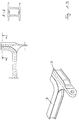
- FIG. 1.1 to 1.3 training according to the invention a cross strut 3, consisting of one seen in cross section Double T-shaped extruded profile shown.
- FIG. 1.1 and 1.2 are two different connection options sketched to a U-shaped side member 2 seen in cross section, with a weld pool support 10 in the connection zone is trained. The runs in this weld pool support Weld 11, wherein in Figure 1.1 a supplement 12 for Alignment with the bottom of the cross strut 3 is required.
- Figure 1.2 can be dispensed with because the arch shape the leg of the U-profile 2 is cut.
- the side member 2 has the cross section of a double-T profile, so that here similar to Figure 1.2 the adaptation to the curved Cross members in the transition zone from the roof area of the double-T profile can be cut out. From the illustrations shown is the construction according to Figure 1.3 in terms of Stiffness and the connection to the trailing arm at the cheapest educated.
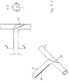
- Figure 2 shows a variant of the cross strut 3 according to the invention Connection to a side member 2 designed as a round tube.
- the roof of the double-T profile is ribbed here, with the ribs 3.1 and 3.2 flattened in the transition zone to the side member 2 are, so that a widening 13 arises, which is a cheaper Connection to the trailing arm enables.
- To record the flattening 13 are an upper and a on the trailing arm 2 lower weld pool support 14.1, 14.2 in the longitudinal direction of the trailing arm 2 arranged. This allows the power flow to be trouble-free be transferred from the cross strut 3 into the trailing arm 2.
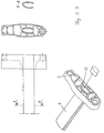
- Cross strut 3 shows Figure 3.
- Figure 3 is namely the central web of the notched double T-profile according to the invention, so that after Bending the ends 3.1, 3.2 a trailing arm 2 with a U-profile cross section arises.
- the Trailing link 2 with triangular insert plates 15.1, 15.2 welded.
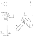
- the extruded profile of the cross strut 3 consists a V-shaped base profile that at the tapered ends Has thickenings to shift the center of the thrust.
- the thickenings 16.1, 16.2 are positioned in such a way that that for the respective construction of the twist beam axle cheapest thrust center is reached.
- a casting connection with triangular Cross section 17 provided that the power flow in one ribbed trailing arm 2 transferred.
- the trailing arm can be used as a casting 2 also be open-ended, what advantages offers storage and connection to the body frame.
- transverse strut 3 and trailing arms 2 from one piece.
- the cross strut 3 has a smooth transition at the Bend towards the trailing arm 2 has.
- To the cross strut 3 To make it torsionally soft, it became a bend on the inside provided with a slot 18 by machining molded into the tubular profile designed as an extruded tube is.
- the longitudinal strut is bent by welding the Cross strut 3 with a tubular extrusion 2 same Diameter produced, with a weld 19 the beveled End of the extrusion tube 2 and the correspondingly trimmed Pipe bend of the cross strut 3 connects.
- Figure 5.2 is analogous to 5.1, the longitudinal strut 2 from a pipe bend molded with a further extrusion 20 over a weld seam 21 is connected.
- the cross strut 3 can be Extruded pipe-shaped part via a further weld seam 22 be connected, whereby to adjust the torsional rigidity one wall side is provided with a slot 18.
- the cross strut 3 is also a slotted Pipe, in this case designed as an oval pipe.
- the connection to the longitudinal strut 2 is formed positively, since the Longitudinal strut 2 as a ribbed extruded profile or casting one, adapted to the outer shape of the cross strut 3 Receiving part 22 is provided.
- the actual connection can by gluing, welding or shrinking.
- Figure 5.4 are the profile cross sections of cross strut 3 and Trailing arm 2 as extruded profile cross sections with essentially round output cross-section.
- the peculiarity lies here in the shape of the trailing arm 2, which by hydroforming from an originally round pipe cross section to one spatially curved axis part with several axis extensions 23, 24, 25 was reshaped.
- Bearing bushes 26, 27, 28 drawn in and fixed by hydroforming.
- a weld pool support 29 trained, which extends into the interior of the cross strut.
- the the following figures are also intended to show other connection methods, around a torsion and bending resistant transition zone between the cross strut 3 and the trailing arm 2 to accomplish.
- the cross strut 3 with the trailing arm 2 connected by hydroforming.
- the recess can be made to fit precisely by milling or punching be carried out so that the trailing arm 2 is positively inserted can be (variant I).
- the positive connection between the cross strut 3 and the Trailing arm 2 can be crimped 7 in the head part 29 can still be improved.
- adhesives so that a material bond is achieved can be.
- mechanical joining processes such as Clinching or clinching or thermal processes such as e.g. Welding can be used.
- the slot level is indicated at 37.
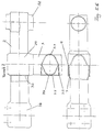
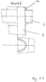
- cross strut 3 a reverse type of attachment is also possible possible between cross strut 3 and trailing arm 2 (see Fig. 5.7).
- the cross strut would not be deformed at the end, but the trailing arm 2 with the cutouts or widenings 41 provided, into which the cross strut 3 is inserted and through Hydroforming is connected.
- a mechanical connection can also be achieved by that the cross strut in the inserted state by hydroforming is expanded in the connecting zone (variant II).
- the ends 42.1, 42.2 of the profile 42 can be removed after removal a connecting piece 45 that between the weld pool supports 44.1, 44.2 is arranged, slightly bend outwards (see Fig.6.1). Those remaining at the bent ends 42.1, 42.2 Weld pool supports 44.1, 44.2 are in the U-shaped Trailing arm profile 2 inserted and welded there.
- the between the ends 42.1 and 42.2 or the outer edge of the U-shaped Trailing arm profile 2a opening is created by a gusset profile 46 or preferably by a suitably shaped sheet sealed by thermal joining.
- a corresponding butt weld can also be used as trailing arm 2 Connection of the profile 42 connected to the cross strut 3 using weld pool supports 44.1, 44.2.
- FIG. 6.1 is a wheel carrier plate 47 at one end of the Trailing arm 2 shown.
- the wheel carrier plate 47 consists of an extruded profile pressed in the direction of the arrow, whereby in mounting channels 48.1 - 48.4 for prepared to screw the axle support plate (not shown) can be.
- the trailing arm 2 is in a recess 49 of the extruded profile used and there firmly welded.
- a pipe connection 50 for arranged the inclusion of a rubber joint.
- the pipe connector is also with the trailing arm 2 via a weld connected, preferably a semicircular recess 51 for the secure fixation is prepared.
Landscapes
- Engineering & Computer Science (AREA)
- Mechanical Engineering (AREA)
- Vehicle Body Suspensions (AREA)
- Extrusion Of Metal (AREA)
Description
- Magnesium
- 0,4 - 1,4 %
- Silizium
- 0,4 - 1,5 %
- Kupfer
- 0,01 - 1,0 %
- Eisen
- 0,1 - 0,8 %
- Mangan
- 0,01 - 1,0 %
- Chrom max.
- 0,3 %
- Zircon max.
- 0,3 %
- Figur 1
- Erfindungsgemäße Querstrebe mit Doppel-T-Profilquerschnitt;
- Figur 2
- Querstrebe aus Doppel-T-Profil mit gerippter Dachfläche;
- Figur 3
- Querstrebe aus Doppel-T-Profil mit geschlitzter Dachfläche;
- Figur 4
- Querstrebe im V-Profil mit verstärkten Kanten;
- Figur 5
- Querstreben aus geschlitzten Rohren mit verschiedenen Anschlüssen für die Längsstrebe;
- Figur 6
- Querstrebe mit U-Profil-Querschnitt.
Claims (22)
- Kraftfahrzeug-Hinterachse des Verbundlenkerachs-Typs mit jeweils an ihrem hinteren Ende einen Radträger aufweisende Längslenker (2) hoher Biege- und Torsionssteifigkeit, sowie einer biegesteifen, für Torsionsbeanspruchungen jedoch nachgiebigen Querstrebe (3) aus einem, die Lage des Schubmittelpunktes verändernden Profilquerschnitt,
dadurch gekennzeichnet,daß die Querstrebe (3) aus einem Aluminiumstrangpreßprofil mit einem in Querstrebenlängsrichtung verlaufenden Strangpreßgefüge besteht unddaß zur Gestaltung des Eigenlenkverhaltens und Erhöhung der zulässigen Beanspruchungskraft die Querstrebe entweder als Doppel-T-Profil, als Hohlprofil oder als U- bzw. V-Profil ausgebildet ist, an dessen Enden Hohlkammern oder Verdickungen angeformt sind. - Kraftfahrzeug-Hinterachse nach Anspruch 1,
dadurch gekennzeichnet,daß das Strangpreßgefüge eine zeilige Anordnung von Primärausscheidungen des Typs AlMn, AlMnFe und AlFe aufweist. - Kraftfahrzeug-Hinterachse nach einem der vorhergehenden Ansprüche,
dadurch gekennzeichnet,daß das Aluminiumstrangpreßprofil aus einer Aluminiumlegierung mit folgender Zusammensetzung besteht:- Magnesium
- 0,4 - 1,4 %
- Silizium
- 0,4 - 1,5 %
- Kupfer
- 0,01 - 1,0 %
- Eisen
- 0,1 - 0,8 %
- Mangan
- 0,01 - 1,0 %
- Chrom max.
- 0,3 %
- Zircon max.
- 0,3 %
- Kraftfahrzeug-Hinterachse nach einem der vorhergehenden Ansprüche,
dadurch gekennzeichnet,daß der Profilquerschnitt der Querstrebe (3) in dem zum Längslenker (2) hin sich erstreckenden Übergangsbereich als geschlossenes Hohlprofil ausgebildet ist, während es in den übrigen Bereichen aus einem offenen Profilquerschnitt besteht, das im Strangpreßverfahren hergestellt wird. - Kraftfahrzeug-Hinterachse nach einem der vorhergehenden Ansprüche,
dadurch gekennzeichnet,daß das geschlossene Hohlprofil der Querstrebe (3) in Längsrichtung geschlitzt ist, wobei die Schlitzbreite zwischen 0,1 - 1 mm liegt. - Kraftfahrzeug-Hinterachse nach einem der vorhergehenden Ansprüche,
dadurch gekennzeichnet,daß die Dachflächen des die Querstrebe (3) bildenden Doppel-T-Profils gerippt oder gewellt sind, wobei in der Fügezone zum Längslenker hin eine Verbreiterung durch Plattdrücken der Wellen oder Rippen vorgesehen ist, die mit parallel hierzu verlaufenden Längsrippen eines als Rohrprofil ausgebildeten Längslenker verschweißt ist. - Kraftfahrzeug-Hinterachse nach einem der vorhergehenden Ansprüche,
dadurch gekennzeichnet,daß der Längslenker als Gußteil ausgebildet ist mit einer zur Querstrebe hin offenen Profilstruktur, in die die Querstrebe eingesteckt und verschweißt wird. - Kraftfahrzeug-Hinterachse nach einem der vorhergehenden Ansprüche,
dadurch gekennzeichnet,daß der Längslenker aus einem um 90 ° gebogenen Rohrprofil besteht, an dessen einem Ende die Querstrebe überlappend verschweißt ist und an dessen äußerem Bogen in Verlängerung des freien Bogenrohrprofils ein einseitig offenes Strangpreßprofil angeschweißt ist. - Kraftfahrzeug-Hinterachse nach einem der vorhergehenden Ansprüche,
dadurch gekennzeichnet,daß Querstrebe und Längslenker aus ineinandergesteckten Rohren bestehen, wobei die Querstrebe zumindest abschnittsweise geschlitzt ist und in Verlängerung des freien Bogenendes die Längslenker durch ein angeschweißtes Rohr mit schräg zur Rohrachse geführter Fügezone gebildet werden. - Verfahren zur Herstellung einer Kraftfahrzeug-Hinterachse des Verbundlenkerachs-Typs unter Verwendung von Quer- und Längslenkern gemäß einem der vorhergehenden Ansprüche,
dadurch gekennzeichnet,daß der Längslenker (2) durch einen quer zur Längsachse an seinem Ende durchbohrten Querträger durchgesteckt und durch Hydroformen form- und kraftschlüssig verbunden wird. - Verfahren nach dem vorhergehenden Anspruch,
dadurch gekennzeichnet,daß der Querlenker an seinen Enden zunächst durch Hydroforming aufgeweitet und in dem aufgeweiteten Abschnitt mit einer rechteckigen Aussparung versehen wird,daß in die rechteckige Aussparung der Längslenker (2) eingesteckt und durch Quetschverbindungen mit dem Querträger verbunden wird. - Verfahren nach einem der vorhergehenden Ansprüche,
dadurch gekennzeichnet,daß an den beiden Endpunkten jedes Längslenkers Querschnittsausprägungen durch Hydroforming zur Ausbildung einer Radträgerplatte und zur Aufnahme eines Gummigelenkes ausgeformt werden. - Verfahren nach einem der vorhergehenden Ansprüche,
dadurch gekennzeichnet,daß die Verbindungszonen durch Klebstoffe und/oder Clinchpunkte erzeugt werden. - Verfahren nach einem der vorhergehenden Ansprüche,
dadurch gekennzeichnet,daß der Querträger zur Verlagerung des Schubmittelpunktes und zur Einstellung der Torsionssteifigkeit mit einem Fräswerkzeug geschlitzt wird. - Verfahren nach einem der vorhergehenden Ansprüche,
dadurch gekennzeichnet,daß für die Befestigung von Lager oder Drehpunkten in die Wandungen des Trägers gestülpte Buchsen eingeformt werden. - Verfahren nach einem der vorhergehenden Ansprüche,
dadurch gekennzeichnet,daß in die gestülpten Buchsen Hohlwellen eingezogen und durch Hydroformen fixiert werden. - Verfahren nach einem der vorhergehenden Ansprüche,
dadurch gekennzeichnet,daß an den geschlitzten Enden des Querträgers geschlossene Hohlprofile angeordnet sind zur Verlagerung des Schubmittelpunktes und Beeinflussung der Torsionssteifigkeit. - Verfahren nach einem der vorhergehenden Ansprüche,
dadurch gekennzeichnet,daß die Schweißnähte als Stumpfnähte ausgebildet sind mit einer Badsicherung, wobei die Schweißbadstützen in der Hauptbeanspruchungsrichtung verlaufen und durch Strangpressen an eines der beiden Profile angeformt sind. - Verfahren nach einem der vorhergehenden Ansprüche,
dadurch gekennzeichnet,daß das geschlossene Hohlprofil der Querstrebe (3) durch mechanische Bearbeitung geschlitzt und gleichzeitig an den Kanten verdichtet wird. - Verfahren nach einem der vorhergehenden Ansprüche,
dadurch gekennzeichnet,daß die Enden (42.1, 42.2) eines in die Querstrebe (3) übergehenden U-Profils (42) nach dem Entfernen eines Verbindungsstückes (45) nach außen aufgebogen und mit den integrierten Schweißbadstützen (44.1, 44.2) in ein U-förmiges Längslenkerprofil (2) eingeschoben und verschweißt werden. - Verfahren nach einem der vorhergehenden Ansprüche,
dadurch gekennzeichnet,daß in die zwischen den aufgebogenen Enden (42.1, 42.2) entstehende Lücke ein Zwickelprofil (46) oder ein entsprechend geformtes Blech eingesetzt und mit den Nachbarprofilen thermisch verbunden wird. - Verfahren nach einem der vorhergehenden Ansprüche,
dadurch gekennzeichnet,daß an den offenen Enden der Querstrebe (3) Hohlkammern (43.1 und 43.2) ausgebildet sind, wobei durch Verschiebung oder Querschnittsänderung der Hohlkammern eine Verlagerung des Schubmittelpunktes erfolgt.
Applications Claiming Priority (2)
| Application Number | Priority Date | Filing Date | Title |
|---|---|---|---|
| DE4441971A DE4441971A1 (de) | 1994-11-25 | 1994-11-25 | Kraftfahrzeug-Hinterachse und Verfahren zu ihrer Herstellung |
| DE4441971 | 1994-11-25 |
Publications (2)
| Publication Number | Publication Date |
|---|---|
| EP0713791A1 EP0713791A1 (de) | 1996-05-29 |
| EP0713791B1 true EP0713791B1 (de) | 1999-01-27 |
Family
ID=6534122
Family Applications (1)
| Application Number | Title | Priority Date | Filing Date |
|---|---|---|---|
| EP95118110A Expired - Lifetime EP0713791B1 (de) | 1994-11-25 | 1995-11-17 | Kraftfahrzeug-Hinterachse und Verfahren zu ihrer Herstellung |
Country Status (4)
| Country | Link |
|---|---|
| US (1) | US5800024A (de) |
| EP (1) | EP0713791B1 (de) |
| DE (2) | DE4441971A1 (de) |
| ES (1) | ES2133647T3 (de) |
Cited By (3)
| Publication number | Priority date | Publication date | Assignee | Title |
|---|---|---|---|---|
| CN101878125B (zh) * | 2007-10-27 | 2013-05-29 | 施米茨货车股份有限公司 | 用于商用车辆的轴联动装置以及用于制造该轴联动装置的方法 |
| CN103282221A (zh) * | 2010-11-05 | 2013-09-04 | 雷诺股份公司 | 用于机动车辆的部分粘附的挠性车桥 |
| DE102020108494A1 (de) | 2020-03-27 | 2021-09-30 | Man Truck & Bus Se | Trägerkonstruktion für ein Kraftfahrzeug, insbesondere zum Tragen von Feder- und/oder Dämpfungselementen |
Families Citing this family (50)
| Publication number | Priority date | Publication date | Assignee | Title |
|---|---|---|---|---|
| FR2737177B1 (fr) * | 1995-07-28 | 1997-09-05 | Vallourec Vitry | Berceau tubulaire pour vehicule automobile |
| DE19604286C1 (de) * | 1996-02-07 | 1997-07-24 | Benteler Werke Ag | Verbundlenkerachse für Kraftfahrzeuge |
| DE19735914B4 (de) * | 1996-08-31 | 2008-04-17 | Volkswagen Ag | Radführungslenker und Verfahren zu seiner Herstellung |
| FR2753931B1 (fr) * | 1996-09-30 | 2002-02-15 | Peugeot | Suspension de roue de vehicule automobile |
| DE19643001A1 (de) * | 1996-10-18 | 1998-04-23 | Audi Ag | Radaufhängung für Kraftfahrzeuge |
| DE59609341D1 (de) * | 1996-11-05 | 2002-07-18 | Alcan Tech & Man Ag | Radaufhängung |
| DE19649076B4 (de) * | 1996-11-27 | 2006-10-05 | Benteler Ag | Verfahren zur Herstellung einer Verbundlenkerachse für Kraftfahrzeuge und Verbundlenkerachse |
| DE19752347B4 (de) * | 1996-12-07 | 2006-06-01 | Volkswagen Ag | Verbundlenker-Hinterachse und Verfahren zu ihrer Herstellung |
| DE19707643C1 (de) | 1997-02-26 | 1998-12-24 | Ford Global Tech Inc | Verbundlenker-Hinterachse für Kraftfahrzeuge |
| DE29718751U1 (de) * | 1997-10-04 | 1998-02-12 | Otto Sauer Achsenfabrik Keilberg, 63856 Bessenbach | Achsaufhängung für Fahrzeuge |
| DE19750067B4 (de) * | 1997-11-12 | 2006-04-27 | Behr Gmbh & Co. Kg | Verfahren zum Fügen eines Bauteils an einen Hohlkörper und dadurch herstellbarer Halter-Rohrelement-Komplex |
| DE19751459B4 (de) * | 1997-11-20 | 2007-10-25 | Volkswagen Ag | Verbundlenker-Hinterachse |
| DE19846399A1 (de) * | 1998-10-08 | 2000-04-13 | Volkswagen Ag | Verbundlenker-Hinterachse |
| DE19939485A1 (de) | 1999-08-20 | 2001-02-22 | Opel Adam Ag | Verbundlenkerhinterachse |
| NO314928B1 (no) | 1999-11-03 | 2003-06-16 | Raufoss Tech As | B¶rearm |
| DE19961425B4 (de) * | 1999-12-17 | 2005-10-20 | Zf Lemfoerder Metallwaren Ag | Kraftfahrzeugbauteil |
| US6523841B2 (en) * | 2000-05-31 | 2003-02-25 | Benteler Ag | Twist-beam axle for motor vehicles |
| US6533300B1 (en) | 2000-06-02 | 2003-03-18 | Oxford Suspension, Inc. | Trailing twist axle and method of manufacture |
| DE10027729A1 (de) * | 2000-06-03 | 2001-12-06 | Volkswagen Ag | Fahrzeugstarrachse |
| DE10060312C5 (de) * | 2000-07-06 | 2010-07-22 | Saf-Holland Gmbh | Fahrzeugachse |
| FR2822104B1 (fr) * | 2001-03-15 | 2003-06-13 | Vallourec Vitry | Fixation perfectionnee d'une traverse et de bras, notamment dabs un essieu semi-rigide |
| DE10116748B4 (de) * | 2001-04-04 | 2006-10-05 | Benteler Automobiltechnik Gmbh | Querstrebe für eine Verbundlenkerachse |
| US6609764B2 (en) * | 2001-04-27 | 2003-08-26 | The Boler Company | Fabricated vehicle axle |
| ITTO20010926A1 (it) * | 2001-09-28 | 2003-03-28 | Fiat Auto Spa | Sospensione posteriore a ruote interconnesse per un autoveicolo, e metodo per realizzare tale sospensione posteriore. |
| ITTO20020959A1 (it) * | 2002-11-07 | 2004-05-08 | Sistemi Sospensioni Spa | Ponte torcente per la sospensione posteriore di un |
| GB2396140C (en) * | 2002-12-13 | 2011-06-23 | Meritor Heavy Vehicle Sys Ltd | A suspension trailing arm and method of making a suspension trailing arm |
| US6817511B2 (en) * | 2002-12-16 | 2004-11-16 | Dana Corporation | Method for joining axle components |
| US6860013B1 (en) | 2002-12-16 | 2005-03-01 | Dana Corporation | Method for joining suspension components |
| US6813818B2 (en) | 2002-12-24 | 2004-11-09 | Dana Corporation | Method for joining vehicle frame components |
| DE102004009723A1 (de) * | 2004-02-25 | 2005-10-06 | Zf Friedrichshafen Ag | Gebauter Radführungslenker |
| FR2876629B1 (fr) * | 2004-10-18 | 2007-02-02 | Renault Sas | Train de vehicule automobile assemble par collage structural |
| DE102004055100B4 (de) * | 2004-11-15 | 2011-07-14 | Benteler Automobiltechnik GmbH, 33102 | Achskonstruktion für ein Kraftfahrzeug |
| DE102005038274C5 (de) * | 2005-08-12 | 2018-01-11 | Saf-Holland Gmbh | Radaufhängungslenker |
| US20070047082A1 (en) * | 2005-08-23 | 2007-03-01 | Seaver Sean P | Welded, multiple piece cast control arm |
| US20070069496A1 (en) * | 2005-09-27 | 2007-03-29 | Rinehart Ronald A | Torsion beam suspension member |
| JP4344352B2 (ja) * | 2005-12-05 | 2009-10-14 | 本田技研工業株式会社 | トーションビーム式サスペンション |
| WO2008122107A1 (en) * | 2007-04-06 | 2008-10-16 | Magna International Inc. | Stress reducing inner sleeve for twist beam and associated method |
| JP4692578B2 (ja) * | 2008-05-30 | 2011-06-01 | トヨタ自動車株式会社 | 車両のサスペンションアーム |
| CA2644464C (en) | 2008-10-17 | 2010-04-20 | Arcelormittal Tubular Products Canada Inc. | Twist-axle of variable wall thickness |
| DE102010013518A1 (de) | 2010-03-31 | 2011-10-06 | Trw Automotive Gmbh | Verbindungsstrebe |
| DE102010030644B4 (de) | 2010-06-29 | 2022-03-03 | Ford Global Technologies, Llc | Verbundlenkerachse für Kraftfahrzeuge |
| DE102011086481B4 (de) * | 2011-11-16 | 2020-06-10 | Saf-Holland Gmbh | Fahrwerksystem für Nutzfahrzeuge |
| DE102011055993B3 (de) | 2011-12-02 | 2013-03-21 | Benteler Automobiltechnik Gmbh | Kraftfahrzeug-Fahrwerkskomponente |
| DE102012216246A1 (de) | 2012-09-13 | 2014-03-13 | Saf-Holland Gmbh | Achslenker-Knoteneinheit |
| US20140232177A1 (en) * | 2013-02-15 | 2014-08-21 | Arvinmeritor Technology, Llc | Axle assembly and a method of manufacture |
| DE102014105904A1 (de) | 2014-04-28 | 2015-10-29 | Benteler Automobiltechnik Gmbh | Verbundlenkerachse und Verfahren zur Herstellung eines Torsionsprofils |
| DE102014221472A1 (de) * | 2014-10-22 | 2016-04-28 | Volkswagen Aktiengesellschaft | Querträger für eine Verbundlenkerachse |
| US10202013B2 (en) * | 2016-03-01 | 2019-02-12 | Dura Operating, Llc | Extruded suspension linkage |
| DE102017218422A1 (de) | 2017-10-16 | 2019-04-18 | Bayerische Motoren Werke Aktiengesellschaft | Versteifungsbauteil, Kraftfahrzeug und Verfahren zum Herstellen eines Versteifungsbauteils |
| DE102019209784A1 (de) * | 2019-07-03 | 2021-01-07 | Ford Global Technologies, Llc | Verbundlenkerachse mit mehrteiligem Längslenker |
Family Cites Families (13)
| Publication number | Priority date | Publication date | Assignee | Title |
|---|---|---|---|---|
| DE2459519B1 (de) * | 1974-12-17 | 1976-04-22 | Daimler Benz Ag | Fahrzeugrahmen |
| US4082578A (en) * | 1976-08-05 | 1978-04-04 | Aluminum Company Of America | Aluminum structural members for vehicles |
| JPS57154574U (de) * | 1981-03-26 | 1982-09-28 | ||
| US4593949A (en) * | 1983-09-28 | 1986-06-10 | Mazda Motor Corporation | Lower body construction for motor vehicle |
| US4842298A (en) * | 1988-02-29 | 1989-06-27 | Patrick Jarvis | Sway bar for all terrain vehicle |
| DE3918283C1 (de) * | 1989-06-05 | 1990-05-31 | Audi Ag, 8070 Ingolstadt, De | |
| JP2532325Y2 (ja) * | 1990-03-30 | 1997-04-16 | マツダ株式会社 | 車両の下部車体構造 |
| JPH058757A (ja) * | 1991-06-29 | 1993-01-19 | Mazda Motor Corp | 自動車の後部構造 |
| DE4142325C2 (de) * | 1991-12-20 | 1996-06-13 | Bayerische Motoren Werke Ag | Verfahren zum Herstellen von Fahrwerksträgern |
| US5271687A (en) * | 1992-04-03 | 1993-12-21 | Ford Motor Company | Space frame joint construction |
| US5332281A (en) * | 1992-04-30 | 1994-07-26 | Ford Motor Company | Space frame construction |
| DE4330192B4 (de) * | 1992-09-16 | 2005-07-07 | Volkswagen Ag | Kraftfahrzeug-Hinterachse des Verbundlenkerachs-Typs |
| JPH07257425A (ja) * | 1994-03-18 | 1995-10-09 | Honda Motor Co Ltd | 自動車用車体のサブフレーム取付け構造 |
-
1994
- 1994-11-25 DE DE4441971A patent/DE4441971A1/de not_active Withdrawn
-
1995
- 1995-11-17 DE DE59504971T patent/DE59504971D1/de not_active Expired - Fee Related
- 1995-11-17 EP EP95118110A patent/EP0713791B1/de not_active Expired - Lifetime
- 1995-11-17 ES ES95118110T patent/ES2133647T3/es not_active Expired - Lifetime
- 1995-11-21 US US08/561,101 patent/US5800024A/en not_active Expired - Lifetime
Cited By (4)
| Publication number | Priority date | Publication date | Assignee | Title |
|---|---|---|---|---|
| CN101878125B (zh) * | 2007-10-27 | 2013-05-29 | 施米茨货车股份有限公司 | 用于商用车辆的轴联动装置以及用于制造该轴联动装置的方法 |
| CN103282221A (zh) * | 2010-11-05 | 2013-09-04 | 雷诺股份公司 | 用于机动车辆的部分粘附的挠性车桥 |
| CN103282221B (zh) * | 2010-11-05 | 2016-01-20 | 雷诺股份公司 | 用于机动车辆的部分粘附的挠性车桥 |
| DE102020108494A1 (de) | 2020-03-27 | 2021-09-30 | Man Truck & Bus Se | Trägerkonstruktion für ein Kraftfahrzeug, insbesondere zum Tragen von Feder- und/oder Dämpfungselementen |
Also Published As
| Publication number | Publication date |
|---|---|
| ES2133647T3 (es) | 1999-09-16 |
| EP0713791A1 (de) | 1996-05-29 |
| DE59504971D1 (de) | 1999-03-11 |
| DE4441971A1 (de) | 1996-05-30 |
| US5800024A (en) | 1998-09-01 |
Similar Documents
| Publication | Publication Date | Title |
|---|---|---|
| EP0713791A1 (de) | Kraftfahrzeug-Hinterachse und Verfahren zu ihrer Herstellung | |
| EP0916530B1 (de) | Verbundlenkerachse für Kraftfahrzeuge | |
| DE102008020694B4 (de) | Kraftfahrzeugrahmen | |
| EP1036679B1 (de) | Verbundlenkerhinterachse | |
| DE102006062889B4 (de) | Hilfsrahmen, insbesondere für Kraftfahrzeuge | |
| DE102007030929B4 (de) | Achsträger für Kraftfahrzeuge | |
| DE19605283B4 (de) | Längslenkeraufhängung für Fahrzeuge | |
| DE4003922C2 (de) | ||
| EP2674309B1 (de) | Verbundlenkerachse mit Verstärkungsblech | |
| DE10110492A1 (de) | Lenker für eine Radaufhängung | |
| DE102008036340A1 (de) | Kraftfahrzeug mit einer Verbundlenkerachse | |
| DE112006000143B4 (de) | Instrumentenbrettquerträger | |
| DE10054692B4 (de) | Verbundlenkerachse | |
| DE10107960A1 (de) | Hilfsrahmen für ein Kraftfahrzeug | |
| DE102004009722A1 (de) | Radführungslenker | |
| DE10011845B4 (de) | Lenker in Schalenbauweise | |
| DE19519303B4 (de) | Dreiecklenker für eine Kraftfahrzeug-Einzelradaufhängung | |
| DE19846400B4 (de) | Verbundlenker-Hinterachse | |
| DE10024225A1 (de) | Einschaliger Lenker für eine Fahrzeugradaufhängung und Verfahren zur Herstellung eines solchen Lenkers | |
| DE10351954A1 (de) | Verbundlenkerachse und Verfahren zur Herstellung eines Querträgers | |
| DE69600251T2 (de) | Halbsteife Achse für ein Fahrzeug | |
| DE10122998A1 (de) | Verbundlenkerachse und Verfahren zur Herstellung eines Querträgers | |
| EP1749678B1 (de) | Achskörper für Nutzfahrzeugachsen | |
| DE102008049784B4 (de) | Verstärkungsanordnung für eine Türsäule eines Personenkraftwagens | |
| EP3450041B1 (de) | Verfahren zur herstellung eines rohrförmigen hohlkörpers aus einer zugeschnittenen metallischen platine und fahrwerks- oder karosseriebauteil mit einem nach dem verfahren hergestellten hohlkörper |
Legal Events
| Date | Code | Title | Description |
|---|---|---|---|
| PUAI | Public reference made under article 153(3) epc to a published international application that has entered the european phase |
Free format text: ORIGINAL CODE: 0009012 |
|
| 17P | Request for examination filed |
Effective date: 19960316 |
|
| AK | Designated contracting states |
Kind code of ref document: A1 Designated state(s): DE ES FR GB IT PT SE |
|
| 17Q | First examination report despatched |
Effective date: 19961108 |
|
| GRAG | Despatch of communication of intention to grant |
Free format text: ORIGINAL CODE: EPIDOS AGRA |
|
| GRAG | Despatch of communication of intention to grant |
Free format text: ORIGINAL CODE: EPIDOS AGRA |
|
| GRAH | Despatch of communication of intention to grant a patent |
Free format text: ORIGINAL CODE: EPIDOS IGRA |
|
| GRAH | Despatch of communication of intention to grant a patent |
Free format text: ORIGINAL CODE: EPIDOS IGRA |
|
| GRAA | (expected) grant |
Free format text: ORIGINAL CODE: 0009210 |
|
| AK | Designated contracting states |
Kind code of ref document: B1 Designated state(s): DE ES FR GB IT PT SE |
|
| REF | Corresponds to: |
Ref document number: 59504971 Country of ref document: DE Date of ref document: 19990311 |
|
| ITF | It: translation for a ep patent filed | ||
| GBT | Gb: translation of ep patent filed (gb section 77(6)(a)/1977) |
Effective date: 19990406 |
|
| ET | Fr: translation filed | ||
| REG | Reference to a national code |
Ref country code: ES Ref legal event code: FG2A Ref document number: 2133647 Country of ref document: ES Kind code of ref document: T3 |
|
| PLBE | No opposition filed within time limit |
Free format text: ORIGINAL CODE: 0009261 |
|
| STAA | Information on the status of an ep patent application or granted ep patent |
Free format text: STATUS: NO OPPOSITION FILED WITHIN TIME LIMIT |
|
| 26N | No opposition filed | ||
| REG | Reference to a national code |
Ref country code: GB Ref legal event code: IF02 |
|
| PGFP | Annual fee paid to national office [announced via postgrant information from national office to epo] |
Ref country code: PT Payment date: 20031008 Year of fee payment: 9 |
|
| PGFP | Annual fee paid to national office [announced via postgrant information from national office to epo] |
Ref country code: ES Payment date: 20031127 Year of fee payment: 9 |
|
| PGFP | Annual fee paid to national office [announced via postgrant information from national office to epo] |
Ref country code: SE Payment date: 20031201 Year of fee payment: 9 |
|
| PG25 | Lapsed in a contracting state [announced via postgrant information from national office to epo] |
Ref country code: SE Free format text: LAPSE BECAUSE OF NON-PAYMENT OF DUE FEES Effective date: 20041118 Ref country code: ES Free format text: LAPSE BECAUSE OF NON-PAYMENT OF DUE FEES Effective date: 20041118 |
|
| PGFP | Annual fee paid to national office [announced via postgrant information from national office to epo] |
Ref country code: GB Payment date: 20041119 Year of fee payment: 10 Ref country code: FR Payment date: 20041119 Year of fee payment: 10 |
|
| PGFP | Annual fee paid to national office [announced via postgrant information from national office to epo] |
Ref country code: DE Payment date: 20050111 Year of fee payment: 10 |
|
| PG25 | Lapsed in a contracting state [announced via postgrant information from national office to epo] |
Ref country code: PT Free format text: LAPSE BECAUSE OF NON-PAYMENT OF DUE FEES Effective date: 20050517 |
|
| EUG | Se: european patent has lapsed | ||
| REG | Reference to a national code |
Ref country code: PT Ref legal event code: MM4A Effective date: 20050517 |
|
| PG25 | Lapsed in a contracting state [announced via postgrant information from national office to epo] |
Ref country code: IT Free format text: LAPSE BECAUSE OF NON-PAYMENT OF DUE FEES;WARNING: LAPSES OF ITALIAN PATENTS WITH EFFECTIVE DATE BEFORE 2007 MAY HAVE OCCURRED AT ANY TIME BEFORE 2007. THE CORRECT EFFECTIVE DATE MAY BE DIFFERENT FROM THE ONE RECORDED. Effective date: 20051117 Ref country code: GB Free format text: LAPSE BECAUSE OF NON-PAYMENT OF DUE FEES Effective date: 20051117 |
|
| REG | Reference to a national code |
Ref country code: ES Ref legal event code: FD2A Effective date: 20041118 |
|
| PG25 | Lapsed in a contracting state [announced via postgrant information from national office to epo] |
Ref country code: DE Free format text: LAPSE BECAUSE OF NON-PAYMENT OF DUE FEES Effective date: 20060601 |
|
| GBPC | Gb: european patent ceased through non-payment of renewal fee |
Effective date: 20051117 |
|
| PG25 | Lapsed in a contracting state [announced via postgrant information from national office to epo] |
Ref country code: FR Free format text: LAPSE BECAUSE OF NON-PAYMENT OF DUE FEES Effective date: 20060731 |
|
| REG | Reference to a national code |
Ref country code: FR Ref legal event code: ST Effective date: 20060731 |