EP0713740B1 - Bohrwerkzeug - Google Patents
Bohrwerkzeug Download PDFInfo
- Publication number
- EP0713740B1 EP0713740B1 EP95810519A EP95810519A EP0713740B1 EP 0713740 B1 EP0713740 B1 EP 0713740B1 EP 95810519 A EP95810519 A EP 95810519A EP 95810519 A EP95810519 A EP 95810519A EP 0713740 B1 EP0713740 B1 EP 0713740B1
- Authority
- EP
- European Patent Office
- Prior art keywords
- groove
- drilling tool
- receiving groove
- insertion end
- parts
- Prior art date
- Legal status (The legal status is an assumption and is not a legal conclusion. Google has not performed a legal analysis and makes no representation as to the accuracy of the status listed.)
- Expired - Lifetime
Links
- 238000005553 drilling Methods 0.000 title claims description 27
- 230000037431 insertion Effects 0.000 claims description 26
- 238000003780 insertion Methods 0.000 claims description 26
- 239000004575 stone Substances 0.000 description 1
Images

Classifications
-
- B—PERFORMING OPERATIONS; TRANSPORTING
- B23—MACHINE TOOLS; METAL-WORKING NOT OTHERWISE PROVIDED FOR
- B23B—TURNING; BORING
- B23B51/00—Tools for drilling machines
- B23B51/04—Drills for trepanning
- B23B51/0473—Details about the connection between the driven shaft and the tubular cutting part; Arbors
-
- B—PERFORMING OPERATIONS; TRANSPORTING
- B28—WORKING CEMENT, CLAY, OR STONE
- B28D—WORKING STONE OR STONE-LIKE MATERIALS
- B28D1/00—Working stone or stone-like materials, e.g. brick, concrete or glass, not provided for elsewhere; Machines, devices, tools therefor
- B28D1/14—Working stone or stone-like materials, e.g. brick, concrete or glass, not provided for elsewhere; Machines, devices, tools therefor by boring or drilling
Definitions
- the invention relates to a drilling tool with a first forming an insertion end Part and a second part forming a carrier part occupied by drilling cutting edges, wherein There is a threaded connection between the two parts and on both parts with each other interacting stop surfaces are arranged.
- Drilling tools For making large holes in masonry, concrete or stone Drilling tools are used which have a carrier part which is connected to an annular End face is provided with cutting edges. When drilling the hole in question First an inner core remains, which is then used with a suitable tool is broken out.
- a drilling tool known from DE-GM 18 97 841 consists of an insertion end and a support part studded with drilling cutters, the Inserting end and the support part connected to each other via a threaded connection are.
- the carrier parts and the insertion ends have uniform connection points.
- the carrier parts and the insertion ends have uniform connection points.
- the threaded connection of the drilling tools is solvable, there is a possibility that a non-specialist can use the drilling tool can unscrew and another, for example, on the insertion end Carrier part screws. Is the combination of insertion end created by the non-specialist and carrier part not in the range of permissible combinations, this can for example, insufficient drilling progress or damage to the Guide the drilling tool or the drive unit.
- the invention has for its object a drilling tool with insertion end To create the support part, which is permitted by a specialist Combination cannot be separated again.
- the object is achieved in that on one of the two parts a groove and on the other part a receiving groove with an inserted, radially resilient Spring ring is arranged, the distance of the groove from the stop surface of the the part having the groove the distance of the receiving groove from the stop surface of the corresponds to the receiving groove part.
- the threaded connection both parts connected.
- the spring washer of one Grooved part radially expanded and at least partially penetrated by this. If the stop surface of the carrier part on the stop surface of the insertion end comes to the system, the widened spring ring jumps into the groove and thus puts it the part having the groove, on the part having the receiving groove axially fixed.
- the part having the groove preferably has an external thread, the length of which corresponds at most to the distance of the groove from the stop surface. This will damage it of the external thread on the part having the groove prevented if this at least partially penetrates the spring washer.
- the part having the groove expediently has between the external thread and the free end projecting into the part having the receiving groove Guide area with an outer diameter that is smaller than that Core diameter of the external thread.
- the smallest outside diameter of the guide area is smaller than the inner diameter of the relaxed Spring washer.
- the support part of which has a small diameter is advantageous the part of the carrier part which has the groove and the part which has the receiving groove Part formed from the insertion end.
- the support part of which has a large diameter is preferred the part having the groove from the insertion end and the receiving groove having part formed by the carrier part.
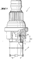
- the drilling tool shown in FIG. 1 is composed of an insertion end 1 and a carrier part 2 occupied with cutting edges 8 together. Both parts are about one Threaded connection connected to each other.
- the insertion end 1 has one, in one central opening arranged, circumferentially formed receiving groove 10, in which a radially resilient spring ring 7 is inserted. Between the receiving groove 10 and the stop surface 3, the insertion end 1 has an internal thread, which has an external thread 6 of the carrier part 2 cooperates.
- the external thread 6 extends from the stop surface 4 to a circumferential groove 9.
- the distance A the groove 9 from the stop surface 4 of the carrier part 2 corresponds to the distance B Receiving groove 10 from the stop surface 3 of the insertion end 7.
- the carrier part 2 has between the groove 9 and the free end 11 of the carrier part 2 a guide area 5, which has an outer diameter that is smaller than that Core diameter of the external thread 6.
- the guide area 5 tapers to free end 11 of the carrier part 2, the smallest outside diameter D being smaller than the inside diameter of the relaxed spring washer.
- the drilling tool shown in Fig. 2 consists of an insertion end 21 and a carrier part 22, which is equipped with cutting edges 28. Both parts are over a threaded connection connected to each other.
- the carrier part 22 has the one Drilling cutting 28 opposite area a central through hole, in which is arranged a circumferentially formed receiving groove 30.
- the receiving groove 30 serves to receive and guide a radially resilient spring ring 27.
- Between the receiving groove 30 and the stop surface 24 has the through hole of Carrier part 22 has an internal thread, which with an external thread 26 of the Inserting 21 interacts.
- the external thread 26 extends from the Stop surface 23 up to a circumferential groove 29 on the outside the insertion end 21 is arranged.
- the distance A of the groove 29 from the stop surface 23 of the insertion end 21 corresponds to the distance B of the receiving groove 30 from the Stop surface 24 of the carrier part 22.
- the insertion end has between the groove 29 and the free end 31 of the insertion end 21 21 a guide region 25 which has an outer diameter which is smaller than the core diameter of the external thread 26.
- the guide area 25 tapers to the free end 31 of the insertion end 21, the smallest outside diameter D is smaller than the inner diameter of the relaxed spring ring 27.
Landscapes
- Engineering & Computer Science (AREA)
- Mechanical Engineering (AREA)
- Mining & Mineral Resources (AREA)
- Drilling Tools (AREA)
- Processing Of Stones Or Stones Resemblance Materials (AREA)
- Auxiliary Devices For Machine Tools (AREA)
- Surgical Instruments (AREA)
- Cutting Tools, Boring Holders, And Turrets (AREA)
- Drilling And Boring (AREA)
- Earth Drilling (AREA)
- Holo Graphy (AREA)
Description
- Fig. 1
- ein erfindungsgemässes Bohrwerkzeug mit einem eine Nut aufweisenden Trägerteil und eine Aufnahmenut aufweisenden Einsteckende;
- Fig. 2
- ein weiteres Bohrwerkzeug mit einem eine Nut aufweisenden Einsteckende und einem Aufnahmenut aufweisenden Trägerteil.
Claims (6)
- Bohrwerkzeug mit einem, ein Einsteckende (1, 21) bildenden ersten Teil und einem, ein mit Bohrschneiden (8, 28) besetztes Trägerteil (2, 22) bildenden zweiten Teil, wobei zwischen den beiden Teilen eine Gewindeverbindung besteht und an beiden Teilen miteinander zusammenwirkende Anschlagflächen (3, 4, 23, 24) angeordnet sind, dadurch gekennzeichnet, dass an einem der beiden Teile eine Nut (9, 29) und am jeweils anderen Teil eine Aufnahmenut (10, 30) mit einliegendem, radial federbaren Federring (7, 27) angeordnet ist, wobei der Abstand (A) der Nut (9, 29) von der Anschlagfläche (4, 23) des die Nut (9, 29) aufweisenden Teiles dem Abstand (B) der Aufnahmenut (10, 30) von der Anschlagfläche (3, 24) des die Aufnahmenut (10, 30) aufweisenden Teiles entspricht.
- Bohrwerkzeug nach Anspruch 1, dadurch gekennzeichnet, dass der die Nut (9, 29) aufweisende Teil ein Aussengewinde (6, 26) trägt, dessen Länge höchstens dem Abstand (A) der Nut (9, 29) von der Anschlagfläche (4, 23) entspricht.
- Bohrwerkzeug nach Anspruch 2, dadurch gekennzeichnet, dass das die Nut (9, 29) aufweisende Teil zwischen dem Aussengewinde (6, 26) und dem in das die Aufnahmenut (10, 20) aufweisenden Teil ragenden freien Ende (11, 31) einen Führungsbereich (5, 25) mit einem Aussendurchmesser aufweist, der kleiner ist als der Kerndurchmesser des Aussengewindes (6, 26).
- Bohrwerkzeug nach Anspruch 3, dadurch gekennzeichnet, dass sich der Führungsbereich (5, 25) zum freien Ende (11, 31) hin verjüngt, wobei der kleinste Aussendurchmesser (D) des Führungsbereiches (5, 25) kleiner ist als der Innendurchmesser des entspannten Federringes (7, 27).
- Bohrwerkzeug nach einem der Ansprüche 1 bis 4, dadurch gekennzeichnet, dass das die Nut (9) aufweisende Teil vom Trägerteil (2) und das die Aufnahmenut (10) aufweisende Teil vom Einsteckende (1) gebildet ist.
- Bohrwerkzeug nach einem der Ansprüche 1 bis 4, dadurch gekennzeichnet, dass das die Nut (29) aufweisende Teil vom Einsteckende (21) und das die Aufnahmenut (30) aufweisende Teil vom Trägerteil (22) gebildet ist.
Applications Claiming Priority (2)
| Application Number | Priority Date | Filing Date | Title |
|---|---|---|---|
| DE4437952A DE4437952C2 (de) | 1994-10-24 | 1994-10-24 | Bohrwerkzeug |
| DE4437952 | 1994-10-24 |
Publications (2)
| Publication Number | Publication Date |
|---|---|
| EP0713740A1 EP0713740A1 (de) | 1996-05-29 |
| EP0713740B1 true EP0713740B1 (de) | 1998-03-18 |
Family
ID=6531554
Family Applications (1)
| Application Number | Title | Priority Date | Filing Date |
|---|---|---|---|
| EP95810519A Expired - Lifetime EP0713740B1 (de) | 1994-10-24 | 1995-08-17 | Bohrwerkzeug |
Country Status (14)
| Country | Link |
|---|---|
| US (1) | US5655613A (de) |
| EP (1) | EP0713740B1 (de) |
| JP (1) | JPH08206907A (de) |
| KR (1) | KR100351538B1 (de) |
| CN (1) | CN1057719C (de) |
| AT (1) | ATE164103T1 (de) |
| AU (1) | AU695474B2 (de) |
| CA (1) | CA2161034C (de) |
| DE (2) | DE4437952C2 (de) |
| ES (1) | ES2113719T3 (de) |
| MX (1) | MX9504445A (de) |
| NO (1) | NO306288B1 (de) |
| PL (1) | PL178380B1 (de) |
| TW (1) | TW324044B (de) |
Families Citing this family (7)
| Publication number | Priority date | Publication date | Assignee | Title |
|---|---|---|---|---|
| AT5068U1 (de) * | 2001-03-07 | 2002-03-25 | Schraml Glastechnik Gmbh | Vorrichtung an diamant-hohlbohrern |
| US6739411B2 (en) * | 2002-06-27 | 2004-05-25 | Good Earth Tools, Inc. | Hollow auger head assembly |
| DE10256043A1 (de) * | 2002-11-30 | 2004-06-09 | Hilti Ag | Werkzeugaufnahme für Kernbohrkronen |
| DE10256050A1 (de) * | 2002-11-30 | 2004-06-09 | Hilti Ag | Werkzeugaufnahme für Kernbohrkronen |
| DE102011089546A1 (de) * | 2011-12-22 | 2013-06-27 | Hilti Aktiengesellschaft | Bohrkrone mit einem austauschbaren Bohrkronenabschnitt |
| EP2886230A1 (de) * | 2013-12-20 | 2015-06-24 | HILTI Aktiengesellschaft | Bohrkrone mit einem austauschbaren Schneidabschnitt |
| CN109267752B (zh) * | 2018-11-12 | 2020-12-18 | 马鞍山建腾新型建材有限公司 | 一种建筑施工用混凝土打眼钻孔刀具 |
Family Cites Families (13)
| Publication number | Priority date | Publication date | Assignee | Title |
|---|---|---|---|---|
| DE1897841U (de) * | 1962-08-30 | 1964-07-30 | Impex Essen Vertrieb | Werkzeugaufnahme, insbesondere fuer mit einem auswechselbaren zentrierbohrer versehene bohrkronen und dosensenker fuer gesteinsbearbeitung. |
| US4243151A (en) * | 1979-07-02 | 1981-01-06 | Bruening Robert A | Floating roof penetrations with reduced vapor space seal |
| FR2487037B1 (fr) * | 1980-07-17 | 1986-02-21 | Vallourec | Joint pour tubes destines notamment a l'industrie petroliere |
| US4470735A (en) * | 1981-12-21 | 1984-09-11 | United Technologies Corporation | Self-locking bolt |
| US4427326A (en) * | 1982-05-11 | 1984-01-24 | Image Industries, Inc. | Tamper-resistant lug nut |
| CN87203994U (zh) * | 1987-03-24 | 1988-01-20 | 宁夏有色金属研究所 | 四刃四点导向套料刀 |
| JPH07100247B2 (ja) * | 1989-10-11 | 1995-11-01 | 株式会社ハウスビーエム | ホールソー |
| CN2067198U (zh) * | 1990-05-09 | 1990-12-12 | 高俊凯 | 一种薄板钻具 |
| US5076741A (en) * | 1990-11-13 | 1991-12-31 | Littlehorn James M | Plug ejecting holesaw |
| DE4214748A1 (de) * | 1992-05-04 | 1993-11-11 | Henkel Kgaa | Lochsäge |
| US5244325A (en) * | 1992-09-28 | 1993-09-14 | Elco Industries, Inc. | Fastener assembly with axially slidable sleeve |
| US5352056A (en) * | 1992-11-30 | 1994-10-04 | The Crosby Group, Inc. | Hoist ring with self-lock retaining ring |
| DE4243151A1 (de) * | 1992-12-19 | 1994-06-23 | Hilti Ag | Bohreinheit mit Hohlbohrkrone und Adapter |
-
1994
- 1994-10-24 DE DE4437952A patent/DE4437952C2/de not_active Expired - Fee Related
-
1995
- 1995-08-17 DE DE59501640T patent/DE59501640D1/de not_active Expired - Lifetime
- 1995-08-17 AT AT95810519T patent/ATE164103T1/de not_active IP Right Cessation
- 1995-08-17 EP EP95810519A patent/EP0713740B1/de not_active Expired - Lifetime
- 1995-08-17 ES ES95810519T patent/ES2113719T3/es not_active Expired - Lifetime
- 1995-09-21 KR KR1019950031124A patent/KR100351538B1/ko not_active Expired - Lifetime
- 1995-09-29 TW TW084110206A patent/TW324044B/zh active
- 1995-10-18 US US08/544,515 patent/US5655613A/en not_active Expired - Fee Related
- 1995-10-18 AU AU34338/95A patent/AU695474B2/en not_active Ceased
- 1995-10-20 PL PL95311055A patent/PL178380B1/pl unknown
- 1995-10-20 MX MX9504445A patent/MX9504445A/es unknown
- 1995-10-20 CA CA002161034A patent/CA2161034C/en not_active Expired - Fee Related
- 1995-10-23 CN CN95115958A patent/CN1057719C/zh not_active Expired - Fee Related
- 1995-10-23 JP JP7274164A patent/JPH08206907A/ja active Pending
- 1995-10-23 NO NO954236A patent/NO306288B1/no not_active IP Right Cessation
Also Published As
| Publication number | Publication date |
|---|---|
| NO306288B1 (no) | 1999-10-18 |
| CN1127179A (zh) | 1996-07-24 |
| AU695474B2 (en) | 1998-08-13 |
| EP0713740A1 (de) | 1996-05-29 |
| KR960013597A (ko) | 1996-05-22 |
| JPH08206907A (ja) | 1996-08-13 |
| PL178380B1 (pl) | 2000-04-28 |
| DE4437952C2 (de) | 2003-05-28 |
| CA2161034C (en) | 1999-07-13 |
| US5655613A (en) | 1997-08-12 |
| KR100351538B1 (ko) | 2002-12-28 |
| DE59501640D1 (de) | 1998-04-23 |
| TW324044B (en) | 1998-01-01 |
| NO954236L (no) | 1996-04-25 |
| MX9504445A (es) | 1997-01-31 |
| NO954236D0 (no) | 1995-10-23 |
| ATE164103T1 (de) | 1998-04-15 |
| CN1057719C (zh) | 2000-10-25 |
| PL311055A1 (en) | 1996-04-29 |
| CA2161034A1 (en) | 1996-04-25 |
| ES2113719T3 (es) | 1998-05-01 |
| DE4437952A1 (de) | 1996-04-25 |
| AU3433895A (en) | 1996-05-02 |
Similar Documents
| Publication | Publication Date | Title |
|---|---|---|
| EP1200222B1 (de) | Bohrer mit auswechselbarem schneidkopf | |
| DE60131780T2 (de) | Werkzeug und senker für spanabhebendes arbeiten | |
| EP0385280B1 (de) | Innendrehmeissel | |
| DE2500216B2 (de) | Werkzeug zum Ausschneiden von Scheiben aus Blech o.dgl | |
| EP1135620A1 (de) | Schraube, insbesondere betonschraube | |
| EP0217053A1 (de) | Spreizanker | |
| DE102018106558B4 (de) | Von vorn geladener, seitlich aktivierter, modularer bohrer und schneideinsatz | |
| EP1818125A1 (de) | Werkzeug für die spahnabhebende Bearbeitung | |
| EP0401159A1 (de) | Kunststoff-Spreizdübel | |
| DE3241373A1 (de) | Federgelenk | |
| EP0717205A1 (de) | Befestigungselement | |
| DE4437952C2 (de) | Bohrwerkzeug | |
| DE69215905T2 (de) | Spannvorrichtung für fräser oder ähnliche, anpassbar für verschiedene haltergrössen | |
| EP0706846A1 (de) | Bohreinheit mit Hohlbohrkrone und Zentrierbohrer | |
| LU86144A1 (de) | Vorrichtung zum befestigen eines lagers auf einer welle | |
| DE3708746C1 (de) | Kupplungsanordnung zum drehfesten biegesteifen Verbinden von miteinander zu verbindenden Teilen | |
| DE2644827C3 (de) | Spitzbohrwerkzeug | |
| DE2801828A1 (de) | Loesbarer klemmhalter mit einem handgriff zum aufsetzen vorzugsweise auf den spindelhals einer bohrmaschine | |
| DE3204245C2 (de) | Halter für ein Bohrwerkzeug | |
| DE8519793U1 (de) | Werkzeugwechselvorrichtung für eine Werkzeugmaschine | |
| DE19920544C2 (de) | Gelenk für ein Werkzeug | |
| DE19854332A1 (de) | Testrotor für Auswuchtmaschinen | |
| DE20105764U1 (de) | Vorrichtung zum Bearbeiten von Werkstücken | |
| EP1355073A1 (de) | Gelenkgabel und Kreuzgelenk mit einer solchen | |
| DE69809780T2 (de) | Schneideinsatzhalter und schlüssel für schneideinsatzhalter |
Legal Events
| Date | Code | Title | Description |
|---|---|---|---|
| PUAI | Public reference made under article 153(3) epc to a published international application that has entered the european phase |
Free format text: ORIGINAL CODE: 0009012 |
|
| AK | Designated contracting states |
Kind code of ref document: A1 Designated state(s): AT BE CH DE ES FR GB IT LI NL SE |
|
| 17P | Request for examination filed |
Effective date: 19960614 |
|
| GRAG | Despatch of communication of intention to grant |
Free format text: ORIGINAL CODE: EPIDOS AGRA |
|
| GRAG | Despatch of communication of intention to grant |
Free format text: ORIGINAL CODE: EPIDOS AGRA |
|
| GRAH | Despatch of communication of intention to grant a patent |
Free format text: ORIGINAL CODE: EPIDOS IGRA |
|
| 17Q | First examination report despatched |
Effective date: 19970822 |
|
| GRAH | Despatch of communication of intention to grant a patent |
Free format text: ORIGINAL CODE: EPIDOS IGRA |
|
| GRAA | (expected) grant |
Free format text: ORIGINAL CODE: 0009210 |
|
| ITF | It: translation for a ep patent filed | ||
| AK | Designated contracting states |
Kind code of ref document: B1 Designated state(s): AT BE CH DE ES FR GB IT LI NL SE |
|
| REF | Corresponds to: |
Ref document number: 164103 Country of ref document: AT Date of ref document: 19980415 Kind code of ref document: T |
|
| REG | Reference to a national code |
Ref country code: CH Ref legal event code: EP |
|
| REF | Corresponds to: |
Ref document number: 59501640 Country of ref document: DE Date of ref document: 19980423 |
|
| ET | Fr: translation filed | ||
| REG | Reference to a national code |
Ref country code: ES Ref legal event code: FG2A Ref document number: 2113719 Country of ref document: ES Kind code of ref document: T3 |
|
| GBT | Gb: translation of ep patent filed (gb section 77(6)(a)/1977) |
Effective date: 19980512 |
|
| PLBE | No opposition filed within time limit |
Free format text: ORIGINAL CODE: 0009261 |
|
| STAA | Information on the status of an ep patent application or granted ep patent |
Free format text: STATUS: NO OPPOSITION FILED WITHIN TIME LIMIT |
|
| 26N | No opposition filed | ||
| REG | Reference to a national code |
Ref country code: GB Ref legal event code: IF02 |
|
| PGFP | Annual fee paid to national office [announced via postgrant information from national office to epo] |
Ref country code: SE Payment date: 20020806 Year of fee payment: 8 |
|
| PGFP | Annual fee paid to national office [announced via postgrant information from national office to epo] |
Ref country code: FR Payment date: 20020808 Year of fee payment: 8 |
|
| PGFP | Annual fee paid to national office [announced via postgrant information from national office to epo] |
Ref country code: AT Payment date: 20020813 Year of fee payment: 8 |
|
| PGFP | Annual fee paid to national office [announced via postgrant information from national office to epo] |
Ref country code: GB Payment date: 20020814 Year of fee payment: 8 |
|
| PGFP | Annual fee paid to national office [announced via postgrant information from national office to epo] |
Ref country code: ES Payment date: 20020826 Year of fee payment: 8 |
|
| PGFP | Annual fee paid to national office [announced via postgrant information from national office to epo] |
Ref country code: NL Payment date: 20020829 Year of fee payment: 8 |
|
| PGFP | Annual fee paid to national office [announced via postgrant information from national office to epo] |
Ref country code: CH Payment date: 20020831 Year of fee payment: 8 |
|
| PGFP | Annual fee paid to national office [announced via postgrant information from national office to epo] |
Ref country code: BE Payment date: 20021017 Year of fee payment: 8 |
|
| PG25 | Lapsed in a contracting state [announced via postgrant information from national office to epo] |
Ref country code: GB Free format text: LAPSE BECAUSE OF NON-PAYMENT OF DUE FEES Effective date: 20030817 Ref country code: AT Free format text: LAPSE BECAUSE OF NON-PAYMENT OF DUE FEES Effective date: 20030817 |
|
| PG25 | Lapsed in a contracting state [announced via postgrant information from national office to epo] |
Ref country code: SE Free format text: LAPSE BECAUSE OF NON-PAYMENT OF DUE FEES Effective date: 20030818 Ref country code: ES Free format text: LAPSE BECAUSE OF NON-PAYMENT OF DUE FEES Effective date: 20030818 |
|
| PG25 | Lapsed in a contracting state [announced via postgrant information from national office to epo] |
Ref country code: LI Free format text: LAPSE BECAUSE OF NON-PAYMENT OF DUE FEES Effective date: 20030831 Ref country code: CH Free format text: LAPSE BECAUSE OF NON-PAYMENT OF DUE FEES Effective date: 20030831 Ref country code: BE Free format text: LAPSE BECAUSE OF NON-PAYMENT OF DUE FEES Effective date: 20030831 |
|
| BERE | Be: lapsed |
Owner name: *HILTI A.G. Effective date: 20030831 |
|
| PG25 | Lapsed in a contracting state [announced via postgrant information from national office to epo] |
Ref country code: NL Free format text: LAPSE BECAUSE OF NON-PAYMENT OF DUE FEES Effective date: 20040301 |
|
| EUG | Se: european patent has lapsed | ||
| GBPC | Gb: european patent ceased through non-payment of renewal fee |
Effective date: 20030817 |
|
| REG | Reference to a national code |
Ref country code: CH Ref legal event code: PL |
|
| PG25 | Lapsed in a contracting state [announced via postgrant information from national office to epo] |
Ref country code: FR Free format text: LAPSE BECAUSE OF NON-PAYMENT OF DUE FEES Effective date: 20040430 |
|
| NLV4 | Nl: lapsed or anulled due to non-payment of the annual fee |
Effective date: 20040301 |
|
| REG | Reference to a national code |
Ref country code: FR Ref legal event code: ST |
|
| REG | Reference to a national code |
Ref country code: ES Ref legal event code: FD2A Effective date: 20030818 |
|
| PG25 | Lapsed in a contracting state [announced via postgrant information from national office to epo] |
Ref country code: IT Free format text: LAPSE BECAUSE OF NON-PAYMENT OF DUE FEES Effective date: 20050817 |
|
| PGFP | Annual fee paid to national office [announced via postgrant information from national office to epo] |
Ref country code: DE Payment date: 20140813 Year of fee payment: 20 |
|
| REG | Reference to a national code |
Ref country code: DE Ref legal event code: R071 Ref document number: 59501640 Country of ref document: DE |