EP0713217A2 - Optische Platten und deren Wiedergabe - Google Patents
Optische Platten und deren Wiedergabe Download PDFInfo
- Publication number
- EP0713217A2 EP0713217A2 EP95308170A EP95308170A EP0713217A2 EP 0713217 A2 EP0713217 A2 EP 0713217A2 EP 95308170 A EP95308170 A EP 95308170A EP 95308170 A EP95308170 A EP 95308170A EP 0713217 A2 EP0713217 A2 EP 0713217A2
- Authority
- EP
- European Patent Office
- Prior art keywords
- focus
- optical disk
- layer
- signal
- zero
- Prior art date
- Legal status (The legal status is an assumption and is not a legal conclusion. Google has not performed a legal analysis and makes no representation as to the accuracy of the status listed.)
- Granted
Links
Images


Classifications
-
- G—PHYSICS
- G11—INFORMATION STORAGE
- G11B—INFORMATION STORAGE BASED ON RELATIVE MOVEMENT BETWEEN RECORD CARRIER AND TRANSDUCER
- G11B7/00—Recording or reproducing by optical means, e.g. recording using a thermal beam of optical radiation by modifying optical properties or the physical structure, reproducing using an optical beam at lower power by sensing optical properties; Record carriers therefor
- G11B7/08—Disposition or mounting of heads or light sources relatively to record carriers
-
- G—PHYSICS
- G11—INFORMATION STORAGE
- G11B—INFORMATION STORAGE BASED ON RELATIVE MOVEMENT BETWEEN RECORD CARRIER AND TRANSDUCER
- G11B7/00—Recording or reproducing by optical means, e.g. recording using a thermal beam of optical radiation by modifying optical properties or the physical structure, reproducing using an optical beam at lower power by sensing optical properties; Record carriers therefor
- G11B7/24—Record carriers characterised by shape, structure or physical properties, or by the selection of the material
-
- G—PHYSICS
- G11—INFORMATION STORAGE
- G11B—INFORMATION STORAGE BASED ON RELATIVE MOVEMENT BETWEEN RECORD CARRIER AND TRANSDUCER
- G11B7/00—Recording or reproducing by optical means, e.g. recording using a thermal beam of optical radiation by modifying optical properties or the physical structure, reproducing using an optical beam at lower power by sensing optical properties; Record carriers therefor
- G11B7/08—Disposition or mounting of heads or light sources relatively to record carriers
- G11B7/085—Disposition or mounting of heads or light sources relatively to record carriers with provision for moving the light beam into, or out of, its operative position or across tracks, otherwise than during the transducing operation, e.g. for adjustment or preliminary positioning or track change or selection
- G11B7/08505—Methods for track change, selection or preliminary positioning by moving the head
- G11B7/08511—Methods for track change, selection or preliminary positioning by moving the head with focus pull-in only
-
- G—PHYSICS
- G11—INFORMATION STORAGE
- G11B—INFORMATION STORAGE BASED ON RELATIVE MOVEMENT BETWEEN RECORD CARRIER AND TRANSDUCER
- G11B7/00—Recording or reproducing by optical means, e.g. recording using a thermal beam of optical radiation by modifying optical properties or the physical structure, reproducing using an optical beam at lower power by sensing optical properties; Record carriers therefor
- G11B7/08—Disposition or mounting of heads or light sources relatively to record carriers
- G11B7/09—Disposition or mounting of heads or light sources relatively to record carriers with provision for moving the light beam or focus plane for the purpose of maintaining alignment of the light beam relative to the record carrier during transducing operation, e.g. to compensate for surface irregularities of the latter or for track following
- G11B7/0945—Methods for initialising servos, start-up sequences
-
- G—PHYSICS
- G11—INFORMATION STORAGE
- G11B—INFORMATION STORAGE BASED ON RELATIVE MOVEMENT BETWEEN RECORD CARRIER AND TRANSDUCER
- G11B7/00—Recording or reproducing by optical means, e.g. recording using a thermal beam of optical radiation by modifying optical properties or the physical structure, reproducing using an optical beam at lower power by sensing optical properties; Record carriers therefor
- G11B2007/0003—Recording, reproducing or erasing systems characterised by the structure or type of the carrier
- G11B2007/0009—Recording, reproducing or erasing systems characterised by the structure or type of the carrier for carriers having data stored in three dimensions, e.g. volume storage
- G11B2007/0013—Recording, reproducing or erasing systems characterised by the structure or type of the carrier for carriers having data stored in three dimensions, e.g. volume storage for carriers having multiple discrete layers
Definitions
- This invention relates to optical disks on which digital data, for example, is recorded, and to reproducing apparatus for reproducing the data recorded on such optical disks.
- optical disks on which digital image data is recorded.
- optical disk reproducing apparatuses for reading data recorded on such optical disks. Since data recorded on a disk is in digital form, the amount of information is enormous. It often occurs, therefore, that the entirety of a desired unit of data cannot be recorded on a single disk.
- a multi-layered disk having a plurality of recording layers on a single disk has been proposed.
- the disk Upon reproducing data from an optical disk, the disk is rotated in a predetermined direction by a spindle motor after focus servo control and tracking servo control. Consequently, focus servo control is executed by moving an object lens in a pickup in a face-to-face relation with the disk so as to close the servo loop at the zero-cross of an S-shaped curve of a first detected focus error.
- focus servo control and tracking servo control are executed.
- focus servo control is done onto data on a layer nearest to the object lens. Therefore, it is impossible to know which layer is the currently reproduced layer.
- the apparatus cannot discriminate whichever layer is to be reproduced, and henceforward reproduces the newly focused layer.
- a focus search or focus jump is executed to reproduce data on a next layer, it sometimes occurs that the object lens hits the disk and damages both the pickup and the disk.
- the reproducing operation stops at the end of reproduction of the first layer of the multi-layered disk.
- an optical disk having a plurality of recording layers, in which layer-number data indicating the number of recording layers is recorded on one of the recording layers nearest to a reading plane.
- a reproducing apparatus for reproducing data from an optical disk having a plurality of recording layers, comprising a pickup for reading data on said optical disk and having focus control means; a quartered detector 11 for generating a focus error signal by using return light from the pickup; a focus search drive circuit 19 for generating a focus drive signal to be applied to the focus control means; and a CPU 24 which receives the focus error signal generated during focus search by the focus search drive circuit 19 to stop the focus search when focalization onto pre-selected one of the recording layers is established.
- Embodiments of the invention provide an optical disk having a plurality of recording layers each bearing an identifying data indicating the ordinal number of the layer and a reproducing apparatus capable of reproducing data from such optical disks.
- the focus search driving circuit 19 is used.
- Recorded on the sub-code R of the first recording layer is a data indicating the number of layers of the loaded optical disk.
- Also recorded on the sub-code S of each recording layer is a data indicating the ordinal I.D. number of the layer starting from the first recording layer.
- a search command (the I.D. number of a recording layer to be accessed) is read, then the focus search starts and the focusing zero-cross is detected.
- the zero-cross detection signal is supplied to the CPU 24.
- the focus search drive circuit 19 stops its operation.
- Fig. 1 is a side elevation of an optical disk having a plurality (three) of recording layers. Each recording layer has recorded digital data.
- the optical disk 1 comprises a substrate 2, first recording layer 3, second recording layer 4, third recording layer 5 and protective layer 6.
- laser light from a pickup 7 is irradiating the second recording layer 4.
- the recording format of the optical disk 1 is the same as that of a compact disk, for example.
- Recorded on the sub-code R in the sub-code area of the first recording layer 3 is a data regarding the number of recording layers the optical disk 1 has. Since the optical disk 1 shown in Fig. 1 has three recording layers, layer-number data "3" is recorded on the sub-code R of the first recording layer 3. If the optical disks has a single recording layer, then such layer-number data is not recorded. Referring to this data, the number of recording layers of the optical disk loaded can be known.
- the light is focused to the first recording layer by executing focus-servo control onto a first S curve of a focus error signal. Then the sub-code R having recorded the layer-number data is read out.
- focus servo control can be executed for an intended layer with no problem.
- Layer I.D. data indicating the ordinal number of the layer is recorded on the sub-code S in the sub-code area of each recording layer.
- "1" is recorded on the sub-code S of the first recording layer 3, "2" on the sub-code area S of the second recording layer 4, and "3" on the sub-code area S of the third recording layer 5. If the optical disk 1 has only recording layer, then such layer I.D. data is not recorded. Referring to the data, the layer I.D. number of the layer of the optical disk currently reproduced can be known.
- the jump from one layer to another can be readily known by reading the sub-code S including the layer I.D. number.
- the areas used for recording layer-number data and layer I.D. data need not be the areas of the sub-code R and sub-codes S. Instead, other sub-code areas may be used for recording such data.
- ordinal numbers are assigned starting from the recording layer nearest to the pickup; however, the numbers may be started from the recording layer remotest from the pick up.
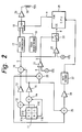
- Fig. 2 is a block diagram of a reproducing apparatus for reproducing a multi-layered disk.
- Numeral 11 denotes a quartered detector comprising four detectors (11A, 11B, 11C and 11D). The quartered detector 11 detects whether an irradiated laser beam is exactly focalized on the optical disk. Detection signals of the detectors 11A and 11C are supplied to an adder 12, and those of the detectors of 11B and 11D to an adder 14.
- the added signal (A+C) output from the adder 12 is supplied to a subtracter 16, adder 20 and adder 25 via an amplifier 13.
- the sum signal (B+D) output from the adder 14 is supplied to a subtracter 16, adder 20 and adder 25 via an amplifier 15.
- a focus error signal (signal c) sent to a phase compensation circuit 17 and one of input terminals of a comparator 22.
- a reference signal V2 Applied to the other terminal of the comparator 22 is a reference signal V2.
- the comparator 22 executes zero-cross detection, and outputs the detection signal to a switch 23 when the focus error signal is not exceeded by the reference signal V2.
- the focus error signal, phase-compensated by the phase compensation circuit 17, is supplied to one of selective terminals of a switch 18. Supplied to the other selective terminal of the switch 18 is a focus search drive voltage from a focus search drive circuit 19 having a predetermined characteristic.
- a focus search drive voltage from a focus search drive circuit 19 having a predetermined characteristic.
- the output signal of the phase compensation circuit 17 it is determined that focalization on the optical disk is established.
- the output signal of the focus search drive circuit 19 it is determined that the beam is not focalized on the optical disk.
- An object lens mounted in a pickup is moved by the signal output from the focus search drive circuit 19. In the initial state, the focus drive circuit 19 is selected by the switch 18.
- a reproduction RF signal (A+B+C+D) (signal a) output from the adder 20 is supplied to one of input terminals of a comparator 21. Applied to the other input terminal of the comparator 21 is a reference signal level V1. The comparator 21 compares the reproduction RF signal level with the reference signal level V1. When the reproduction RF signal level is not exceeded by the reference signal level V1, a focus OK signal (signal b) indicating focalization being proper is output to a switch 23 as a control signal. When the switch 23 is turned on, a zero-cross detection signal (signal d) output from the comparator 22 is supplied to a CPU 24. The CPU 24 detects the trailing edge of the zero-cross detection signal.
- the adder 25 generates a reproduction RF signal (A+B+C+D) and supplies it to a data decoder 27 via an amplifier 26.
- the signal decoded by the decoder 27 is output to the CPU 24 as a sub-code data.
- recorded on the sub-code R is the data indicating how many recording layers the optical disk has.
- Recorded on each sub-code S is the layer I.D. data indicating the ordinal number of the layer.
- the CPU 24 generates a focus ON signal (signal e) only at the trailing edge of the zero-cross detection signal.
- the focus ON signal is supplied to the switch 18 as a control signal to have the switch 18 select the phase compensation circuit 17.
- the signal selected by the switch 18 is sent through a drive amplifier 28 to a focus drive coil 29 having one end connected to ground.
- Figs. 3A, 3B, 3C, 3D and 3E are waveform diagrams of signals output from respective circuits in the optical disk reproducing apparatus.
- the reproduction RF signal (signal a) is supplied from the adder 20 to the comparator 21.
- the comparator 21 is also supplied with the reference signal V1 (see Fig. 3A). If the reproduction RF signal is not exceeded by the reference signal V1, the focus OK signal (signal b) (see Fig. 3B) output from the comparator 21 represents the high level (hereinafter called H level), and it is output to the switch 23.
- the switch 23 is turned on only during the focus OK signal being supplied.
- the focus error signal (signal c) output from the subtracter 16 and the reference signal V2 (see Fig. 3C).
- the signal through the switch 23 (zero-cross detection signal output from the comparator 22; signal d) is supplied to the CPU 24 (see Fig. 3D).
- CPU 24 generates the focus ON signal at the trailing edge of the focus zero-cross detection signal, and supplies it to the switch 18.
- the switch 18 selects the output signal of the phase compensation circuit 17.
- Focus search is started at time H.
- the focus ON signal is changed to H level at the trailing edge (time I) of the zero cross detection signal, and it is output from CPU 24 to the switch 18.
- time I the trailing edge
- focalization meets on the first recording layer of the optical disk loaded.
- the layer-number data recorded on the sub-code R of the first recording layer is read out to detect the number of recording layers of the optical disk.
- the focus OK signal is changed to the low level (hereinafter called L level). Accordingly, the focus ON signal is changed to L level. From the time on, focus search of the second recording layer is started.
- the focus ON signal is changed to H level at the trailing edge of the zero-cross detection signal, and it is supplied to the switch 18.
- layer data recorded on the sub-code S of the second recording layer is read out.
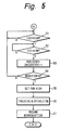
- Figs. 4 and 5 are a flow chart of a process for focalization on the second recording layer of the optical disk having three recording layers.
- the focus ON signal is changed to L level in step 41.
- step 42 and step 43 the state of the zero-cross detection signal is referred to. That is, it is determined whether the zero-cross signal has changed from H level to L level.
- the focus ON signal is changed to H level at the trailing edge of the zero-cross detection signal (step 44).
- focus servo control is executed on the first recording layer.
- step 45 after tracking for the first recording layer is turned ON, the spindle motor is activated. Thus the loaded optical disk is rotated in a predetermined direction.
- step 46 the layer-number data recorded on the sub-code R of the first layer is read out to detect the number of recording layers the optical disk has (in this example, the optical disk is recognized to have three recording layers).
- a command for example, "search of a chapter on the second layer" preliminarily input through a remote controller, or the like, is read (step 47), and the tracking and spindle motor are turned OFF (step 48).
- step 49 Since the command instructs access to the second recording layer in this example, "2" is stored in a register (for example, register A) in CPU (step 49). This is the number of occurrence of the zero-cross detection signal to be counted.
- the focus ON signal is changed to L level, focus search is started (step 50).
- step 51 and step 52 the state of the zero-cross detection signal is referred to. That is, it is determined whether the zero-cross detection signal has changed from H level to L level.
- the count number of the zero-cross signal is decremented (step 53).
- step 54 it is judged whether the count number of zero-cross detection signals has become zero.
- step 55 it is determined whether the zero cross-detection signal has been detected twice after the count number was set as 2. If it is judged that the zero-cross detection signal has not been detected twice, the process returns step 51. On the other hand, when it is judged that the zero-cross detection signal has been detected twice, the process goes to step 55.
- step 55 the focus ON signal is changed to H level.
- focalization onto the second recording layer In step 56, after tracking is adjusted, the optical disk is rotated in a predetermined direction by the spindle motor. Then the second recording layer is reproduced (step 57).
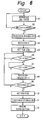
- Fig. 6 is a flow chart of a process for returning the focus to a proper recording layer from another recording layer to which it accidentally jumped. Such focus jump is caused by flaws, or the like, on the optical disk as explained before.
- step 61 the second recording layer is reproduced. If a focus jump occurred during this reproduction, the laser beam is focused to the first or second layer.
- step 62 it is judged whether the currently reproduced layer is the second layer or not. If it is the second layer, then the process returns to step 61. If it is not the second layer, then the process goes to step 63. In step 63, tracking and the spindle motor are inactivated.
- the register for example, register A in CPU stores "2". This value of the register is read out (step 64). After that, the focus ON signal is changed to L level, focus search is started (step 65). Then the object lens starts moving from the initial position. In step 66 and step 67, it is judged whether the zero-cross detection signal has changed from H level to L level. If the zero-cross detection signal is found to have changed to L level, the count number of the zero-cross detection signal stored in the register is decremented (step 68). In step 69, it is judged whether the count number stored in the register has changed to 0 or not.
- step 70 it is judged whether the zero-cross detection signal has been detected twice after the layer under current reproduction is found to be other than the second layer. If it is judged that the zero-cross detection signal has not been detected twice, the process returns to 66. On the other hand, if the zero-cross detection signal is found to have been detected twice, the process goes to step 70.
- step 70 the focus ON signal is changed to H level.
- focalization onto the second recording layer After tracking is adjusted (step 71), the optical disk is rotated in a predetermined direction by the spindle motor, and reproduction of the digital data recorded on the second recording layer is resumed (step 72).
- the optical disk has layer I.D. data each indicating the ordinal number of each recording layer and recorded on each recording layer, and has layer-number data indicating the number of recording layers and recorded on the first recording layer. It can be known, therefore, which layer is currently reproduced. Even when the focus jumps to a wrong layer due to a flaw, etc. on the disk, it can be immediately returned to a proper layer because the currently reproduced layer can be identified. Moreover, since the layer-number data and the layer I.D. data are known, focus search and focus jump can be executed reliably.
Landscapes
- Optical Recording Or Reproduction (AREA)
- Moving Of The Head For Recording And Reproducing By Optical Means (AREA)
- Holo Graphy (AREA)
- Electrochromic Elements, Electrophoresis, Or Variable Reflection Or Absorption Elements (AREA)
- Engine Equipment That Uses Special Cycles (AREA)
- Television Signal Processing For Recording (AREA)
- Optical Record Carriers And Manufacture Thereof (AREA)
Applications Claiming Priority (3)
| Application Number | Priority Date | Filing Date | Title |
|---|---|---|---|
| JP30697194 | 1994-11-16 | ||
| JP306971/94 | 1994-11-16 | ||
| JP6306971A JPH08147762A (ja) | 1994-11-16 | 1994-11-16 | 光ディスク及びその再生装置 |
Publications (3)
| Publication Number | Publication Date |
|---|---|
| EP0713217A2 true EP0713217A2 (de) | 1996-05-22 |
| EP0713217A3 EP0713217A3 (de) | 1996-08-07 |
| EP0713217B1 EP0713217B1 (de) | 2001-07-25 |
Family
ID=17963474
Family Applications (1)
| Application Number | Title | Priority Date | Filing Date |
|---|---|---|---|
| EP95308170A Expired - Lifetime EP0713217B1 (de) | 1994-11-16 | 1995-11-15 | Wiedergabe von optischen Platten |
Country Status (13)
| Country | Link |
|---|---|
| US (1) | US5793720A (de) |
| EP (1) | EP0713217B1 (de) |
| JP (1) | JPH08147762A (de) |
| KR (1) | KR100378243B1 (de) |
| CN (1) | CN1075652C (de) |
| AT (1) | ATE203621T1 (de) |
| AU (1) | AU708606B2 (de) |
| BR (1) | BR9505203A (de) |
| CA (1) | CA2162962C (de) |
| DE (1) | DE69521871T2 (de) |
| ES (1) | ES2158927T3 (de) |
| MY (1) | MY114108A (de) |
| TW (2) | TW287271B (de) |
Cited By (7)
| Publication number | Priority date | Publication date | Assignee | Title |
|---|---|---|---|---|
| WO1997005605A2 (en) * | 1995-07-31 | 1997-02-13 | Philips Electronics N.V. | Optical scanning apparatus for a multi-layer record carrier, including a focus control circuit |
| WO1997023872A1 (fr) * | 1995-12-21 | 1997-07-03 | Thomson-Csf | Support d'enregistrement/lecture optique d'informations et procede d'enregistrement |
| EP0811971A2 (de) * | 1996-06-06 | 1997-12-10 | Kabushiki Kaisha Kenwood | Optisches Plattengerät |
| EP1128370A2 (de) * | 2000-02-25 | 2001-08-29 | Mitsubishi Denki Kabushiki Kaisha | Fokussuchverfahren und optisches Plattengerät |
| WO2002037483A1 (fr) * | 2000-11-06 | 2002-05-10 | Matsushita Electric Industrial Co., Ltd. | Support d'enregistrement optique, procede et appareil de production de support d'enregistrement optique, logiciel et support correspondants |
| EP1262960A2 (de) * | 1997-10-16 | 2002-12-04 | Sony Corporation | Gerät zum abspielen von optischen Platten mit Mitteln gegen Kollision versehen , sowie Steuerungsverfahren für dieses Gerät |
| US7209431B2 (en) | 1994-12-19 | 2007-04-24 | Kononklijke Philps Electronics N.V. | Multilayer record carrier and device for scanning said carrier |
Families Citing this family (28)
| Publication number | Priority date | Publication date | Assignee | Title |
|---|---|---|---|---|
| DE69738507T2 (de) * | 1996-07-10 | 2008-06-12 | Hitachi, Ltd. | Verfahren und System zum Datenzugriff für einen optischen Plattenspieler |
| JPH10134360A (ja) * | 1996-10-29 | 1998-05-22 | Sony Corp | 再生装置および方法 |
| US20050058039A1 (en) * | 1997-01-16 | 2005-03-17 | Yasuo Kamatani | Multi-standard optical disk and method and apparatus of reading from and recording to the disk |
| US5956304A (en) * | 1997-08-15 | 1999-09-21 | Cirrus Logic, Inc. | Differential phase error detector using dual arm correlation for servo tracking in an optical disk storage device |
| US6064529A (en) * | 1998-07-02 | 2000-05-16 | Optiteck, Inc. | Spherical aberration correction using flying lens and method |
| US6111828A (en) * | 1999-01-12 | 2000-08-29 | Siros Technologies, Inc. | Focus error signal generation using confocally filtered detection |
| US6256271B1 (en) | 1999-01-12 | 2001-07-03 | Siros Technologies, Inc. | Focus error signal generation using two polarizers in confocal configuration |
| US6322933B1 (en) | 1999-01-12 | 2001-11-27 | Siros Technologies, Inc. | Volumetric track definition for data storage media used to record data by selective alteration of a format hologram |
| US6288986B1 (en) | 1999-01-12 | 2001-09-11 | Siros Technologies, Inc. | Focus error signal generation using a birefringent plate with confocal detection |
| US6269057B1 (en) | 1999-01-12 | 2001-07-31 | Siros Technologies, Inc. | Focus error signal generation using a birefringent lens with confocal detection |
| AU5704600A (en) * | 1999-06-28 | 2001-01-31 | Sony Corporation | Optical disk recording and/or reproducing device, and focusing servomechanism |
| US6322931B1 (en) | 1999-07-29 | 2001-11-27 | Siros Technologies, Inc. | Method and apparatus for optical data storage using non-linear heating by excited state absorption for the alteration of pre-formatted holographic gratings |
| US6310850B1 (en) | 1999-07-29 | 2001-10-30 | Siros Technologies, Inc. | Method and apparatus for optical data storage and/or retrieval by selective alteration of a holographic storage medium |
| US6512606B1 (en) | 1999-07-29 | 2003-01-28 | Siros Technologies, Inc. | Optical storage media and method for optical data storage via local changes in reflectivity of a format grating |
| WO2003010761A1 (en) * | 2001-07-26 | 2003-02-06 | Sony Corporation | Optical recording/reproducing apparatus, focusing method therefor, and optical disk recording medium |
| CN100353431C (zh) * | 2001-07-26 | 2007-12-05 | 索尼株式会社 | 光盘记录/再现装置、其聚焦方法、以及光盘记录介质 |
| JP2003248942A (ja) * | 2002-02-25 | 2003-09-05 | Funai Electric Co Ltd | 光ディスク装置 |
| US20050213467A1 (en) | 2002-12-17 | 2005-09-29 | Yoshihiro Noda | Optical recording medium, and recording/reading method and recording/reading apparatus for optical recording medium |
| JP2005032290A (ja) | 2003-07-07 | 2005-02-03 | Ricoh Co Ltd | 情報記録媒体及び光ディスク装置 |
| JP4424211B2 (ja) * | 2004-04-09 | 2010-03-03 | 日本ビクター株式会社 | 情報記録媒体の記録方法及び記録装置 |
| CN1981328B (zh) | 2004-07-05 | 2011-02-09 | 日本先锋公司 | 信息记录装置 |
| US8755258B2 (en) | 2005-02-16 | 2014-06-17 | Mitsubishi Electric Corporation | Optical disc and optical disc device |
| JP3812584B1 (ja) * | 2005-02-16 | 2006-08-23 | 三菱電機株式会社 | 光ディスク及び光ディスク装置 |
| CN101151665A (zh) * | 2005-03-31 | 2008-03-26 | 皇家飞利浦电子股份有限公司 | 一种用于从多层光学信息载体再现信息的方法 |
| JP2008123618A (ja) * | 2006-11-13 | 2008-05-29 | Kenwood Corp | 光ディスク再生装置、その球面収差補正値取得方法及びプログラム |
| JP2009181614A (ja) * | 2008-01-29 | 2009-08-13 | Sanyo Electric Co Ltd | 光ディスクおよび光ディスク装置 |
| JP5372864B2 (ja) * | 2009-08-18 | 2013-12-18 | パナソニック株式会社 | 多層光ディスクおよび光ディスク装置 |
| WO2013046256A1 (ja) * | 2011-09-28 | 2013-04-04 | 日立コンシューマエレクトロニクス株式会社 | 光ディスク並びに光ディスク装置及び記録方法並びに層判別方法 |
Citations (3)
| Publication number | Priority date | Publication date | Assignee | Title |
|---|---|---|---|---|
| EP0426409A2 (de) * | 1989-10-30 | 1991-05-08 | Matsushita Electric Industrial Co., Ltd. | Mehrlagige optische Platte |
| EP0496132A2 (de) * | 1990-12-21 | 1992-07-29 | Koninklijke Philips Electronics N.V. | Verfahren und Vorrichtung zum Beschreiben, Auslesen und Löschen eines Mehrflächen-Aufzeichnungsträgers auf optischem Wege, und für dieses Verfahren und diese Vorrichtung geeigneter Aufzeichnungsträger |
| EP0517490A2 (de) * | 1991-06-04 | 1992-12-09 | International Business Machines Corporation | Optisches Datenspeichersystem und -verfahren mit Mehrfachdatenoberfläche |
Family Cites Families (3)
| Publication number | Priority date | Publication date | Assignee | Title |
|---|---|---|---|---|
| JPS60226029A (ja) * | 1984-04-24 | 1985-11-11 | Sony Corp | 光学式デイスク・プレ−ヤ |
| JPH0276128A (ja) * | 1988-09-13 | 1990-03-15 | Pioneer Electron Corp | フォーカスサーボ引込み方法 |
| JPH04364229A (ja) * | 1990-11-01 | 1992-12-16 | Matsushita Electric Ind Co Ltd | 光方式記録再生方法および記録媒体、光方式記録再生装置 |
-
1994
- 1994-11-16 JP JP6306971A patent/JPH08147762A/ja active Pending
-
1995
- 1995-11-15 TW TW084112092A patent/TW287271B/zh not_active IP Right Cessation
- 1995-11-15 EP EP95308170A patent/EP0713217B1/de not_active Expired - Lifetime
- 1995-11-15 AU AU37873/95A patent/AU708606B2/en not_active Expired
- 1995-11-15 DE DE69521871T patent/DE69521871T2/de not_active Expired - Lifetime
- 1995-11-15 ES ES95308170T patent/ES2158927T3/es not_active Expired - Lifetime
- 1995-11-15 AT AT95308170T patent/ATE203621T1/de active
- 1995-11-15 CA CA002162962A patent/CA2162962C/en not_active Expired - Lifetime
- 1995-11-16 CN CN95120362A patent/CN1075652C/zh not_active Expired - Lifetime
- 1995-11-16 KR KR1019950041583A patent/KR100378243B1/ko not_active IP Right Cessation
- 1995-11-16 BR BR9505203A patent/BR9505203A/pt not_active IP Right Cessation
- 1995-11-16 MY MYPI95003475A patent/MY114108A/en unknown
-
1996
- 1996-11-13 US US08/748,414 patent/US5793720A/en not_active Expired - Lifetime
-
1998
- 1998-06-25 TW TW087210183U patent/TW387271U/zh not_active IP Right Cessation
Patent Citations (3)
| Publication number | Priority date | Publication date | Assignee | Title |
|---|---|---|---|---|
| EP0426409A2 (de) * | 1989-10-30 | 1991-05-08 | Matsushita Electric Industrial Co., Ltd. | Mehrlagige optische Platte |
| EP0496132A2 (de) * | 1990-12-21 | 1992-07-29 | Koninklijke Philips Electronics N.V. | Verfahren und Vorrichtung zum Beschreiben, Auslesen und Löschen eines Mehrflächen-Aufzeichnungsträgers auf optischem Wege, und für dieses Verfahren und diese Vorrichtung geeigneter Aufzeichnungsträger |
| EP0517490A2 (de) * | 1991-06-04 | 1992-12-09 | International Business Machines Corporation | Optisches Datenspeichersystem und -verfahren mit Mehrfachdatenoberfläche |
Cited By (15)
| Publication number | Priority date | Publication date | Assignee | Title |
|---|---|---|---|---|
| US7209431B2 (en) | 1994-12-19 | 2007-04-24 | Kononklijke Philps Electronics N.V. | Multilayer record carrier and device for scanning said carrier |
| WO1997005605A3 (en) * | 1995-07-31 | 1997-03-13 | Philips Electronics Nv | Optical scanning apparatus for a multi-layer record carrier, including a focus control circuit |
| US5757744A (en) * | 1995-07-31 | 1998-05-26 | U.S. Philips Corporation | Optical scanning apparatus for a multi-layer record carrier, including a focus control circuit |
| WO1997005605A2 (en) * | 1995-07-31 | 1997-02-13 | Philips Electronics N.V. | Optical scanning apparatus for a multi-layer record carrier, including a focus control circuit |
| WO1997023872A1 (fr) * | 1995-12-21 | 1997-07-03 | Thomson-Csf | Support d'enregistrement/lecture optique d'informations et procede d'enregistrement |
| EP0811971A2 (de) * | 1996-06-06 | 1997-12-10 | Kabushiki Kaisha Kenwood | Optisches Plattengerät |
| EP0811971A3 (de) * | 1996-06-06 | 1998-04-01 | Kabushiki Kaisha Kenwood | Optisches Plattengerät |
| EP1262960A3 (de) * | 1997-10-16 | 2004-10-27 | Sony Corporation | Gerät zum abspielen von optischen Platten mit Mitteln gegen Kollision versehen , sowie Steuerungsverfahren für dieses Gerät |
| EP1262960A2 (de) * | 1997-10-16 | 2002-12-04 | Sony Corporation | Gerät zum abspielen von optischen Platten mit Mitteln gegen Kollision versehen , sowie Steuerungsverfahren für dieses Gerät |
| EP1128370A2 (de) * | 2000-02-25 | 2001-08-29 | Mitsubishi Denki Kabushiki Kaisha | Fokussuchverfahren und optisches Plattengerät |
| US6633522B2 (en) | 2000-02-25 | 2003-10-14 | Mitsubishi Denki Kabushiki Kaisha | Focus pull-in method and optical disk device |
| EP1128370A3 (de) * | 2000-02-25 | 2003-04-09 | Mitsubishi Denki Kabushiki Kaisha | Fokussuchverfahren und optisches Plattengerät |
| WO2002037483A1 (fr) * | 2000-11-06 | 2002-05-10 | Matsushita Electric Industrial Co., Ltd. | Support d'enregistrement optique, procede et appareil de production de support d'enregistrement optique, logiciel et support correspondants |
| US7239601B2 (en) | 2000-11-06 | 2007-07-03 | Matsushita Electric Industrial Co., Ltd. | Optical recording medium, method of manufacturing optical recording medium, apparatus for manufacturing optical recording medium, program, and medium |
| CN100437773C (zh) * | 2000-11-06 | 2008-11-26 | 松下电器产业株式会社 | 光记录媒体制造方法和光记录媒体制造装置 |
Also Published As
| Publication number | Publication date |
|---|---|
| AU708606B2 (en) | 1999-08-05 |
| DE69521871D1 (de) | 2001-08-30 |
| CN1135634A (zh) | 1996-11-13 |
| EP0713217B1 (de) | 2001-07-25 |
| TW387271U (en) | 2000-04-11 |
| BR9505203A (pt) | 1997-09-16 |
| AU3787395A (en) | 1996-05-23 |
| JPH08147762A (ja) | 1996-06-07 |
| KR960019133A (ko) | 1996-06-17 |
| EP0713217A3 (de) | 1996-08-07 |
| TW287271B (de) | 1996-10-01 |
| DE69521871T2 (de) | 2002-04-04 |
| CA2162962A1 (en) | 1996-05-17 |
| US5793720A (en) | 1998-08-11 |
| ES2158927T3 (es) | 2001-09-16 |
| CN1075652C (zh) | 2001-11-28 |
| MY114108A (en) | 2002-08-30 |
| CA2162962C (en) | 2006-06-13 |
| KR100378243B1 (ko) | 2003-12-11 |
| ATE203621T1 (de) | 2001-08-15 |
Similar Documents
| Publication | Publication Date | Title |
|---|---|---|
| US5793720A (en) | Optical disk and reproducing apparatus including a focus search control device | |
| EP0294490B1 (de) | Eine optische platte diskriminierendes gerät | |
| KR0185953B1 (ko) | Dvd시스템의 dvd/cd 판별방법 | |
| EP0193961B1 (de) | Verfahren zum Auswählen von Informationen eines Plattenspielers | |
| US6744705B1 (en) | Optical disc recording and reproducing apparatus | |
| US4841505A (en) | Pickup position control method enabling restart of reproduction after interruption | |
| US5771214A (en) | Optical information recording/reproducing apparatus capable of detecting tracking and/or focusing error and method therefor | |
| US6674694B1 (en) | Light-pickup device applied to a recording and/or reproduction device for an optical disk inluding a detection circuit that generates a focus zero cross signal | |
| KR19980033407A (ko) | 재생 장치 및 재생 방법 | |
| US5442613A (en) | Optical information recording/reproduction apparatus to stop recording operation upon detecting error in access operation to target track | |
| US6021103A (en) | Device for recording to an optical disk by using a track descriptor block on the optical disk | |
| US7570550B2 (en) | Focus servo recovery processing method for optical disc device and optical disc device | |
| JPH09219056A (ja) | ディスク再生方法およびその装置 | |
| US6982935B2 (en) | Pause control for a media player with a movable pickup | |
| JP4033992B2 (ja) | 光ディスク再生装置 | |
| KR100396597B1 (ko) | 광기록재생기의 서보 제어 장치 및 방법 | |
| JP3782188B2 (ja) | 光ディスク再生システムのリトライ装置 | |
| KR100187837B1 (ko) | 광디스크재생시스템의 서보제어방법 | |
| JP2000182313A (ja) | 光ディスク再生装置及び光ディスクの種類を判別する方法 | |
| JPH05258383A (ja) | 光ヘッドのサーボ安定化方式 | |
| KR20000014134A (ko) | 광 디스크 시스템의 서보 구동장치 및 구동방법 | |
| JP3682223B2 (ja) | マルチビーム光ディスク装置及び光ビーム照射位置移動方法 | |
| JPH05266489A (ja) | 情報処理装置 | |
| KR19990080062A (ko) | 광픽업의 탐색모드에서 목표위치 이동방법 | |
| JPH07244863A (ja) | ディスク装置 |
Legal Events
| Date | Code | Title | Description |
|---|---|---|---|
| PUAI | Public reference made under article 153(3) epc to a published international application that has entered the european phase |
Free format text: ORIGINAL CODE: 0009012 |
|
| AK | Designated contracting states |
Kind code of ref document: A2 Designated state(s): AT DE ES FR GB IT NL |
|
| PUAL | Search report despatched |
Free format text: ORIGINAL CODE: 0009013 |
|
| AK | Designated contracting states |
Kind code of ref document: A3 Designated state(s): AT DE ES FR GB IT NL |
|
| 17P | Request for examination filed |
Effective date: 19970103 |
|
| 17Q | First examination report despatched |
Effective date: 19991027 |
|
| GRAG | Despatch of communication of intention to grant |
Free format text: ORIGINAL CODE: EPIDOS AGRA |
|
| RTI1 | Title (correction) |
Free format text: REPRODUCTION OF OPTICAL DISKS |
|
| RTI1 | Title (correction) |
Free format text: REPRODUCTION OF OPTICAL DISKS |
|
| GRAG | Despatch of communication of intention to grant |
Free format text: ORIGINAL CODE: EPIDOS AGRA |
|
| GRAH | Despatch of communication of intention to grant a patent |
Free format text: ORIGINAL CODE: EPIDOS IGRA |
|
| GRAH | Despatch of communication of intention to grant a patent |
Free format text: ORIGINAL CODE: EPIDOS IGRA |
|
| GRAA | (expected) grant |
Free format text: ORIGINAL CODE: 0009210 |
|
| AK | Designated contracting states |
Kind code of ref document: B1 Designated state(s): AT DE ES FR GB IT NL |
|
| REF | Corresponds to: |
Ref document number: 203621 Country of ref document: AT Date of ref document: 20010815 Kind code of ref document: T |
|
| REF | Corresponds to: |
Ref document number: 69521871 Country of ref document: DE Date of ref document: 20010830 |
|
| REG | Reference to a national code |
Ref country code: ES Ref legal event code: FG2A Ref document number: 2158927 Country of ref document: ES Kind code of ref document: T3 |
|
| ET | Fr: translation filed | ||
| REG | Reference to a national code |
Ref country code: GB Ref legal event code: IF02 |
|
| PLBE | No opposition filed within time limit |
Free format text: ORIGINAL CODE: 0009261 |
|
| STAA | Information on the status of an ep patent application or granted ep patent |
Free format text: STATUS: NO OPPOSITION FILED WITHIN TIME LIMIT |
|
| 26N | No opposition filed | ||
| REG | Reference to a national code |
Ref country code: GB Ref legal event code: 746 Effective date: 20120703 |
|
| REG | Reference to a national code |
Ref country code: DE Ref legal event code: R084 Ref document number: 69521871 Country of ref document: DE Effective date: 20120614 |
|
| PGFP | Annual fee paid to national office [announced via postgrant information from national office to epo] |
Ref country code: ES Payment date: 20141119 Year of fee payment: 20 Ref country code: DE Payment date: 20141119 Year of fee payment: 20 Ref country code: GB Payment date: 20141119 Year of fee payment: 20 Ref country code: FR Payment date: 20141119 Year of fee payment: 20 |
|
| PGFP | Annual fee paid to national office [announced via postgrant information from national office to epo] |
Ref country code: NL Payment date: 20141119 Year of fee payment: 20 Ref country code: AT Payment date: 20141120 Year of fee payment: 20 |
|
| PGFP | Annual fee paid to national office [announced via postgrant information from national office to epo] |
Ref country code: IT Payment date: 20141125 Year of fee payment: 20 |
|
| REG | Reference to a national code |
Ref country code: DE Ref legal event code: R071 Ref document number: 69521871 Country of ref document: DE |
|
| REG | Reference to a national code |
Ref country code: NL Ref legal event code: MK Effective date: 20151114 |
|
| REG | Reference to a national code |
Ref country code: GB Ref legal event code: PE20 Expiry date: 20151114 |
|
| REG | Reference to a national code |
Ref country code: AT Ref legal event code: MK07 Ref document number: 203621 Country of ref document: AT Kind code of ref document: T Effective date: 20151115 |
|
| PG25 | Lapsed in a contracting state [announced via postgrant information from national office to epo] |
Ref country code: GB Free format text: LAPSE BECAUSE OF EXPIRATION OF PROTECTION Effective date: 20151114 |
|
| REG | Reference to a national code |
Ref country code: ES Ref legal event code: FD2A Effective date: 20160226 |
|
| PG25 | Lapsed in a contracting state [announced via postgrant information from national office to epo] |
Ref country code: ES Free format text: LAPSE BECAUSE OF EXPIRATION OF PROTECTION Effective date: 20151116 |