EP0711690A2 - Unité d'entraînement à un moteur à combustion interne et un retardateur hydrodynamique - Google Patents
Unité d'entraînement à un moteur à combustion interne et un retardateur hydrodynamique Download PDFInfo
- Publication number
- EP0711690A2 EP0711690A2 EP95117556A EP95117556A EP0711690A2 EP 0711690 A2 EP0711690 A2 EP 0711690A2 EP 95117556 A EP95117556 A EP 95117556A EP 95117556 A EP95117556 A EP 95117556A EP 0711690 A2 EP0711690 A2 EP 0711690A2
- Authority
- EP
- European Patent Office
- Prior art keywords
- retarder
- fan
- crankshaft
- drive unit
- rotor
- Prior art date
- Legal status (The legal status is an assumption and is not a legal conclusion. Google has not performed a legal analysis and makes no representation as to the accuracy of the status listed.)
- Withdrawn
Links
Images


Classifications
-
- B—PERFORMING OPERATIONS; TRANSPORTING
- B60—VEHICLES IN GENERAL
- B60K—ARRANGEMENT OR MOUNTING OF PROPULSION UNITS OR OF TRANSMISSIONS IN VEHICLES; ARRANGEMENT OR MOUNTING OF PLURAL DIVERSE PRIME-MOVERS IN VEHICLES; AUXILIARY DRIVES FOR VEHICLES; INSTRUMENTATION OR DASHBOARDS FOR VEHICLES; ARRANGEMENTS IN CONNECTION WITH COOLING, AIR INTAKE, GAS EXHAUST OR FUEL SUPPLY OF PROPULSION UNITS IN VEHICLES
- B60K5/00—Arrangement or mounting of internal-combustion or jet-propulsion units
-
- F—MECHANICAL ENGINEERING; LIGHTING; HEATING; WEAPONS; BLASTING
- F01—MACHINES OR ENGINES IN GENERAL; ENGINE PLANTS IN GENERAL; STEAM ENGINES
- F01P—COOLING OF MACHINES OR ENGINES IN GENERAL; COOLING OF INTERNAL-COMBUSTION ENGINES
- F01P3/00—Liquid cooling
- F01P3/12—Arrangements for cooling other engine or machine parts
-
- B—PERFORMING OPERATIONS; TRANSPORTING
- B60—VEHICLES IN GENERAL
- B60T—VEHICLE BRAKE CONTROL SYSTEMS OR PARTS THEREOF; BRAKE CONTROL SYSTEMS OR PARTS THEREOF, IN GENERAL; ARRANGEMENT OF BRAKING ELEMENTS ON VEHICLES IN GENERAL; PORTABLE DEVICES FOR PREVENTING UNWANTED MOVEMENT OF VEHICLES; VEHICLE MODIFICATIONS TO FACILITATE COOLING OF BRAKES
- B60T1/00—Arrangements of braking elements, i.e. of those parts where braking effect occurs specially for vehicles
- B60T1/02—Arrangements of braking elements, i.e. of those parts where braking effect occurs specially for vehicles acting by retarding wheels
- B60T1/08—Arrangements of braking elements, i.e. of those parts where braking effect occurs specially for vehicles acting by retarding wheels using fluid or powdered medium
- B60T1/087—Arrangements of braking elements, i.e. of those parts where braking effect occurs specially for vehicles acting by retarding wheels using fluid or powdered medium in hydrodynamic, i.e. non-positive displacement, retarders
-
- F—MECHANICAL ENGINEERING; LIGHTING; HEATING; WEAPONS; BLASTING
- F02—COMBUSTION ENGINES; HOT-GAS OR COMBUSTION-PRODUCT ENGINE PLANTS
- F02B—INTERNAL-COMBUSTION PISTON ENGINES; COMBUSTION ENGINES IN GENERAL
- F02B67/00—Engines characterised by the arrangement of auxiliary apparatus not being otherwise provided for, e.g. the apparatus having different functions; Driving auxiliary apparatus from engines, not otherwise provided for
-
- F—MECHANICAL ENGINEERING; LIGHTING; HEATING; WEAPONS; BLASTING
- F16—ENGINEERING ELEMENTS AND UNITS; GENERAL MEASURES FOR PRODUCING AND MAINTAINING EFFECTIVE FUNCTIONING OF MACHINES OR INSTALLATIONS; THERMAL INSULATION IN GENERAL
- F16D—COUPLINGS FOR TRANSMITTING ROTATION; CLUTCHES; BRAKES
- F16D57/00—Liquid-resistance brakes; Brakes using the internal friction of fluids or fluid-like media, e.g. powders
- F16D57/02—Liquid-resistance brakes; Brakes using the internal friction of fluids or fluid-like media, e.g. powders with blades or like members braked by the fluid
-
- F—MECHANICAL ENGINEERING; LIGHTING; HEATING; WEAPONS; BLASTING
- F16—ENGINEERING ELEMENTS AND UNITS; GENERAL MEASURES FOR PRODUCING AND MAINTAINING EFFECTIVE FUNCTIONING OF MACHINES OR INSTALLATIONS; THERMAL INSULATION IN GENERAL
- F16D—COUPLINGS FOR TRANSMITTING ROTATION; CLUTCHES; BRAKES
- F16D57/00—Liquid-resistance brakes; Brakes using the internal friction of fluids or fluid-like media, e.g. powders
- F16D57/04—Liquid-resistance brakes; Brakes using the internal friction of fluids or fluid-like media, e.g. powders with blades causing a directed flow, e.g. Föttinger type
-
- F—MECHANICAL ENGINEERING; LIGHTING; HEATING; WEAPONS; BLASTING
- F16—ENGINEERING ELEMENTS AND UNITS; GENERAL MEASURES FOR PRODUCING AND MAINTAINING EFFECTIVE FUNCTIONING OF MACHINES OR INSTALLATIONS; THERMAL INSULATION IN GENERAL
- F16D—COUPLINGS FOR TRANSMITTING ROTATION; CLUTCHES; BRAKES
- F16D65/00—Parts or details
- F16D65/78—Features relating to cooling
-
- F—MECHANICAL ENGINEERING; LIGHTING; HEATING; WEAPONS; BLASTING
- F01—MACHINES OR ENGINES IN GENERAL; ENGINE PLANTS IN GENERAL; STEAM ENGINES
- F01P—COOLING OF MACHINES OR ENGINES IN GENERAL; COOLING OF INTERNAL-COMBUSTION ENGINES
- F01P2060/00—Cooling circuits using auxiliaries
- F01P2060/06—Retarder
-
- F—MECHANICAL ENGINEERING; LIGHTING; HEATING; WEAPONS; BLASTING
- F01—MACHINES OR ENGINES IN GENERAL; ENGINE PLANTS IN GENERAL; STEAM ENGINES
- F01P—COOLING OF MACHINES OR ENGINES IN GENERAL; COOLING OF INTERNAL-COMBUSTION ENGINES
- F01P5/00—Pumping cooling-air or liquid coolants
- F01P5/02—Pumping cooling-air; Arrangements of cooling-air pumps, e.g. fans or blowers
- F01P5/04—Pump-driving arrangements
Definitions
- the invention relates to a drive unit, in particular for a motor vehicle, according to the preamble of claim 1.
- retarders are mainly used to absorb the kinetic braking energy that occurs especially when braking from high driving speed (adaptive braking) and to convert it into heat, but retarders are also well suited for required sustained braking performance, for example at a constant speed of 30 km / h and with a gradient of 7%. Oil is usually used as the operating fluid. The heat transferred to the operating fluid in the retarder must be supplied to the coolant or the ambient air using a special heat exchanger.
- the retarder known from US Pat. No. 3,720,372 (document 2) is integrated with the drive motor, permanently connected to the crankshaft and always flowed through by the coolant of the cooling device.
- the rotor of the retarder serves as a circulation pump instead of a separate coolant pump.
- the purpose of this device is to heat the coolant by means of the retarder in order to heat the passenger interior.
- This purpose is also served by a control device arranged on the retarder, which merely guides the distribution of the coolant through the cooler in a bypass line as a function of its temperature.
- a retarder is also known, which is connected via a switchable clutch to the crankshaft of the drive motor and the drive wheels of the vehicle.
- the task of the retarder is not to absorb and convert the vehicle's high kinetic braking energy into heat.
- the retarder is operated exclusively as a heater, whereby the heating power should be controlled taking into account an available drive power.
- the engine coolant is also the operating fluid for the retarder.
- a retarder known from DE-AS 1 946 167 (US Pat. No. 3,650,358) is driven by the crankshaft of an internal combustion engine, the coolant of which also serves as operating fluid for the retarder.
- the advantage of this mode of operation is that the heat generated is developed directly in the coolant supplied to the cooler and a heat exchanger between two liquids is unnecessary.
- the rotor is mounted with a roller bearing and the seal between the frame and the rotor shaft is carried out with two lip seals.
- the invention has for its object to design a drive unit according to the preamble of claim 1 such that the axial length and the weight are less than in the known drive units.
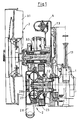
- crankshaft 1 In Figure 1, only a few parts of the engine are shown, including the crankshaft 1, a connecting rod 1.1 and a shaft journal 1.2 screwed on the end face to the crankshaft 1 and a crankcase 1.3.
- the retarder 2 has a rotor blade wheel 2.1 and a stator blade wheel 2.2.
- the rotor blade wheel is overhung on the shaft journal 1.2.
- the retarder has a housing which is constructed from a bell 2.3 surrounding the rotor blade wheel and also from a cover body 2.4.
- the shaft journal 1.2 also carries a damping device 2.5 which is connected to the shaft journal 1.2 in a rotationally fixed manner.
- the fan 3 is driven by the crankshaft 1 of the engine, specifically via a gearwheel set shown only partially here. As you can see, the fan shaft 3.2 runs parallel to the shaft journal 1.2.
- the arrangement is such that the retarder 2 practically fills the entire space, which is limited by the end face of the crankcase 1.3 facing the retarder or by the gear set that drives the fan 3, further by the fan shaft 3.2 and finally by the trailing edge the fan wheel 3.1.
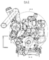
- the retarder 2 with the lid body 2.4 is located in the plan view according to FIG. 2 within the flight circle of the Fan wheel 3.1. The space is thus optimally used.
- Retarder 2 Since Retarder 2 is located directly in front of the engine (cold side of the engine cooling), you can use the water mass that is between the retarder inlet and the radiator, the engine lubricating oil mass and the metal mass of the cooling system including the engine for capacitive energy consumption. As a result, the retarder has a larger capacity. The braking power can generate more energy in the short term than the cooler can permanently transmit.
- the design and arrangement of the lid body contribute to the compactness of the construction.
- the entire drive unit is easy to maintain, because by removing the fan wheel 3.1 and possibly the cover body 2.4 there is free access to all the crucial parts.
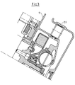
- FIGS 3 and 4 again show the crucial components, insofar as they relate to the structure of the retarder.
- the cover body 2.4 is connected to the corresponding pipeline connections by means of plug connections.
- Stator blade wheel 2.2 and cover body 2.4 can be formed in one piece, that is to say they consist of a single piece.
- the rotor 2.1 of the retarder 2 is preferably mounted on the fly; it is therefore carried by the crankshaft bearing.
- the inventors have provided an intermediate body 4 in a particularly clever manner. This is located between the crankcase 1.3 and the fan 3. It is mounted on the crankcase 1.3 and connects directly to the cover body 2.4. It carries a variety of elements. In any case, he carries the complete fan 3 together with its shaft 3.2 with impeller 3.1. It also centers the housing 2.3 and 2.4 of the retarder 2. It can also carry other units, such as thermostats.
- FIG. 5 The outlines of the intermediate body can be seen in FIG. 5 - indicated there by dash-dotted lines. From this one can see in detail the inlet opening 4.9 for the coolant to the engine, and also the outlet opening 4.10 from the crankcase. You can also see a tension pulley 4.11 for the V-belt of the auxiliary machines. Furthermore, articulation points 4.12 for a support bracket 4.13 for auxiliary units can be seen. At the top right in FIG. 5 there is an outlet nozzle 4.8 for coolant flowing to the vehicle radiator.
- Figure 6 shows the environment in the area of the fan shaft 3.2.
- the intermediate body 4 the crankcase 1.3, a thermostat housing 4.1 and the Thermostats 4.2, also a channel 4.4 as a short circuit connection for liquid to the retarder 2.
- FIG. 8 the section is also placed in a different plane than in FIG. 6.
- FIG. 9 a housing part 4.5 as a gear drive termination, furthermore the drive gears 4.7 for driving the fan 3, the fan shaft 3.2 and the plug connection 2.9.
Landscapes
- Engineering & Computer Science (AREA)
- General Engineering & Computer Science (AREA)
- Mechanical Engineering (AREA)
- Chemical & Material Sciences (AREA)
- Combustion & Propulsion (AREA)
- Transportation (AREA)
- Physics & Mathematics (AREA)
- Fluid Mechanics (AREA)
- Cylinder Crankcases Of Internal Combustion Engines (AREA)
- Braking Arrangements (AREA)
Applications Claiming Priority (2)
| Application Number | Priority Date | Filing Date | Title |
|---|---|---|---|
| DE4440165A DE4440165C2 (de) | 1994-11-10 | 1994-11-10 | Antriebseinheit mit einer Brennkraftmaschine und einem hydrodynamischen Retarder |
| DE4440165 | 1994-11-10 |
Publications (2)
| Publication Number | Publication Date |
|---|---|
| EP0711690A2 true EP0711690A2 (fr) | 1996-05-15 |
| EP0711690A3 EP0711690A3 (fr) | 1997-08-06 |
Family
ID=6532973
Family Applications (1)
| Application Number | Title | Priority Date | Filing Date |
|---|---|---|---|
| EP95117556A Withdrawn EP0711690A3 (fr) | 1994-11-10 | 1995-11-08 | Unité d'entraînement à un moteur à combustion interne et un retardateur hydrodynamique |
Country Status (9)
| Country | Link |
|---|---|
| US (1) | US5613472A (fr) |
| EP (1) | EP0711690A3 (fr) |
| JP (1) | JP3980086B2 (fr) |
| KR (1) | KR960017238A (fr) |
| BR (1) | BR9504931A (fr) |
| CZ (1) | CZ285043B6 (fr) |
| DE (1) | DE4440165C2 (fr) |
| HU (1) | HUT76756A (fr) |
| RU (1) | RU2148512C1 (fr) |
Families Citing this family (9)
| Publication number | Priority date | Publication date | Assignee | Title |
|---|---|---|---|---|
| DE19623680C2 (de) | 1996-06-14 | 1998-03-19 | Voith Turbo Kg | Retarder |
| DE19623679C5 (de) * | 1996-06-14 | 2006-05-24 | Voith Turbo Gmbh & Co. Kg | Antriebs-Baugruppe mit einem Retarder und einem Wärmetauscher |
| CA2474415A1 (fr) * | 2004-07-15 | 2006-01-15 | Gerald Hayes | Refroidisseur auxiliere pour un moteur situe dans un building |
| DE102005051221B3 (de) * | 2005-10-26 | 2007-04-12 | Voith Turbo Gmbh & Co. Kg | Arbeitsmediumanschluss einer hydrodynamischen Strömungsmaschine |
| CN103485871B (zh) * | 2012-06-12 | 2015-08-19 | 安徽华菱汽车有限公司 | 汽车及其发动机 |
| CN104533589A (zh) * | 2014-12-27 | 2015-04-22 | 广西玉柴机器股份有限公司 | 一种柴油机风扇支承板及其安装方法 |
| FR3083386B1 (fr) * | 2018-06-28 | 2021-05-14 | Telma | Ensemble ralentisseur electromagnetique et generatrice et vehicule comportant un tel ensemble |
| CN113958630B (zh) * | 2021-09-08 | 2024-03-08 | 中国北方车辆研究所 | 一种机械液力复合缓速制动装置 |
| US11746693B2 (en) | 2021-12-01 | 2023-09-05 | Smith Power Products, Inc. | Natural gas engine |
Citations (4)
| Publication number | Priority date | Publication date | Assignee | Title |
|---|---|---|---|---|
| DE1946167A1 (de) | 1968-09-17 | 1970-05-14 | Labavia | Bremse fuer Personenkraftfahrzeuge |
| US3720372A (en) | 1971-12-09 | 1973-03-13 | Gen Motors Corp | Means for rapidly heating interior of a motor vehicle |
| DE3301560C1 (de) | 1983-01-19 | 1984-04-05 | Daimler-Benz Ag, 7000 Stuttgart | Steuerung der Heizleistung einer hydrodynamischen Bremse |
| DE3713580C1 (en) | 1987-04-23 | 1988-11-10 | Voith Turbo Kg | Drive system with a hydrodynamic retarder |
Family Cites Families (4)
| Publication number | Priority date | Publication date | Assignee | Title |
|---|---|---|---|---|
| US3490567A (en) * | 1968-06-12 | 1970-01-20 | Caterpillar Tractor Co | Engine with hydrodynamic retarder |
| FR2230236A5 (fr) * | 1973-05-14 | 1974-12-13 | Labavia | |
| SE428192B (sv) * | 1979-11-19 | 1983-06-13 | Volvo Ab | Anordning vid motorfordon for momentoverforing |
| JPH01105025A (ja) * | 1987-10-14 | 1989-04-21 | Tokyo Buhin Kogyo Kk | エンジン制動装置 |
-
1994
- 1994-11-10 DE DE4440165A patent/DE4440165C2/de not_active Expired - Lifetime
-
1995
- 1995-11-07 US US08/554,488 patent/US5613472A/en not_active Expired - Lifetime
- 1995-11-08 KR KR1019950040304A patent/KR960017238A/ko not_active Application Discontinuation
- 1995-11-08 HU HU9503204A patent/HUT76756A/hu unknown
- 1995-11-08 EP EP95117556A patent/EP0711690A3/fr not_active Withdrawn
- 1995-11-09 RU RU95119425A patent/RU2148512C1/ru not_active IP Right Cessation
- 1995-11-09 BR BR9504931A patent/BR9504931A/pt not_active IP Right Cessation
- 1995-11-09 CZ CZ952959A patent/CZ285043B6/cs unknown
- 1995-11-10 JP JP31758095A patent/JP3980086B2/ja not_active Expired - Lifetime
Patent Citations (4)
| Publication number | Priority date | Publication date | Assignee | Title |
|---|---|---|---|---|
| DE1946167A1 (de) | 1968-09-17 | 1970-05-14 | Labavia | Bremse fuer Personenkraftfahrzeuge |
| US3720372A (en) | 1971-12-09 | 1973-03-13 | Gen Motors Corp | Means for rapidly heating interior of a motor vehicle |
| DE3301560C1 (de) | 1983-01-19 | 1984-04-05 | Daimler-Benz Ag, 7000 Stuttgart | Steuerung der Heizleistung einer hydrodynamischen Bremse |
| DE3713580C1 (en) | 1987-04-23 | 1988-11-10 | Voith Turbo Kg | Drive system with a hydrodynamic retarder |
Also Published As
| Publication number | Publication date |
|---|---|
| DE4440165C2 (de) | 1997-02-20 |
| RU2148512C1 (ru) | 2000-05-10 |
| CZ285043B6 (cs) | 1999-05-12 |
| KR960017238A (ko) | 1996-06-17 |
| HU9503204D0 (en) | 1995-12-28 |
| JP3980086B2 (ja) | 2007-09-19 |
| BR9504931A (pt) | 1997-09-02 |
| CZ295995A3 (en) | 1996-05-15 |
| EP0711690A3 (fr) | 1997-08-06 |
| HUT76756A (en) | 1997-11-28 |
| US5613472A (en) | 1997-03-25 |
| JPH08225068A (ja) | 1996-09-03 |
| DE4440165A1 (de) | 1995-07-06 |
Similar Documents
| Publication | Publication Date | Title |
|---|---|---|
| EP0707140B1 (fr) | Unité d'entraínement à moteur et ralentisseur hydraulique | |
| DE19509417A1 (de) | Antriebseinheit | |
| EP0722867B1 (fr) | Unité d'entraínement avec un moteur à combustion interne et un ralentisseur hydrodynamique. | |
| DE4408349C2 (de) | Antriebseinheit mit einem Motor und einem Retarder | |
| DE4440164C2 (de) | Antriebseinheit mit einer Brennkraftmaschine und einem hydrodynamischen Retarder | |
| DE4440163C2 (de) | Antriebseinheit mit einer Brennkraftmaschine und einem hydrodynamischen Retarder | |
| DE4211896A1 (de) | Gehäusedeckel für eine Brennkraftmaschine | |
| DE4440165C2 (de) | Antriebseinheit mit einer Brennkraftmaschine und einem hydrodynamischen Retarder | |
| EP0835993B1 (fr) | Unité de propulsion comportant un moteur, une boíte de vitesses et une pompe à eau | |
| EP0718166A2 (fr) | Unité d'entraînement à un moteur à combustion interne et un ralentisseur hydrodynamique | |
| DE4440162C2 (de) | Antriebseinheit mit einer Brennkraftmaschine und einem hydrodynamischen Retarder | |
| DE69628261T2 (de) | Wärmegenerator mittels viskoser Fluide mit einem länglichen Rotorelement | |
| EP0716966B1 (fr) | Unité d'entraínement | |
| EP1081003B1 (fr) | Ensemble pour moteur à combustion interne | |
| EP0794326A1 (fr) | Unité d'entraînement à moteur et ralentisseur hydraulique | |
| DE19641450B4 (de) | Antriebseinheit, insbesondere für ein Kraftfahrzeug | |
| DE19544189C2 (de) | Antriebseinheit | |
| EP0803418A1 (fr) | Unité d'entraînement avec un moteur et un ralentisseur | |
| DE19751529C2 (de) | Fluidreibungswärme nutzende Heizvorrichtung | |
| EP0835992B1 (fr) | Groupe motopropulseur, notamment pour un véhicule automobile | |
| DE10034398A1 (de) | Kühleinrichtung für eine Brennkraftmaschine | |
| DE19733750C2 (de) | Heizeinrichtung mit einem viskosen Fluid | |
| DE594875C (de) | Kuehleinrichtung fuer Brennkraftmaschinen mit zwanglaeufigem Kuehloelkreislauf | |
| EP0803416A1 (fr) | Unité d'entraînement à moteur et ralentisseur | |
| DE102011115580A1 (de) | Stromerzeugungsaggregat |
Legal Events
| Date | Code | Title | Description |
|---|---|---|---|
| PUAI | Public reference made under article 153(3) epc to a published international application that has entered the european phase |
Free format text: ORIGINAL CODE: 0009012 |
|
| AK | Designated contracting states |
Kind code of ref document: A2 Designated state(s): AT DE ES FR GB IT NL SE |
|
| PUAL | Search report despatched |
Free format text: ORIGINAL CODE: 0009013 |
|
| AK | Designated contracting states |
Kind code of ref document: A3 Designated state(s): AT DE ES FR GB IT NL SE |
|
| RHK1 | Main classification (correction) |
Ipc: B60T 1/087 |
|
| 17P | Request for examination filed |
Effective date: 19971029 |
|
| RAP1 | Party data changed (applicant data changed or rights of an application transferred) |
Owner name: VOITH TURBO BETEILIGUNGS GMBH |
|
| STAA | Information on the status of an ep patent application or granted ep patent |
Free format text: STATUS: THE APPLICATION HAS BEEN WITHDRAWN |
|
| 17Q | First examination report despatched |
Effective date: 19990311 |
|
| 18W | Application withdrawn |
Withdrawal date: 19990403 |