EP0803418A1 - Unité d'entraînement avec un moteur et un ralentisseur - Google Patents
Unité d'entraînement avec un moteur et un ralentisseur Download PDFInfo
- Publication number
- EP0803418A1 EP0803418A1 EP97104906A EP97104906A EP0803418A1 EP 0803418 A1 EP0803418 A1 EP 0803418A1 EP 97104906 A EP97104906 A EP 97104906A EP 97104906 A EP97104906 A EP 97104906A EP 0803418 A1 EP0803418 A1 EP 0803418A1
- Authority
- EP
- European Patent Office
- Prior art keywords
- retarder
- working medium
- drive unit
- valve
- coolant
- Prior art date
- Legal status (The legal status is an assumption and is not a legal conclusion. Google has not performed a legal analysis and makes no representation as to the accuracy of the status listed.)
- Ceased
Links
- 239000002826 coolant Substances 0.000 claims abstract description 14
- 238000001816 cooling Methods 0.000 claims abstract description 4
- 238000002485 combustion reaction Methods 0.000 claims description 2
- 238000009423 ventilation Methods 0.000 description 3
- 239000012530 fluid Substances 0.000 description 2
- 239000007788 liquid Substances 0.000 description 2
- 238000005086 pumping Methods 0.000 description 2
- 230000008094 contradictory effect Effects 0.000 description 1
- 230000000694 effects Effects 0.000 description 1
- 238000010438 heat treatment Methods 0.000 description 1
- 239000000463 material Substances 0.000 description 1
- XLYOFNOQVPJJNP-UHFFFAOYSA-N water Substances O XLYOFNOQVPJJNP-UHFFFAOYSA-N 0.000 description 1
Images
Classifications
-
- B—PERFORMING OPERATIONS; TRANSPORTING
- B60—VEHICLES IN GENERAL
- B60T—VEHICLE BRAKE CONTROL SYSTEMS OR PARTS THEREOF; BRAKE CONTROL SYSTEMS OR PARTS THEREOF, IN GENERAL; ARRANGEMENT OF BRAKING ELEMENTS ON VEHICLES IN GENERAL; PORTABLE DEVICES FOR PREVENTING UNWANTED MOVEMENT OF VEHICLES; VEHICLE MODIFICATIONS TO FACILITATE COOLING OF BRAKES
- B60T10/00—Control or regulation for continuous braking making use of fluid or powdered medium, e.g. for use when descending a long slope
- B60T10/02—Control or regulation for continuous braking making use of fluid or powdered medium, e.g. for use when descending a long slope with hydrodynamic brake
-
- B—PERFORMING OPERATIONS; TRANSPORTING
- B60—VEHICLES IN GENERAL
- B60T—VEHICLE BRAKE CONTROL SYSTEMS OR PARTS THEREOF; BRAKE CONTROL SYSTEMS OR PARTS THEREOF, IN GENERAL; ARRANGEMENT OF BRAKING ELEMENTS ON VEHICLES IN GENERAL; PORTABLE DEVICES FOR PREVENTING UNWANTED MOVEMENT OF VEHICLES; VEHICLE MODIFICATIONS TO FACILITATE COOLING OF BRAKES
- B60T1/00—Arrangements of braking elements, i.e. of those parts where braking effect occurs specially for vehicles
- B60T1/02—Arrangements of braking elements, i.e. of those parts where braking effect occurs specially for vehicles acting by retarding wheels
- B60T1/08—Arrangements of braking elements, i.e. of those parts where braking effect occurs specially for vehicles acting by retarding wheels using fluid or powdered medium
- B60T1/087—Arrangements of braking elements, i.e. of those parts where braking effect occurs specially for vehicles acting by retarding wheels using fluid or powdered medium in hydrodynamic, i.e. non-positive displacement, retarders
-
- F—MECHANICAL ENGINEERING; LIGHTING; HEATING; WEAPONS; BLASTING
- F01—MACHINES OR ENGINES IN GENERAL; ENGINE PLANTS IN GENERAL; STEAM ENGINES
- F01P—COOLING OF MACHINES OR ENGINES IN GENERAL; COOLING OF INTERNAL-COMBUSTION ENGINES
- F01P2060/00—Cooling circuits using auxiliaries
- F01P2060/06—Retarder
Definitions
- the invention relates to a drive unit with a motor, a retarder and a pump.
- a drive unit is known from DE 37 13 580 C1.
- the retarder serves to circulate the coolant of the vehicle cooling system in the coolant circuit both in normal traction operation and in continuous braking operation (“water pump retarder”).
- This retarder is controlled by a suitable valve arrangement in such a way that it can also perform braking work if necessary.
- the power consumption should be as low as possible, while with the "Braking” function it should be as high as possible.
- the technical requirements are therefore very contradictory. As a result, the "Pump" function does not work effectively enough, because it consumes too much power.
- the retarder and pump can be designed in such a way that the functions are optimally fulfilled.
- a system takes up a lot of space. This is disadvantageous because the space in vehicles is very cramped at the point in question.
- the retarder known from US Pat. No. 3,720,372 is integrated with the drive motor, permanently connected to the crankshaft and always flowed through by the coolant of the cooling device.
- the rotor of the retarder serves as a circulation pump instead of a separate coolant pump.
- the purpose of this device is to heat the coolant by means of the retarder, to warm the passenger interior.
- This purpose is also served by a control device arranged on the retarder, which merely guides the distribution of the coolant through the cooler in a bypass line as a function of its temperature.
- a retarder is also known from DE 33 01 560 C1, which is connected to the crankshaft of the drive motor and the drive wheels of the vehicle via a switchable clutch.
- the task of the retarder is not to absorb and convert the vehicle's high kinetic braking energy into heat.
- the retarder is operated exclusively as a heater, whereby the heating power should be controlled taking into account an available drive power.
- the engine coolant is also the operating fluid for the retarder.
- a retarder known from DE-AS 19 46 167 is connected directly to the crankshaft of an internal combustion engine, the coolant of which also serves as operating fluid for the retarder.
- the advantage of this mode of operation is that the heat generated is developed directly in the coolant supplied to the cooler and a heat exchanger between two liquids is unnecessary.
- EP 0 707 140 A1 describes a drive unit with a motor and a hydrodynamic retarder.
- a pump impeller is provided, which is arranged axially to the rotor blade wheel of the retarder.
- the invention has for its object to design a drive unit of the type described in such a way that ventilation losses are minimized and that the retarder works optimally in braking operation, i.e. that the braking behavior is steady and reproducible.
- the valve mentioned in claim 1 is closed in non-braking operation. Since the connecting line between the operating material container and the retarder opens into the hydrodynamic center of the retarder, in which a negative pressure prevails, the section of the connecting line between the named valve and the hydrodynamic center is evacuated; the rest of the working medium is minimized from the hydrodynamic center and throughout the retarder work area. Therefore, the power consumption during non-braking operation is minimized.
- the valve mentioned in the connecting line is opened.
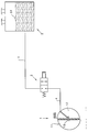
- a brake system with a hydrodynamic retarder 1, a valve 2 and a working medium container 3 can be seen in a schematic representation.
- the retarder 1 has a rotor blade wheel 1.1 and a stator blade wheel 1.2. Both form a working space with each other, which has a hydrodynamic center 1.3.
- a line 4 is located between the retarder 1 and valve 2.
- a line 5 is located between the valve 2 and the working medium container 3.
- the line 4 leads to the hydrodynamic center 1.3, in the present case passing through the stator blade wheel 1.2. It would also be possible to establish a connection via the circuit gap between rotor blade wheel 1.1 and stator blade wheel 1.2. A connection through the retarder impeller would also be conceivable.
- the line 5 opens in the present case under the level 3.1 of the working medium in the container 3rd
- valve 2 For braking operation, the valve 2 is brought into such a position that a conductive connection between the retarder 1 and the working medium container 3 is again established, and thus equipotential bonding. As a result, a reproducible and optimally controllable braking torque is generated in each braking phase.
Landscapes
- Engineering & Computer Science (AREA)
- Physics & Mathematics (AREA)
- Fluid Mechanics (AREA)
- Transportation (AREA)
- Mechanical Engineering (AREA)
- Braking Arrangements (AREA)
- Transmission Of Braking Force In Braking Systems (AREA)
Applications Claiming Priority (2)
| Application Number | Priority Date | Filing Date | Title |
|---|---|---|---|
| DE19616427 | 1996-04-25 | ||
| DE19616427A DE19616427C2 (de) | 1996-04-25 | 1996-04-25 | Antriebseinheit mit einem Motor und einem Retarder |
Publications (1)
| Publication Number | Publication Date |
|---|---|
| EP0803418A1 true EP0803418A1 (fr) | 1997-10-29 |
Family
ID=7792347
Family Applications (1)
| Application Number | Title | Priority Date | Filing Date |
|---|---|---|---|
| EP97104906A Ceased EP0803418A1 (fr) | 1996-04-25 | 1997-03-22 | Unité d'entraînement avec un moteur et un ralentisseur |
Country Status (4)
| Country | Link |
|---|---|
| US (1) | US6223718B1 (fr) |
| EP (1) | EP0803418A1 (fr) |
| JP (1) | JPH1061688A (fr) |
| DE (1) | DE19616427C2 (fr) |
Families Citing this family (6)
| Publication number | Priority date | Publication date | Assignee | Title |
|---|---|---|---|---|
| DE19833892B4 (de) * | 1998-07-28 | 2008-04-30 | Zf Friedrichshafen Ag | Hydrodynamischer Retarder für ein Kraftfahrzeug |
| DE10118856A1 (de) * | 2001-04-18 | 2002-10-24 | Zahnradfabrik Friedrichshafen | Bremsanlage mit einem Retarder |
| DE10242736A1 (de) * | 2002-09-13 | 2004-03-18 | Voith Turbo Gmbh & Co. Kg | Antriebseinheit mit einem Retarder |
| DE102013001657A1 (de) | 2013-01-31 | 2014-07-31 | Man Truck & Bus Ag | Kühlkreislauf für ein Kraftfahrzeug mit einem hydrodynamischen Retarder |
| DE102018122337A1 (de) * | 2018-09-13 | 2020-03-19 | Voith Patent Gmbh | Hydrodynamischer Retarder |
| US11746693B2 (en) | 2021-12-01 | 2023-09-05 | Smith Power Products, Inc. | Natural gas engine |
Citations (8)
| Publication number | Priority date | Publication date | Assignee | Title |
|---|---|---|---|---|
| US2750009A (en) * | 1951-11-17 | 1956-06-12 | Foote Bros Gear And Machine Co | Hydro-kinetic braking systems |
| US3051273A (en) * | 1959-07-15 | 1962-08-28 | Fiat Spa | Hydraulic brake |
| GB1007421A (en) * | 1961-01-24 | 1965-10-13 | Automotive Prod Co Ltd | Improvements in and relating to braking devices |
| DE1946167A1 (de) * | 1968-09-17 | 1970-05-14 | Labavia | Bremse fuer Personenkraftfahrzeuge |
| US3720372A (en) * | 1971-12-09 | 1973-03-13 | Gen Motors Corp | Means for rapidly heating interior of a motor vehicle |
| DE3301560C1 (de) * | 1983-01-19 | 1984-04-05 | Daimler-Benz Ag, 7000 Stuttgart | Steuerung der Heizleistung einer hydrodynamischen Bremse |
| DE3713580C1 (en) * | 1987-04-23 | 1988-11-10 | Voith Turbo Kg | Drive system with a hydrodynamic retarder |
| EP0707140A1 (fr) * | 1994-10-12 | 1996-04-17 | VOITH TURBO GMBH & CO. KG | Unité d'entraînement à moteur et ralentisseur hydraulique |
Family Cites Families (20)
| Publication number | Priority date | Publication date | Assignee | Title |
|---|---|---|---|---|
| US3860097A (en) | 1970-07-24 | 1975-01-14 | Parmac Inc | Individualized stator and rotor for hydromatic brakes |
| GB1484011A (en) | 1973-08-09 | 1977-08-24 | Fluidrive Eng Co Ltd | Fluid couplings |
| GB1464372A (en) | 1974-05-14 | 1977-02-09 | Hawker Siddeley Dynamics Ltd | Hydrokinetic braking systems |
| DE2462058C3 (de) * | 1974-10-12 | 1981-12-24 | M.A.N. Maschinenfabrik Augsburg-Nürnberg AG, 8000 München | Wandleraggregat für Verbrennungskraftmaschinen |
| DE2618073C3 (de) | 1976-04-24 | 1980-09-11 | Voith Getriebe Kg, 7920 Heidenheim | Fahrzeugantrieb, insbesondere für ein Schienenfahrzeug |
| JPS5853249Y2 (ja) | 1976-07-28 | 1983-12-03 | 日産自動車株式会社 | 自動車用パ−クロツク装置 |
| DE2710927A1 (de) | 1977-03-12 | 1978-09-14 | Daimler Benz Ag | Hydrodynamischer retarder fuer fahrzeuge, insbesondere fuer kraftfahrzeuge |
| DE2927582C2 (de) | 1979-07-07 | 1982-09-09 | Voith Getriebe Kg, 7920 Heidenheim | Hydrodynamische Bremse |
| DE3042017A1 (de) | 1980-11-07 | 1982-06-24 | Daimler-Benz Ag, 7000 Stuttgart | Retarder fuer fahrzeuge, mit wenigstens einem inneren hydrodynamischen arbeitskreislauf |
| DE3113408C1 (de) | 1981-04-03 | 1982-10-07 | Voith-Turbo Gmbh & Co Kg, 7180 Crailsheim | Hydrodynamische Bremse |
| DE3535494A1 (de) | 1985-10-04 | 1987-04-16 | Voith Gmbh J M | Hydrodynamischer retarder |
| DE3545660C1 (de) | 1985-12-21 | 1987-06-25 | Voith Turbo Kg | Hydrodynamischer Stroemungskreislauf mit einer Einrichtung zur Reduktion der Luftventilationsleistung |
| JPH01105025A (ja) * | 1987-10-14 | 1989-04-21 | Tokyo Buhin Kogyo Kk | エンジン制動装置 |
| JPH01182643A (ja) | 1988-01-12 | 1989-07-20 | Nifco Inc | 回転ダンパー |
| US4836341A (en) | 1988-06-27 | 1989-06-06 | General Motors Corporation | Control system for a hydraulic retarder |
| JP2816489B2 (ja) | 1990-04-27 | 1998-10-27 | 曙ブレーキ工業株式会社 | リターダ制御装置 |
| DE4010970C2 (de) | 1990-04-05 | 1996-05-30 | Voith Turbo Kg | Hydrodynamischer Retarder |
| JPH05131848A (ja) * | 1991-11-15 | 1993-05-28 | Toyota Motor Corp | ハイブリツド車の駆動システム制御装置 |
| US5255733A (en) * | 1992-08-10 | 1993-10-26 | Ford Motor Company | Hybird vehicle cooling system |
| DE4408349C2 (de) | 1994-03-11 | 1995-08-31 | Voith Turbo Kg | Antriebseinheit mit einem Motor und einem Retarder |
-
1996
- 1996-04-25 DE DE19616427A patent/DE19616427C2/de not_active Expired - Fee Related
-
1997
- 1997-03-22 EP EP97104906A patent/EP0803418A1/fr not_active Ceased
- 1997-04-24 JP JP9107625A patent/JPH1061688A/ja active Pending
- 1997-04-24 US US08/842,262 patent/US6223718B1/en not_active Expired - Fee Related
Patent Citations (8)
| Publication number | Priority date | Publication date | Assignee | Title |
|---|---|---|---|---|
| US2750009A (en) * | 1951-11-17 | 1956-06-12 | Foote Bros Gear And Machine Co | Hydro-kinetic braking systems |
| US3051273A (en) * | 1959-07-15 | 1962-08-28 | Fiat Spa | Hydraulic brake |
| GB1007421A (en) * | 1961-01-24 | 1965-10-13 | Automotive Prod Co Ltd | Improvements in and relating to braking devices |
| DE1946167A1 (de) * | 1968-09-17 | 1970-05-14 | Labavia | Bremse fuer Personenkraftfahrzeuge |
| US3720372A (en) * | 1971-12-09 | 1973-03-13 | Gen Motors Corp | Means for rapidly heating interior of a motor vehicle |
| DE3301560C1 (de) * | 1983-01-19 | 1984-04-05 | Daimler-Benz Ag, 7000 Stuttgart | Steuerung der Heizleistung einer hydrodynamischen Bremse |
| DE3713580C1 (en) * | 1987-04-23 | 1988-11-10 | Voith Turbo Kg | Drive system with a hydrodynamic retarder |
| EP0707140A1 (fr) * | 1994-10-12 | 1996-04-17 | VOITH TURBO GMBH & CO. KG | Unité d'entraînement à moteur et ralentisseur hydraulique |
Also Published As
| Publication number | Publication date |
|---|---|
| JPH1061688A (ja) | 1998-03-06 |
| DE19616427A1 (de) | 1997-05-28 |
| DE19616427C2 (de) | 1997-08-28 |
| US6223718B1 (en) | 2001-05-01 |
Similar Documents
| Publication | Publication Date | Title |
|---|---|---|
| EP0707140B1 (fr) | Unité d'entraínement à moteur et ralentisseur hydraulique | |
| DE3713580C1 (en) | Drive system with a hydrodynamic retarder | |
| DE4408349C2 (de) | Antriebseinheit mit einem Motor und einem Retarder | |
| DE10242736A1 (de) | Antriebseinheit mit einem Retarder | |
| AT503361A1 (de) | Antrieb | |
| DE4420841A1 (de) | Heizvorrichtung für Kraftfahrzeuge | |
| EP1603782B1 (fr) | Entrainement de vehicule a moteur a ralentisseur a eau | |
| EP0711692B1 (fr) | Unité d'entraínement avec un moteur à combustion interne et un ralentisseur hydrodynamique | |
| EP0718166B1 (fr) | Unité d'entraínement à un moteur à combustion interne et un ralentisseur hydrodynamique | |
| WO2009015957A1 (fr) | Pompe à liquide | |
| EP1646771A1 (fr) | Circuit de refroidissement de vehicule automobile comprenant une pompe et un ralentisseur | |
| DE19616425C1 (de) | Antriebseinheit mit einem Motor und einem Retarder | |
| DE19609150A1 (de) | Antriebseinheit mit einem Motor und einem Retarder | |
| EP0722867B1 (fr) | Unité d'entraínement avec un moteur à combustion interne et un ralentisseur hydrodynamique. | |
| DE19616427C2 (de) | Antriebseinheit mit einem Motor und einem Retarder | |
| DE4440165C2 (de) | Antriebseinheit mit einer Brennkraftmaschine und einem hydrodynamischen Retarder | |
| DE102020207028A1 (de) | Pumpeneinheit | |
| EP0794326A1 (fr) | Unité d'entraînement à moteur et ralentisseur hydraulique | |
| EP0711691A1 (fr) | Unité d'entraînement avec un moteur à combustion interne et un ralentisseur hydrodynamique | |
| DE19934621B4 (de) | Kreislaufsystem eines Retarders | |
| EP0716966A2 (fr) | Unité d'entraînement | |
| DE19616426C1 (de) | Antriebseinheit mit einem Motor und einem Retarder | |
| EP0711693A1 (fr) | Unité d'entraînement avec un moteur à combustion interne et un ralentisseur hydrodynamique | |
| DE10054078B4 (de) | Antriebsanlage für ein Fahrzeug | |
| EP0803416A1 (fr) | Unité d'entraînement à moteur et ralentisseur |
Legal Events
| Date | Code | Title | Description |
|---|---|---|---|
| PUAI | Public reference made under article 153(3) epc to a published international application that has entered the european phase |
Free format text: ORIGINAL CODE: 0009012 |
|
| AK | Designated contracting states |
Kind code of ref document: A1 Designated state(s): DE FR GB IT SE |
|
| 17P | Request for examination filed |
Effective date: 19980314 |
|
| 17Q | First examination report despatched |
Effective date: 20000323 |
|
| STAA | Information on the status of an ep patent application or granted ep patent |
Free format text: STATUS: THE APPLICATION HAS BEEN REFUSED |
|
| 18R | Application refused |
Effective date: 20010131 |