EP0803418A1 - Drive unit with an engine and a retarder - Google Patents
Drive unit with an engine and a retarder Download PDFInfo
- Publication number
- EP0803418A1 EP0803418A1 EP97104906A EP97104906A EP0803418A1 EP 0803418 A1 EP0803418 A1 EP 0803418A1 EP 97104906 A EP97104906 A EP 97104906A EP 97104906 A EP97104906 A EP 97104906A EP 0803418 A1 EP0803418 A1 EP 0803418A1
- Authority
- EP
- European Patent Office
- Prior art keywords
- retarder
- working medium
- drive unit
- valve
- coolant
- Prior art date
- Legal status (The legal status is an assumption and is not a legal conclusion. Google has not performed a legal analysis and makes no representation as to the accuracy of the status listed.)
- Ceased
Links
- 239000002826 coolant Substances 0.000 claims abstract description 14
- 238000001816 cooling Methods 0.000 claims abstract description 4
- 238000002485 combustion reaction Methods 0.000 claims description 2
- 238000009423 ventilation Methods 0.000 description 3
- 239000012530 fluid Substances 0.000 description 2
- 239000007788 liquid Substances 0.000 description 2
- 238000005086 pumping Methods 0.000 description 2
- 230000008094 contradictory effect Effects 0.000 description 1
- 230000000694 effects Effects 0.000 description 1
- 238000010438 heat treatment Methods 0.000 description 1
- 239000000463 material Substances 0.000 description 1
- XLYOFNOQVPJJNP-UHFFFAOYSA-N water Substances O XLYOFNOQVPJJNP-UHFFFAOYSA-N 0.000 description 1
Images
Classifications
-
- B—PERFORMING OPERATIONS; TRANSPORTING
- B60—VEHICLES IN GENERAL
- B60T—VEHICLE BRAKE CONTROL SYSTEMS OR PARTS THEREOF; BRAKE CONTROL SYSTEMS OR PARTS THEREOF, IN GENERAL; ARRANGEMENT OF BRAKING ELEMENTS ON VEHICLES IN GENERAL; PORTABLE DEVICES FOR PREVENTING UNWANTED MOVEMENT OF VEHICLES; VEHICLE MODIFICATIONS TO FACILITATE COOLING OF BRAKES
- B60T10/00—Control or regulation for continuous braking making use of fluid or powdered medium, e.g. for use when descending a long slope
- B60T10/02—Control or regulation for continuous braking making use of fluid or powdered medium, e.g. for use when descending a long slope with hydrodynamic brake
-
- B—PERFORMING OPERATIONS; TRANSPORTING
- B60—VEHICLES IN GENERAL
- B60T—VEHICLE BRAKE CONTROL SYSTEMS OR PARTS THEREOF; BRAKE CONTROL SYSTEMS OR PARTS THEREOF, IN GENERAL; ARRANGEMENT OF BRAKING ELEMENTS ON VEHICLES IN GENERAL; PORTABLE DEVICES FOR PREVENTING UNWANTED MOVEMENT OF VEHICLES; VEHICLE MODIFICATIONS TO FACILITATE COOLING OF BRAKES
- B60T1/00—Arrangements of braking elements, i.e. of those parts where braking effect occurs specially for vehicles
- B60T1/02—Arrangements of braking elements, i.e. of those parts where braking effect occurs specially for vehicles acting by retarding wheels
- B60T1/08—Arrangements of braking elements, i.e. of those parts where braking effect occurs specially for vehicles acting by retarding wheels using fluid or powdered medium
- B60T1/087—Arrangements of braking elements, i.e. of those parts where braking effect occurs specially for vehicles acting by retarding wheels using fluid or powdered medium in hydrodynamic, i.e. non-positive displacement, retarders
-
- F—MECHANICAL ENGINEERING; LIGHTING; HEATING; WEAPONS; BLASTING
- F01—MACHINES OR ENGINES IN GENERAL; ENGINE PLANTS IN GENERAL; STEAM ENGINES
- F01P—COOLING OF MACHINES OR ENGINES IN GENERAL; COOLING OF INTERNAL-COMBUSTION ENGINES
- F01P2060/00—Cooling circuits using auxiliaries
- F01P2060/06—Retarder
Definitions
- the invention relates to a drive unit with a motor, a retarder and a pump.
- a drive unit is known from DE 37 13 580 C1.
- the retarder serves to circulate the coolant of the vehicle cooling system in the coolant circuit both in normal traction operation and in continuous braking operation (“water pump retarder”).
- This retarder is controlled by a suitable valve arrangement in such a way that it can also perform braking work if necessary.
- the power consumption should be as low as possible, while with the "Braking” function it should be as high as possible.
- the technical requirements are therefore very contradictory. As a result, the "Pump" function does not work effectively enough, because it consumes too much power.
- the retarder and pump can be designed in such a way that the functions are optimally fulfilled.
- a system takes up a lot of space. This is disadvantageous because the space in vehicles is very cramped at the point in question.
- the retarder known from US Pat. No. 3,720,372 is integrated with the drive motor, permanently connected to the crankshaft and always flowed through by the coolant of the cooling device.
- the rotor of the retarder serves as a circulation pump instead of a separate coolant pump.
- the purpose of this device is to heat the coolant by means of the retarder, to warm the passenger interior.
- This purpose is also served by a control device arranged on the retarder, which merely guides the distribution of the coolant through the cooler in a bypass line as a function of its temperature.
- a retarder is also known from DE 33 01 560 C1, which is connected to the crankshaft of the drive motor and the drive wheels of the vehicle via a switchable clutch.
- the task of the retarder is not to absorb and convert the vehicle's high kinetic braking energy into heat.
- the retarder is operated exclusively as a heater, whereby the heating power should be controlled taking into account an available drive power.
- the engine coolant is also the operating fluid for the retarder.
- a retarder known from DE-AS 19 46 167 is connected directly to the crankshaft of an internal combustion engine, the coolant of which also serves as operating fluid for the retarder.
- the advantage of this mode of operation is that the heat generated is developed directly in the coolant supplied to the cooler and a heat exchanger between two liquids is unnecessary.
- EP 0 707 140 A1 describes a drive unit with a motor and a hydrodynamic retarder.
- a pump impeller is provided, which is arranged axially to the rotor blade wheel of the retarder.
- the invention has for its object to design a drive unit of the type described in such a way that ventilation losses are minimized and that the retarder works optimally in braking operation, i.e. that the braking behavior is steady and reproducible.
- the valve mentioned in claim 1 is closed in non-braking operation. Since the connecting line between the operating material container and the retarder opens into the hydrodynamic center of the retarder, in which a negative pressure prevails, the section of the connecting line between the named valve and the hydrodynamic center is evacuated; the rest of the working medium is minimized from the hydrodynamic center and throughout the retarder work area. Therefore, the power consumption during non-braking operation is minimized.
- the valve mentioned in the connecting line is opened.
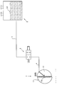
- a brake system with a hydrodynamic retarder 1, a valve 2 and a working medium container 3 can be seen in a schematic representation.
- the retarder 1 has a rotor blade wheel 1.1 and a stator blade wheel 1.2. Both form a working space with each other, which has a hydrodynamic center 1.3.
- a line 4 is located between the retarder 1 and valve 2.
- a line 5 is located between the valve 2 and the working medium container 3.
- the line 4 leads to the hydrodynamic center 1.3, in the present case passing through the stator blade wheel 1.2. It would also be possible to establish a connection via the circuit gap between rotor blade wheel 1.1 and stator blade wheel 1.2. A connection through the retarder impeller would also be conceivable.
- the line 5 opens in the present case under the level 3.1 of the working medium in the container 3rd
- valve 2 For braking operation, the valve 2 is brought into such a position that a conductive connection between the retarder 1 and the working medium container 3 is again established, and thus equipotential bonding. As a result, a reproducible and optimally controllable braking torque is generated in each braking phase.
Landscapes
- Engineering & Computer Science (AREA)
- Physics & Mathematics (AREA)
- Fluid Mechanics (AREA)
- Transportation (AREA)
- Mechanical Engineering (AREA)
- Braking Arrangements (AREA)
- Transmission Of Braking Force In Braking Systems (AREA)
Abstract
Die Erfindung betrifft eine Antriebseinheit mit einem hydrodynamischen Retarder ; der Retarder umfaßt ein Rotorschaufelrad und ein Statorschaufelrad, sowie einen diese beiden umschließende Wand; einen Kühlmittelkreislauf, dessen Kühlmittel zugleich Arbeitsmittel des Retarders ist; es ist ein Arbeitsmediumbehälter vorgesehen, der in den Kühlkreislauf geschaltet ist; zwischen Arbeitsmediumbehälter und dem hydrodynamischen Zentrum des Retarders ist eine Verbindungsleitung geschaltet; in der Verbindungsleitung befindet sich ein Ventil. <IMAGE>The invention relates to a drive unit with a hydrodynamic retarder; the retarder comprises a rotor blade wheel and a stator blade wheel, and also a wall surrounding these two; a coolant circuit, the coolant of which is also the working medium of the retarder; a working medium container is provided which is connected to the cooling circuit; a connecting line is connected between the working medium container and the hydrodynamic center of the retarder; There is a valve in the connecting line. <IMAGE>
Description
Die Erfindung betrifft eine Antriebseinheit mit einem Motor, einem Retarder und einer Pumpe. Eine solche Antriebseinheit ist aus DE 37 13 580 C1 bekannt geworden.The invention relates to a drive unit with a motor, a retarder and a pump. Such a drive unit is known from DE 37 13 580 C1.
Bei dieser bekannten Antriebseinheit dient der Retarder dazu, im Kühlmittelkreislauf das Kühlmittel der Fahrzeug-Kühlanlage sowohl im normalen Traktionsbetrieb als auch im Dauerbremsbetrieb umzuwälzen ("Wasserpumpen-Retarder"). Dabei wird dieser Retarder durch eine geeignete Ventilanordnung derart gesteuert, daß er im Bedarfsfalle auch Bremsarbeit leisten kann. Bei der Funktion "Pumpen" soll die Leistungsaufnahme möglichst gering sein, während sie bei der Funktion "Bremsen" möglichst hoch sein soll. Die technischen Anforderungen sind somit sehr gegensätzlich. Dies führt dazu, daß die Funktion "Pumpen" nicht effektiv genug arbeitet, weil nämlich hierbei zu viel Leistung aufgenommen wird.In this known drive unit, the retarder serves to circulate the coolant of the vehicle cooling system in the coolant circuit both in normal traction operation and in continuous braking operation (“water pump retarder”). This retarder is controlled by a suitable valve arrangement in such a way that it can also perform braking work if necessary. With the "Pump" function, the power consumption should be as low as possible, while with the "Braking" function it should be as high as possible. The technical requirements are therefore very contradictory. As a result, the "Pump" function does not work effectively enough, because it consumes too much power.
Trennt man hingegen die beiden Funktionen baulich, indem man außer dem Retarder eine separate Pumpe vorsieht, so lassen sich zwar Retarder und Pumpe derart auslegen, daß die Funktionen optimal erfüllt werden. Jedoch hat ein solches System einen hohen Raumbedarf. Dies ist nachteilig, da der Raum in Fahrzeugen gerade an der betreffenden Stelle sehr beengt ist.However, if you separate the two functions structurally by providing a separate pump in addition to the retarder, the retarder and pump can be designed in such a way that the functions are optimally fulfilled. However, such a system takes up a lot of space. This is disadvantageous because the space in vehicles is very cramped at the point in question.
Der Vollständigkeit halber sollen noch die folgenden Dokumente erwähnt werden:For the sake of completeness, the following documents should be mentioned:
Der aus der US 3 720 372 bekannte Retarder ist mit dem Antriebsmotor integriert, dauernd mit der Kurbelwelle verbunden und stets vom Kühlmittel der Kühleinrichtung durchströmt. Dabei dient der Rotor des Retarders als Umwälzpumpe anstelle einer gesonderten Kühlmittelpumpe. Der Zweck dieser Einrichtung besteht darin, mittels des Retarders das Kühlmittel aufzuheizen, um den Fahrgast-Innenraum zu erwärmen. Diesem Zweck dient auch eine am Retarder angeordnete Steuereinrichtung, die lediglich die Verteilung des Kühlmittels in Abhängigkeit von dessen Temperatur in einer Bypaß-Leitung durch den Kühler leitet.The retarder known from US Pat. No. 3,720,372 is integrated with the drive motor, permanently connected to the crankshaft and always flowed through by the coolant of the cooling device. The rotor of the retarder serves as a circulation pump instead of a separate coolant pump. The purpose of this device is to heat the coolant by means of the retarder, to warm the passenger interior. This purpose is also served by a control device arranged on the retarder, which merely guides the distribution of the coolant through the cooler in a bypass line as a function of its temperature.
Aus der DE 33 01 560 C1 ist ferner ein Retarder bekannt, der über eine schaltbare Kupplung mit der Kurbelwelle des Antriebsmotors und den Treibrädern des Fahrzeuges verbunden ist. Die Aufgabe des Retarders ist jedoch nicht die Aufnahme und Umsetzung hoher kinetischer Bremsenergie des Fahrzeuges in Wärme. Der Retarder wird ausschließlich als Heizgerät betrieben, wobei die Heizleistung unter Berücksichtigung einer zur Verfügung stehenden Antriebsleistung gesteuert werden soll. Das Kühlmittel des Motors ist gleichzeitig die Betriebsflüssigkeit des Retarders.A retarder is also known from DE 33 01 560 C1, which is connected to the crankshaft of the drive motor and the drive wheels of the vehicle via a switchable clutch. However, the task of the retarder is not to absorb and convert the vehicle's high kinetic braking energy into heat. The retarder is operated exclusively as a heater, whereby the heating power should be controlled taking into account an available drive power. The engine coolant is also the operating fluid for the retarder.
Ein aus der DE-AS 19 46 167 bekannter Retarder ist direkt mit der Kurbelwelle einer Verbrennungskraftmaschine verbunden, deren Kühlmittel auch als Betriebsflüssigkeit für den Retarder dient. Der Vorteil dieser Betriebsweise liegt darin, daß die anfallende Wärme unmittelbar in dem dem Kühler zugeleiteten Kühlmittel entwickelt wird und ein Wärmetauscher zwischen zwei Flüssigkeiten entbehrlich ist.A retarder known from DE-AS 19 46 167 is connected directly to the crankshaft of an internal combustion engine, the coolant of which also serves as operating fluid for the retarder. The advantage of this mode of operation is that the heat generated is developed directly in the coolant supplied to the cooler and a heat exchanger between two liquids is unnecessary.
EP 0 707 140 A1 beschreibt eine Antriebseinheit mit einem Motor und einem hydrodynamischen Retarder. Dabei ist zum Fördern des Kühlmittels ein Pumpenlaufrad vorgesehen, das axial zum Rotorschaufelrad des Retarders angeordnet ist.EP 0 707 140 A1 describes a drive unit with a motor and a hydrodynamic retarder. For pumping the coolant, a pump impeller is provided, which is arranged axially to the rotor blade wheel of the retarder.
Bei den bisher bekannten Retardern tritt im Nicht-Bremsbetrieb eine gewisse Verlustleistung auf. Der Retarder ist nämlich im Nicht-Bremsbetrieb mit Luft gefüllt, außerdem auch mit einem Rest des Arbeitsmediums. Dies führt zu Ventilationsverlusten.With the previously known retarders, a certain power loss occurs in non-braking operation. This is because the retarder is filled with air in non-braking mode and also with a remainder of the working medium. This leads to ventilation losses.
Der Erfindung liegt die Aufgabe zugrunde, eine Antriebseinheit der eingangs beschriebenen Art derart zu gestalten, daß Ventilationsverluste minimiert werden und daß der Retarder im Bremsbetrieb optimal arbeitet, d.h. daß das Bremsverhalten stetig und reproduzierbar ist.The invention has for its object to design a drive unit of the type described in such a way that ventilation losses are minimized and that the retarder works optimally in braking operation, i.e. that the braking behavior is steady and reproducible.
Diese Aufgabe wird durch die Merkmale von Anspruch 1 gelöst.This object is solved by the features of claim 1.
Das im Anspruch 1 genannte Ventil wird im Nicht-Bremsbetrieb geschlossen. Da die Verbindungsleitung zwischen Betriebsmittelbehälter und Retarder im hydrodynamischen Zentrum des Retarders mündet, in dem ein Unterdruck herrscht, wird der Abschnitt der Verbindungsleitung zwischen dem genannten Ventil und dem hydrodynamischen Zentrum evakuiert; aus dem hydrodynamischen Zentrum und im gesamten Retarder-Arbeitsraum wird der Rest an Arbeitsmedium minimiert. Deswegen wird die Leistungsaufnahme während des Nicht-Bremsbetriebes minimiert.The valve mentioned in claim 1 is closed in non-braking operation. Since the connecting line between the operating material container and the retarder opens into the hydrodynamic center of the retarder, in which a negative pressure prevails, the section of the connecting line between the named valve and the hydrodynamic center is evacuated; the rest of the working medium is minimized from the hydrodynamic center and throughout the retarder work area. Therefore, the power consumption during non-braking operation is minimized.
Beim Bremsbetrieb wird das genannte, in der Verbindungsleitung befindliche Ventil geöffnet. Dadurch, daß eine leitende Verbindung zwischen dem Arbeitsmediumbehälter und dem hydrodynamischen Zentrum des Retarders hergestellt ist, kann der Retarder sofort und sehr rasch mit der notwendigen Menge des Arbeitsmediums gefüllt werden, so daß die Bremswirkung ebenso schnell eintreten kann.During braking operation, the valve mentioned in the connecting line is opened. The fact that a conductive connection between the working medium container and the hydrodynamic center of the retarder is made, the retarder can be filled immediately and very quickly with the necessary amount of working medium, so that the braking effect can occur just as quickly.
Die Erfindung ist anhand der Zeichnung näher erläutert. Man erkennt in schematischer Darstellung ein Bremssystem mit einem hydrodynamischen Retarder 1, einem Ventil 2 und einem Arbeitsmediumbehälter 3. Der Retarder 1 weist ein Rotorschaufelrad 1.1 und ein Statorschaufelrad 1.2 auf. Beide bilden einen Arbeitsraum miteinander, der ein hydrodynamisches Zentrum 1.3 aufweist.The invention is explained in more detail with reference to the drawing. A brake system with a hydrodynamic retarder 1, a
Die drei Aggregate sind durch Leitungen miteinander verbunden. Zwischen Retarder 1 und Ventil 2 befindet sich eine Leitung 4. Zwischen Ventil 2 und Arbeitsmediumbehälter 3 befindet sich eine Leitung 5. Die Leitung 4 führt bis zum hydrodynamischen Zentrum 1.3, wobei sie im vorliegenden Falle durch das Statorschaufelrad 1.2 hindurchgeführt ist. Auch wäre es möglich, einen Anschluß über den Kreislaufspalt zwischen Rotorschaufelrad 1.1 und Statorschaufelrad 1.2 herzustellen. Ebenfalls wäre ein Anschluß durch das Retarderschaufelrad denkbar.The three units are connected by cables. A
Die Leitung 5 mündet im vorliegenden Falle unter dem Spiegel 3.1 des Arbeitsmediums im Behälter 3.The
Um im sogenannten Pumpbetrieb, d.h. in den Bremspausen, die Verlustleistung niedrig zu halten, muß die Restmenge der im Arbeitsraum vorhandenen Flüssigkeit minimiert werden. Dies geschieht gemäß der Erfindung dadurch, daß die leitende Verbindung zwischen dem Arbeitsmediumbehälter 3 und dem hydrodynamischen Zentrum 1.3 abgesperrt wird. Dies geschieht durch eine entsprechende Stellung des Ventils 2.0. Auch im Pumpbetrieb läuft das Rotorschaufelrad 1.1 weiter um. Hierdurch wird Arbeitsmedium aus dem Arbeitsraum gefördert. Aufgrund der genannten Stellung des Ventils 2.0 kann kein weiteres Arbeitsmedium nachströmen. Im Arbeitsraum entsteht daher ein Unterdruck, so daß auch nur eine verringerte Luftmenge im Arbeitsraum des Retarders 1 vorhanden ist. Deshalb werden die Ventilationsverluste miniminiert.In order to operate in the so-called pump mode, i.e. in the brake breaks to keep the power loss low, the remaining amount of liquid present in the work area must be minimized. This is done according to the invention in that the conductive connection between the working medium container 3 and the hydrodynamic center 1.3 is shut off. This is done by setting the valve 2.0 accordingly. The rotor blade wheel 1.1 continues to rotate even in pumping operation. As a result, working medium is conveyed out of the work area. Due to the position of the valve 2.0, no further working medium can flow in. A negative pressure therefore arises in the work area, so that only a reduced amount of air is present in the work area of the retarder 1. Therefore the ventilation losses are minimized.
Für den Bremsbetrieb wird das Ventil 2 in eine solche Position gebracht, daß wieder eine leitende Verbindung zwischen Retarder 1 und Arbeitsmediumbehälter 3 hergestellt wird, und damit ein Potentialausgleich. Hierdurch wird in jeder Bremsphase ein reproduzierbares und optimal regelbares Bremsmoment erzeugt.For braking operation, the
Claims (3)
Applications Claiming Priority (2)
| Application Number | Priority Date | Filing Date | Title |
|---|---|---|---|
| DE19616427A DE19616427C2 (en) | 1996-04-25 | 1996-04-25 | Drive unit with a motor and a retarder |
| DE19616427 | 1996-04-25 |
Publications (1)
| Publication Number | Publication Date |
|---|---|
| EP0803418A1 true EP0803418A1 (en) | 1997-10-29 |
Family
ID=7792347
Family Applications (1)
| Application Number | Title | Priority Date | Filing Date |
|---|---|---|---|
| EP97104906A Ceased EP0803418A1 (en) | 1996-04-25 | 1997-03-22 | Drive unit with an engine and a retarder |
Country Status (4)
| Country | Link |
|---|---|
| US (1) | US6223718B1 (en) |
| EP (1) | EP0803418A1 (en) |
| JP (1) | JPH1061688A (en) |
| DE (1) | DE19616427C2 (en) |
Families Citing this family (6)
| Publication number | Priority date | Publication date | Assignee | Title |
|---|---|---|---|---|
| DE19833892B4 (en) * | 1998-07-28 | 2008-04-30 | Zf Friedrichshafen Ag | Hydrodynamic retarder for a motor vehicle |
| DE10118856A1 (en) * | 2001-04-18 | 2002-10-24 | Zahnradfabrik Friedrichshafen | Brake system with a retarder |
| DE10242736A1 (en) * | 2002-09-13 | 2004-03-18 | Voith Turbo Gmbh & Co. Kg | Hydrodynamic speed reduction system for motor vehicles, has a sliding rotator and variable gap to the stator and emptying of residual fluid |
| DE102013001657A1 (en) | 2013-01-31 | 2014-07-31 | Man Truck & Bus Ag | Cooling circuit for a motor vehicle with a hydrodynamic retarder |
| DE102018122337A1 (en) | 2018-09-13 | 2020-03-19 | Voith Patent Gmbh | Hydrodynamic retarder |
| US11746693B2 (en) | 2021-12-01 | 2023-09-05 | Smith Power Products, Inc. | Natural gas engine |
Citations (8)
| Publication number | Priority date | Publication date | Assignee | Title |
|---|---|---|---|---|
| US2750009A (en) * | 1951-11-17 | 1956-06-12 | Foote Bros Gear And Machine Co | Hydro-kinetic braking systems |
| US3051273A (en) * | 1959-07-15 | 1962-08-28 | Fiat Spa | Hydraulic brake |
| GB1007421A (en) * | 1961-01-24 | 1965-10-13 | Automotive Prod Co Ltd | Improvements in and relating to braking devices |
| DE1946167A1 (en) * | 1968-09-17 | 1970-05-14 | Labavia | Brake for passenger vehicles |
| US3720372A (en) * | 1971-12-09 | 1973-03-13 | Gen Motors Corp | Means for rapidly heating interior of a motor vehicle |
| DE3301560C1 (en) * | 1983-01-19 | 1984-04-05 | Daimler-Benz Ag, 7000 Stuttgart | Control of the heating power of a hydrodynamic brake |
| DE3713580C1 (en) * | 1987-04-23 | 1988-11-10 | Voith Turbo Kg | Drive system with a hydrodynamic retarder |
| EP0707140A1 (en) * | 1994-10-12 | 1996-04-17 | VOITH TURBO GMBH & CO. KG | Drive unit with an engine and a retarder |
Family Cites Families (20)
| Publication number | Priority date | Publication date | Assignee | Title |
|---|---|---|---|---|
| US3860097A (en) | 1970-07-24 | 1975-01-14 | Parmac Inc | Individualized stator and rotor for hydromatic brakes |
| GB1484011A (en) | 1973-08-09 | 1977-08-24 | Fluidrive Eng Co Ltd | Fluid couplings |
| GB1464372A (en) | 1974-05-14 | 1977-02-09 | Hawker Siddeley Dynamics Ltd | Hydrokinetic braking systems |
| DE2462058C3 (en) * | 1974-10-12 | 1981-12-24 | M.A.N. Maschinenfabrik Augsburg-Nürnberg AG, 8000 München | Converter unit for internal combustion engines |
| DE2618073C3 (en) | 1976-04-24 | 1980-09-11 | Voith Getriebe Kg, 7920 Heidenheim | Vehicle drive, in particular for a rail vehicle |
| JPS5853249Y2 (en) | 1976-07-28 | 1983-12-03 | 日産自動車株式会社 | Automobile parking lock device |
| DE2710927A1 (en) | 1977-03-12 | 1978-09-14 | Daimler Benz Ag | HYDRODYNAMIC RETARDER FOR VEHICLES, IN PARTICULAR FOR MOTOR VEHICLES |
| DE2927582C2 (en) | 1979-07-07 | 1982-09-09 | Voith Getriebe Kg, 7920 Heidenheim | Hydrodynamic brake |
| DE3042017A1 (en) | 1980-11-07 | 1982-06-24 | Daimler-Benz Ag, 7000 Stuttgart | RETARDER FOR VEHICLES, WITH AT LEAST ONE INTERNAL HYDRODYNAMIC WORKING CIRCUIT |
| DE3113408C1 (en) | 1981-04-03 | 1982-10-07 | Voith-Turbo Gmbh & Co Kg, 7180 Crailsheim | Hydrodynamic brake |
| DE3535494A1 (en) | 1985-10-04 | 1987-04-16 | Voith Gmbh J M | HYDRODYNAMIC RETARDER |
| DE3545660C1 (en) | 1985-12-21 | 1987-06-25 | Voith Turbo Kg | Hydrodynamic flow circuit with a device for reducing the air ventilation capacity |
| JPH01105025A (en) * | 1987-10-14 | 1989-04-21 | Tokyo Buhin Kogyo Kk | Engine brake device |
| JPH01182643A (en) | 1988-01-12 | 1989-07-20 | Nifco Inc | Rotary damper |
| US4836341A (en) | 1988-06-27 | 1989-06-06 | General Motors Corporation | Control system for a hydraulic retarder |
| JP2816489B2 (en) | 1990-04-27 | 1998-10-27 | 曙ブレーキ工業株式会社 | Retarder control device |
| DE4010970C2 (en) | 1990-04-05 | 1996-05-30 | Voith Turbo Kg | Hydrodynamic retarder |
| JPH05131848A (en) * | 1991-11-15 | 1993-05-28 | Toyota Motor Corp | Hybrid car driving system control device |
| US5255733A (en) * | 1992-08-10 | 1993-10-26 | Ford Motor Company | Hybird vehicle cooling system |
| DE4408349C2 (en) | 1994-03-11 | 1995-08-31 | Voith Turbo Kg | Drive unit with a motor and a retarder |
-
1996
- 1996-04-25 DE DE19616427A patent/DE19616427C2/en not_active Expired - Fee Related
-
1997
- 1997-03-22 EP EP97104906A patent/EP0803418A1/en not_active Ceased
- 1997-04-24 US US08/842,262 patent/US6223718B1/en not_active Expired - Fee Related
- 1997-04-24 JP JP9107625A patent/JPH1061688A/en active Pending
Patent Citations (8)
| Publication number | Priority date | Publication date | Assignee | Title |
|---|---|---|---|---|
| US2750009A (en) * | 1951-11-17 | 1956-06-12 | Foote Bros Gear And Machine Co | Hydro-kinetic braking systems |
| US3051273A (en) * | 1959-07-15 | 1962-08-28 | Fiat Spa | Hydraulic brake |
| GB1007421A (en) * | 1961-01-24 | 1965-10-13 | Automotive Prod Co Ltd | Improvements in and relating to braking devices |
| DE1946167A1 (en) * | 1968-09-17 | 1970-05-14 | Labavia | Brake for passenger vehicles |
| US3720372A (en) * | 1971-12-09 | 1973-03-13 | Gen Motors Corp | Means for rapidly heating interior of a motor vehicle |
| DE3301560C1 (en) * | 1983-01-19 | 1984-04-05 | Daimler-Benz Ag, 7000 Stuttgart | Control of the heating power of a hydrodynamic brake |
| DE3713580C1 (en) * | 1987-04-23 | 1988-11-10 | Voith Turbo Kg | Drive system with a hydrodynamic retarder |
| EP0707140A1 (en) * | 1994-10-12 | 1996-04-17 | VOITH TURBO GMBH & CO. KG | Drive unit with an engine and a retarder |
Also Published As
| Publication number | Publication date |
|---|---|
| DE19616427C2 (en) | 1997-08-28 |
| DE19616427A1 (en) | 1997-05-28 |
| JPH1061688A (en) | 1998-03-06 |
| US6223718B1 (en) | 2001-05-01 |
Similar Documents
| Publication | Publication Date | Title |
|---|---|---|
| EP0707140B1 (en) | Drive unit with an engine and a retarder | |
| DE3713580C1 (en) | Drive system with a hydrodynamic retarder | |
| DE4408349C2 (en) | Drive unit with a motor and a retarder | |
| DE10242736A1 (en) | Hydrodynamic speed reduction system for motor vehicles, has a sliding rotator and variable gap to the stator and emptying of residual fluid | |
| AT503361A1 (en) | DRIVE | |
| DE4420841A1 (en) | Motor vehicle heater | |
| EP1603782B1 (en) | Automotive drive comprising a water-based retarder | |
| EP0711692B1 (en) | Drive unit with an internal combustion engine and a hydrodynamic retarder | |
| EP0718166B1 (en) | Propulsion unit with an internal combustion engine and a hydrodynamic retarder | |
| EP2171284A1 (en) | Fluid pump | |
| DE19616425C1 (en) | Propulsion unit with engine and retarder | |
| WO2005014985A1 (en) | Motor vehicle coolant circuit comprising a pump and a retarder | |
| DE19609150A1 (en) | Vehicle drive unit with hydrodynamic retarder | |
| EP0722867B1 (en) | Drive unit with an internal combustion engine and a hydrodynamic retarder. | |
| DE19616427C2 (en) | Drive unit with a motor and a retarder | |
| EP0711691B1 (en) | Drive unit with an internal combustion engine and a hydrodynamic retarder | |
| DE4440165C2 (en) | Drive unit with an internal combustion engine and a hydrodynamic retarder | |
| DE102020207028A1 (en) | Pump unit | |
| EP0794326A1 (en) | Drive unit with an engine and a retarder | |
| DE19934621B4 (en) | Circulatory system of a retarder | |
| EP0716966A2 (en) | Propulsion unit | |
| DE19616426C1 (en) | Drive unit with hydrodynamic retarder | |
| EP0711693A1 (en) | Drive unit with an internal combustion engine and a hydrodynamic retarder | |
| DE10054078B4 (en) | Drive system for a vehicle | |
| EP0803416A1 (en) | Drive unit with an engine and a retarder |
Legal Events
| Date | Code | Title | Description |
|---|---|---|---|
| PUAI | Public reference made under article 153(3) epc to a published international application that has entered the european phase |
Free format text: ORIGINAL CODE: 0009012 |
|
| AK | Designated contracting states |
Kind code of ref document: A1 Designated state(s): DE FR GB IT SE |
|
| 17P | Request for examination filed |
Effective date: 19980314 |
|
| 17Q | First examination report despatched |
Effective date: 20000323 |
|
| STAA | Information on the status of an ep patent application or granted ep patent |
Free format text: STATUS: THE APPLICATION HAS BEEN REFUSED |
|
| 18R | Application refused |
Effective date: 20010131 |