EP0709917B1 - Anschlussklemmenblock mit Elektronikmodul - Google Patents
Anschlussklemmenblock mit Elektronikmodul Download PDFInfo
- Publication number
- EP0709917B1 EP0709917B1 EP95113807A EP95113807A EP0709917B1 EP 0709917 B1 EP0709917 B1 EP 0709917B1 EP 95113807 A EP95113807 A EP 95113807A EP 95113807 A EP95113807 A EP 95113807A EP 0709917 B1 EP0709917 B1 EP 0709917B1
- Authority
- EP
- European Patent Office
- Prior art keywords
- terminal block
- electronic module
- disconnect
- housing
- connecting terminal
- Prior art date
- Legal status (The legal status is an assumption and is not a legal conclusion. Google has not performed a legal analysis and makes no representation as to the accuracy of the status listed.)
- Expired - Lifetime
Links
- 238000012360 testing method Methods 0.000 claims abstract description 39
- 230000000903 blocking effect Effects 0.000 claims description 6
- 238000003780 insertion Methods 0.000 claims description 2
- 230000037431 insertion Effects 0.000 claims description 2
- 238000000926 separation method Methods 0.000 description 7
- 239000004020 conductor Substances 0.000 description 3
- 238000010276 construction Methods 0.000 description 1
- 238000005192 partition Methods 0.000 description 1
Images

Classifications
-
- H—ELECTRICITY
- H01—ELECTRIC ELEMENTS
- H01R—ELECTRICALLY-CONDUCTIVE CONNECTIONS; STRUCTURAL ASSOCIATIONS OF A PLURALITY OF MUTUALLY-INSULATED ELECTRICAL CONNECTING ELEMENTS; COUPLING DEVICES; CURRENT COLLECTORS
- H01R9/00—Structural associations of a plurality of mutually-insulated electrical connecting elements, e.g. terminal strips or terminal blocks; Terminals or binding posts mounted upon a base or in a case; Bases therefor
- H01R9/22—Bases, e.g. strip, block, panel
- H01R9/24—Terminal blocks
- H01R9/26—Clip-on terminal blocks for side-by-side rail- or strip-mounting
- H01R9/2625—Clip-on terminal blocks for side-by-side rail- or strip-mounting with built-in electrical component
- H01R9/2633—Clip-on terminal blocks for side-by-side rail- or strip-mounting with built-in electrical component with built-in switch
-
- H—ELECTRICITY
- H01—ELECTRIC ELEMENTS
- H01R—ELECTRICALLY-CONDUCTIVE CONNECTIONS; STRUCTURAL ASSOCIATIONS OF A PLURALITY OF MUTUALLY-INSULATED ELECTRICAL CONNECTING ELEMENTS; COUPLING DEVICES; CURRENT COLLECTORS
- H01R9/00—Structural associations of a plurality of mutually-insulated electrical connecting elements, e.g. terminal strips or terminal blocks; Terminals or binding posts mounted upon a base or in a case; Bases therefor
- H01R9/22—Bases, e.g. strip, block, panel
- H01R9/24—Terminal blocks
- H01R9/26—Clip-on terminal blocks for side-by-side rail- or strip-mounting
- H01R9/2625—Clip-on terminal blocks for side-by-side rail- or strip-mounting with built-in electrical component
- H01R9/2666—Clip-on terminal blocks for side-by-side rail- or strip-mounting with built-in electrical component with built-in test-points
-
- Y—GENERAL TAGGING OF NEW TECHNOLOGICAL DEVELOPMENTS; GENERAL TAGGING OF CROSS-SECTIONAL TECHNOLOGIES SPANNING OVER SEVERAL SECTIONS OF THE IPC; TECHNICAL SUBJECTS COVERED BY FORMER USPC CROSS-REFERENCE ART COLLECTIONS [XRACs] AND DIGESTS
- Y10—TECHNICAL SUBJECTS COVERED BY FORMER USPC
- Y10S—TECHNICAL SUBJECTS COVERED BY FORMER USPC CROSS-REFERENCE ART COLLECTIONS [XRACs] AND DIGESTS
- Y10S439/00—Electrical connectors
- Y10S439/922—Telephone switchboard protector
Definitions
- the invention relates to a terminal block with a so electrically and mechanically pluggable electronic module and one on the electronic module attached separator in the electrical conductive connection between the terminal block and the Electronics module.
- a terminal block of this type (DE 41 21 836 C2) the separating device is located in the upper area of the module. It is clearly visible above the Wiring level of the terminal block, but must do this Conductor rail pieces in the electronics module are led far up and also be removed again from there. It is a fairly complex separation point to create only this separation function and there are at the design there special plug connections leading to the separation point for test plugs in the housing of the electronics module.
- the present invention is therefore based on the object to create such terminal block, with the smallest possible the separation and testing function enables.
- the solution according to the invention consists essentially in that the Disconnector a the electrical connector of the Electronic module for electrical connection to the terminal block and test plug connections containing separator, which is in the Connector zone of the electronic module on this between one Closed and a separating position is kept displaceable. Thereby, that the separator is now in the connector zone of the Electronic module is, separate, to a separation point leading busbars and the like, all the more so than this Separator also for the electronics module connector function has and the plugging in of the Test plug for testing the electronics in the module. At inserted electronics module ensures the separator in its closed position the electrical connector at this point between the electronics module and the terminal block.
- Disconnection position is the electrical connection at this point to the Terminal block interrupted and can then be plugged in the test plug into the separator the desired test of the electronics perform in the module. This remains when the electronics module is removed Adhere the separator to the electronics module as it is held on it.
- Terminal block is one between the separator and the housing of the electronic module acting blocking device provided in the separating position of the separator by inserting the test plug can be actuated. This reliably ensures that not by inserting the test plug for test purposes the separator is pushed back into the closed position.
- this extends Separator at least with a partial area on a lower outer wall area of the electronics module in its height direction and carries in the lower end area facing the terminal block the connectors of the electronics module.
- the connectors are also used in the terminal block, relative to the electronics module, relatively far placed outside so that the connectors can work together.
- the separator in the above Part of the separator in the upper side of the test plug connections.
- the separator can also be used as Handle be trained. This allows a sufficient distance to the wiring level of the terminal block so that the separator remains clearly visible and easy to handle and also the Test plugs can be easily inserted into the separator can, especially since the latter is in the upper separation position located.
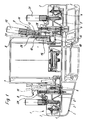
- the terminal block 1 shown in side view in Figure 1 is usually from a large number of lined up, assembled Connection disks 2 formed, seen on Figure 1 in the drawing depth lie side by side.
- Each of the connection plates 2 carries in an electrical insulating plastic housing 3 connections 4 for connection electrical conductor, which in the illustrated embodiment Busbar pieces 5 are connected to plug connections 6.
- An electronic module 7 is also provided, which is connected to the terminal block 1, formed by the connecting plates 2, electrical and is mechanically pluggable.
- the mechanical connection happens in the usual way by inserting appropriately designed housing areas of the housing 8 of the electronics module 7 into a corresponding one Receiving recess in the terminal block 2, which are lined up by the Plastic housing 3 of the connecting plate 2 is formed.
- the plug connection is appropriately mechanically locked.
- this separating device is a separating piece 9, in which both the connector 10 for insertion into the plug connections 6 of the terminal block 1 and thus for electrical Connection between terminal block 1 and electronics module 7, as also test plug connections 11 for inserting a test plug 12 are located.
- the separator 9 is between a closed position and a separation position displaceable on the electronics module 7 captive held.
- the separators are directly in the connector zone of the electronics module 7 provided on this.
- You have a case 13, which engages around the lower edge of the housing 8 of the electronic module 7 and therefore one with the inside of the electronics module housing 8 Section 14 and an outer wall portion 15, which extends in the vertical direction of the electronic module 7.
- the outside lying section 15 includes in its lower end region the connectors 10 with the corresponding plug connections 6 of the connecting disks 2 of the terminal block 1 cooperate. In the upper end region of this section 15 there are upwards open, the test plug connections 11.
- the plug connections are located 6 of the terminal block 1 related to this electronics module 7 outside. This means that this terminal block 1 also if necessary with other electronic modules without a separator can be equipped. These electronic modules would then be so wide that Plug connections or directly the correspondingly designed ends of functional circuit boards inserted directly into the plug connections 6 can be. There is also the option of an electronic module to use, which carries a separator 9 on only one side, while the other side compared to the illustrated embodiment widened accordingly and for direct electrical contacting the plug connections 6 there is set up.
- they include in the separator 9 arranged connector 10 a downward, on the plug connection 6 directional flag 16, located on a track piece 17 is located, from which a contact tab 18 for the Contacting with the pin of the test plug 12 comes off, and from that down another busbar piece 19 goes down to the with respect to the electronics module 7 inner wall portion 14 of the separator 9 runs and here in the interior of the electronics module in the illustrated Embodiment directly contacting the corresponding designed end of a functional circuit board 20 can contact.
- the separator 9 is a sliding contact configuration between the closed position and the disconnected position intended.
- the captive is relocatable Holding the separator 9 on the lower outer wall area of the Housing 8 of the electronics module 7 is achieved in that the wall sections 14 and 15 of the housing 13 of the separator 9 between them define a guide gap 21 into which the lower outer wall area of the housing 8 of the electronics module 7 occurs, so that the separator 9 on the housing 8 can move up and down.
- the wall section concerned of the housing 8 of the electronics module 7 in the height direction from each other recesses 22 and 23 are provided.
- Figures 1 and 2 show the right separator seen on the drawing 9 in its disconnected position.
- the locking hooks 24 and 25 are located in the recesses 22 and 23.
- the electrical connection between the electronics module 7 and the terminal block 2 is separated because the plug-in tabs 16 of the separator 9 upwards from the plug connections 6 are pulled out.
- the separator 9 is essentially a depth extension has according to the terminal block 1 and so many in it electrical connectors 10 are arranged, such as plug connections 6 for the electrical contact between the electrical module 7 and the terminal block 1 are to be made.
- the electronics can now be operated in the raised position by inserting one or more test plugs 12 into the corresponding ones Test connector 11 of the separator 9 are checked.
- This consists essentially of the shown Embodiment molded on the housing 13 of the separator 9 angular springs 26 with their lower legs in a further recess 27 provided for this purpose in the corresponding wall section of the housing 8 of the electronics module 7 enter blocking can.
- the arrangement is such that the spring piece 26 in Rest position on its side facing away from the electronics housing 7 in the test connector 11 protrudes so far that the pin of the test connector 12 automatically when the spring piece 26 is inserted into the Blocking position presses.
- the separators 9 remain regardless of their position on the electronics module.
- the outer-walled section 15 of the housing 13 of the separator 9 expediently as long upwards extends that the upper end also in the closed position of the Partition 9 still clearly visible and manageable above the Wiring level of the connection block 1 is and that too still offers the opportunity to save space and space close to the Separator 9 (see left side of Figure 1) a cross connector comb 28 to provide a potential transverse distribution by contacting of the adjacent conductor rail pieces 5 in the connecting disks 2 of the Terminal block 1 allows.
- the housing 13 of the separator 9 is also useful on the top provided with a bracket or hook piece 29, which the handling the separating piece 9, for example with the aid of a screwdriver, serves.
- the vertical extension of the housing 13 also ensures the good visibility and accessibility of this upper separator end for actuation and, in the upper disconnected position of the separator 9, a comfortable to use, visually well visible and clearly above the wiring level of the terminal block 1 lying plug-in for the test plug 12. The latter applies even if In addition to testing the electronics, a field device test is also useful takes place and in addition to the test plugs 12 for the Electronics test also spatially offset laterally downwards in corresponding plug connections 30 of the connecting disks 2 of the Terminal block 1 test plug 31 can be inserted.
Landscapes
- Connections Arranged To Contact A Plurality Of Conductors (AREA)
- Coupling Device And Connection With Printed Circuit (AREA)
- Details Of Connecting Devices For Male And Female Coupling (AREA)
Description
- Figur 1
- einen Anschlußklemmenblock mit aufgestecktem Elektronikmodul in teilweiser Schnittdarstellung mit einem Trennstück in der Trenn- und Prüfstellung und einem Trennstück in der Schließstellung,
- Figur 2
- eine Teilansicht der Anordnung nach Figur 1 mit Darstellung des Trennstückes in der Trenn- und Prüfstellung sowie der angrenzenden Bereiche des Elektronikmoduls und des Anschlußklemmenblockes in vergrößertem Maßstab.
Claims (11)
- Anschlußklemmenblock (1) mit damit elektrisch und mechanisch steckverbindbarem Elektronikmodul (7) und einer an dem Elektronikmodul (7) angeordneten Trenneinrichtung (9) in der elektrischen Verbindung zwischen dem Anschlußklemmenblock (1) und dem Elektronikmodul (7), dadurch gekennzeichnet, daß die Trenneinrichtung ein die elektrischen Steckverbinder (10) des Elektronikmodules (7) zur elektrischen Verbindung zum Anschlußklemmenblock (1) und Prüf-steckeranschlüsse (11) beinhaltendes Trennstück (9) ist, das in der Steckverbindungszone des Elektronikmodules (7) an diesem zwischen einer Schließ- und einer Trennstellung verlagerbar gehalten ist.
- Anschlußklemmenblock nach Anspruch 1, gekennzeichnet durch eine zwischen dem Trennstück (9) und dem Gehäuse (8) des Elektronikmodules (7) wirkende Blockiervorrichtung (26, 27), die in der Trennstellung des Trennstückes (9) durch Einstecken eines Prüfsteckers (12) betätigbar ist.
- Anschlußklemmenblock nach einem der vorhergehenden Ansprüche, dadurch gekennzeichnet, daß das Gehäuse (13) des Trennstückes (9) einen sich an der Außenwand des Gehäuses (8) des Elektronikmodules (7) in dessen Höhenrichtung erstreckenden Abschnitt (15) aufweist, in dessen unterem Bereich sich die elektrischen Steckverbinder (10) befinden, für die an entsprechender, gegenüberliegender Stelle im Anschlußklemmenblock (1) Steckanschlüsse (6) vorgesehen sind.
- Anschlußklemmenblock nach Anspruch 3, dadurch gekennzeichnet, daß an dem Abschnitt (15) des Gehäuses (13) des Trennstückes (9) in dessem oberen Endbereich die Prüfsteckeranschlüsse (11) vorgesehen sind.
- Anschlußklemmenblock nach einem der vorhergehenden Ansprüche, dadurch gekennzeichnet, daß das Gehäuse (13) des Trennstückes (9), die Unterkante einer Außenwand des Gehäuses (8) des Elektronikmodules (7) übergreifend einen bezüglich des Elektronikmodulgehäuses (8) innen liegenden Abschnitt (14) sowie einen außen liegenden Abschnitt (15) aufweist, die zwischen sich einen Führungsspalt (21) für diesen Wandbereich des Gehäuses (8) des Elektronikmodules (7) bilden.
- Anschlußklemmenblock nach Anspruch 5, dadurch gekennzeichnet, daß in dem mit dem Trennstück (9) zusammenwirkenden Wandungsbereich des Gehäuses (8) des Elektronikmodules (7) in Höhenerstreckung abständig übereinander Rastausnehmungen (22, 23) vorgesehen sind, für die zwecks Halterung des Trennstückes (9) am Elektronikmodul (7) sowie zwecks Sicherung der Schließ- und Trennstellung des Trennstückes (9) am Gehäuse (13) Rasthaken (24, 25) in entsprechendem Abstand voneinander vorgesehen sind.
- Anschlußklemmenblock nach Anspruch 2, dadurch gekennzeichnet, daß die Blockiervorrichtung aus am Trennstück (9) vorgesehenen Federstücken (26) gebildet ist, die in ihrer Ruhestellung in Prüfsteckeranschlüsse (11) des Trennstückes (9) vorstehen und die in Richtung der Wandung des Gehäuses (8) des Elektronikmodules (7) federnd verlagerbar sind, wobei in der Wand in entsprechender Lage sie blockierend aufnehmende Ausnehmungen (27) vorgesehen ist.
- Anschlußklemmenblock nach einem der vorhergehenden Ansprüche, dadurch gekennzeichnet, daß die Steckverbinder (10) in den Trennstücken (9) nach unten auf die Steckanschlüsse (6) des Anschlußklemmenblockes (1) weisende Steckfahnen (16) haben, die an Stromschienenstücken (17) sitzen, von denen nach oben eine Kontaktfahne (18) für den Prüfsteckeranschluß abzweigt und von denen nach unten ein weiteres Stromschienenstück (19) abzweigt, das bis in den bezüglich des Elektronikmodulgehäuses (8) innenwandig liegenden Abschnitt (14) des Trennstückes (9) verläuft und hier als Kontakt zur Elektronik des Elektronikmoduls (7) ausgebildet ist.
- Anschlußklemmenblock nach Anspruch 1, dadurch gekennzeichnet, daß der aus einzelnen Anschlußscheiben (2) zusammengesetzte Anschlußklemmenblock (1) in den Anschlußscheiben (2) räumlich benachbart zu dem Trennstück (9) Steckaufnahmen für einen Querverbinderkamm (28) aufweist.
- Anschlußklemmenblock nach Anspruch 9, dadurch gekennzeichnet, daß der bezüglich des Elektronikmodules (7) außenwandig liegende Abschnitt (15) des Gehäuses (13) des Trennstückes (9) in Höhenerstreckung so hoch geführt ist, daß benachbart zu ihm auch in seiner Schließstellung ein Freiraum für den Querverbinderkamm (28) verbleibt.
- Anschlußklemmenblock nach einem der vorhergehenden Ansprüche, gekennzeichnet durch eine Höhenverlagerbarkeit des Trennstückes (9) und Hochlage der Prüfsteckeranschlüsse (11) derart, daß in der Trennstellung des Trennstückes (9) eingesteckte Prüfstecker höhenversetzt oberhalb zu Prüfsteckern (31) liegen, die in seitlich außen benachbarten Prüfanschlüssen (30) des Anschlußklemmenblockes (1) eingesteckt sind.
Applications Claiming Priority (2)
| Application Number | Priority Date | Filing Date | Title |
|---|---|---|---|
| DE4438800A DE4438800C1 (de) | 1994-10-31 | 1994-10-31 | Anschlußklemmenblock mit Elektronikmodul |
| DE4438800 | 1994-10-31 |
Publications (3)
| Publication Number | Publication Date |
|---|---|
| EP0709917A2 EP0709917A2 (de) | 1996-05-01 |
| EP0709917A3 EP0709917A3 (de) | 1998-03-04 |
| EP0709917B1 true EP0709917B1 (de) | 1999-03-24 |
Family
ID=6532088
Family Applications (1)
| Application Number | Title | Priority Date | Filing Date |
|---|---|---|---|
| EP95113807A Expired - Lifetime EP0709917B1 (de) | 1994-10-31 | 1995-09-02 | Anschlussklemmenblock mit Elektronikmodul |
Country Status (6)
| Country | Link |
|---|---|
| US (1) | US5588881A (de) |
| EP (1) | EP0709917B1 (de) |
| JP (1) | JP3853408B2 (de) |
| AT (1) | ATE178164T1 (de) |
| DE (2) | DE4438800C1 (de) |
| ES (1) | ES2129165T3 (de) |
Families Citing this family (36)
| Publication number | Priority date | Publication date | Assignee | Title |
|---|---|---|---|---|
| DE4440102C1 (de) * | 1994-11-10 | 1996-05-15 | Weidmueller Interface | Modulare Steuerungsanlage mit integriertem Feldbusanschluß |
| FR2732518B1 (fr) * | 1995-03-29 | 1997-04-30 | Entrelec Sa | Agencement de connexion pour fils conducteurs electriques et module, notamment de type bloc de jonction, equipe d'un tel agencement |
| US5890934A (en) * | 1997-09-30 | 1999-04-06 | Weidmuller Inc. | Pluggable connector assembly for printed circuit boards |
| DE29720704U1 (de) | 1997-11-21 | 1998-01-15 | WECO Wester, Ebbinghaus GmbH & Co. KG, 63452 Hanau | Elektrische Anschlußklemme |
| FR2773914B1 (fr) * | 1998-01-21 | 2000-04-21 | Entrelec Sa | Bloc de raccordement electrique a piece d'interconnexion accessible par une prise de test et piece d'interconnexion pour un tel bloc |
| DE29804284U1 (de) * | 1998-03-11 | 1998-05-07 | Weidmüller Interface GmbH & Co, 32760 Detmold | Steuerungsanlage für elektronische Steuerungs- und Automatisierungssysteme |
| DE29806691U1 (de) | 1998-04-15 | 1998-05-28 | Weidmüller Interface GmbH & Co, 32760 Detmold | Montagefuß für anreihbare Einbaugehäuse oder Klemmen |
| FR2777702B1 (fr) * | 1998-04-17 | 2000-06-16 | Entrelec Sa | Dispositif de connexion auto-denudant |
| US6220901B1 (en) * | 1998-04-30 | 2001-04-24 | General Electric Company | Electric motor terminal board assembly |
| US6074241A (en) * | 1998-06-05 | 2000-06-13 | The Whitaker Corporation | Non-slip spring clamp contact |
| DE29901194U1 (de) | 1999-01-25 | 1999-05-20 | Weidmüller Interface GmbH & Co., 32760 Detmold | Busleiterabschnitt für ein elektrisches Gerät |
| DE19964156B4 (de) * | 1999-01-25 | 2004-07-15 | Weidmüller Interface Gmbh & Co. | Elektrisches Gerät |
| DE29901348U1 (de) | 1999-01-27 | 1999-04-29 | Abb Patent Gmbh, 68309 Mannheim | Elektrisches Installationsgerät |
| DE29910179U1 (de) * | 1999-06-11 | 2000-11-02 | Weidmüller Interface GmbH & Co, 32760 Detmold | Steckverbinder für elektrische Steuerungen |
| DE29916303U1 (de) | 1999-09-16 | 2001-02-22 | Weidmüller Interface GmbH & Co, 32760 Detmold | Modul mit Koppelelementen |
| DE10011385A1 (de) * | 2000-03-09 | 2001-09-13 | Abb Cmc Carl Maier Ag Schaffha | Einbaugerät für elektrische Niederspannungsinstallation |
| DE10045498C5 (de) * | 2000-09-13 | 2006-06-08 | Phoenix Contact Gmbh & Co. Kg | Elektrische Reihenklemme |
| DE20106710U1 (de) * | 2001-04-18 | 2001-08-09 | Phoenix Contact Gmbh & Co., 32825 Blomberg | Elektrische Klemme |
| DE20211002U1 (de) | 2002-07-19 | 2003-12-04 | Weidmüller Interface Gmbh & Co. | Modul für ein elektrisches Gerät, insbesondere Feldbusmodul |
| DE102004043466B4 (de) * | 2004-09-08 | 2007-08-02 | Siemens Ag | Strom-Einspeisemodul mit Käfig-Zugfederklemmen |
| DE102005017712A1 (de) * | 2005-04-15 | 2006-12-14 | Abb Patent Gmbh | Automatisierungssystem |
| DE102006030953A1 (de) * | 2005-08-17 | 2007-03-15 | Abb Patent Gmbh | Elektrische Einrichtung, insbesondere Leitungs- Fehlerstrom- oder Motorschutzschalter |
| DE102005040657A1 (de) * | 2005-08-26 | 2007-03-15 | Phoenix Contact Gmbh & Co. Kg | Elektrische Anschlussklemme |
| DE102005043878A1 (de) * | 2005-09-14 | 2007-03-22 | Wöhner GmbH & Co. KG Elektrotechnische Systeme | Stromschienenanschlussmodul |
| DE102006053352B3 (de) * | 2006-11-10 | 2008-04-17 | Phoenix Contact Gmbh & Co. Kg | Anschlußverteiler |
| DE202007005373U1 (de) * | 2007-04-12 | 2008-08-21 | Weidmüller Interface GmbH & Co. KG | Reihenklemmensystem |
| DE102007059640B4 (de) * | 2007-12-10 | 2009-11-26 | Wago Verwaltungsgesellschaft Mbh | Anschlussmodul |
| WO2011120881A1 (de) * | 2010-03-31 | 2011-10-06 | Weidmüller Interface GmbH & Co. KG | Busfähiges anschlussmodul |
| DE102011087209B4 (de) * | 2011-11-28 | 2019-02-28 | Siemens Aktiengesellschaft | Elektroinstallationsgerät |
| TW201507300A (zh) * | 2013-08-07 | 2015-02-16 | Switchlab Inc | 導線端子座改良結構 |
| US9825459B2 (en) | 2014-02-13 | 2017-11-21 | Erico International Corporation | Disconnect splice block and modular surge device |
| DE102014105316A1 (de) | 2014-04-14 | 2015-10-15 | Weidmüller Interface GmbH & Co. KG | Reihenklemmenblock |
| FR3026238B1 (fr) * | 2014-09-23 | 2016-10-21 | Abb France | Partie de barre conductrice pour un appareil electrique |
| DE202017106533U1 (de) * | 2017-10-27 | 2019-01-30 | Wago Verwaltungsgesellschaft Mbh | Elektrische Reihenklemme |
| DE102018109861A1 (de) * | 2018-04-24 | 2019-10-24 | Phoenix Contact Gmbh & Co. Kg | Steckverbindungsanordnung für eine Reihenklemme |
| DE102020001046A1 (de) | 2020-02-18 | 2021-08-19 | Hottinger Baldwin Messtechnik Gesesllschaft mit beschränkter Haftung | Hutschienen-Befestigungsmodul für räumlich begrenzte Schaltschränke |
Family Cites Families (7)
| Publication number | Priority date | Publication date | Assignee | Title |
|---|---|---|---|---|
| DE1238087B (de) * | 1965-03-25 | 1967-04-06 | Siemens Ag | Reihenleitungsverbinder mit Trennstelle |
| SE377636B (de) * | 1973-11-12 | 1975-07-14 | Asea Ab | |
| DE3233255C2 (de) * | 1982-09-08 | 1984-09-27 | Phönix Elektrizitätsgesellschaft H. Knümann GmbH & Co KG, 4933 Blomberg | Elektrische Anschlußklemme, insbesondere Schaltanlagen-Reihenklemme |
| DE3311820C2 (de) * | 1983-03-31 | 1988-10-20 | C.A. Weidmüller GmbH & Co, 4930 Detmold | Reihenklemme mit ein elektrisches Wirkelement tragendem Schwenkhebel |
| FR2659118B1 (fr) * | 1990-03-02 | 1992-05-07 | Entrelec Sa | Dispositif de fixation d'un bloc de jonction sur un profile support symetrique. |
| DE4121836C2 (de) * | 1991-07-02 | 1994-07-07 | Weidmueller C A Gmbh Co | Reihenklemme mit Aufsteckmodul |
| US5407367A (en) * | 1993-09-27 | 1995-04-18 | Vernitron Corporation | Barrier terminal strip assembly |
-
1994
- 1994-10-31 DE DE4438800A patent/DE4438800C1/de not_active Expired - Fee Related
-
1995
- 1995-09-02 AT AT95113807T patent/ATE178164T1/de not_active IP Right Cessation
- 1995-09-02 EP EP95113807A patent/EP0709917B1/de not_active Expired - Lifetime
- 1995-09-02 DE DE59505430T patent/DE59505430D1/de not_active Expired - Lifetime
- 1995-09-02 ES ES95113807T patent/ES2129165T3/es not_active Expired - Lifetime
- 1995-10-18 US US08/544,482 patent/US5588881A/en not_active Expired - Fee Related
- 1995-10-31 JP JP28327395A patent/JP3853408B2/ja not_active Expired - Fee Related
Also Published As
| Publication number | Publication date |
|---|---|
| JPH08227760A (ja) | 1996-09-03 |
| EP0709917A2 (de) | 1996-05-01 |
| DE4438800C1 (de) | 1996-01-18 |
| ATE178164T1 (de) | 1999-04-15 |
| JP3853408B2 (ja) | 2006-12-06 |
| ES2129165T3 (es) | 1999-06-01 |
| US5588881A (en) | 1996-12-31 |
| EP0709917A3 (de) | 1998-03-04 |
| DE59505430D1 (de) | 1999-04-29 |
Similar Documents
| Publication | Publication Date | Title |
|---|---|---|
| EP0709917B1 (de) | Anschlussklemmenblock mit Elektronikmodul | |
| EP0709920B1 (de) | Modulare Steuerungsanlage | |
| EP0272200B1 (de) | Anschlussleiste für die Fernmeldetechnik | |
| DE19902745B4 (de) | Elektrisches Gerät | |
| EP2862364B1 (de) | Verteileranschlussmodul | |
| EP0900460A1 (de) | Verrastung einer steckverbinderpaarung | |
| EP0914029B1 (de) | Modulares Automatisierungsgerät und Baugruppe eines modularen Automatisierungsgerätes | |
| DE4121836A1 (de) | Reihenklemme mit aufsteckmodul | |
| EP0753916A2 (de) | Sammelschienen-Adaptersystem | |
| EP1113525B1 (de) | Reihenklemme, insbesondere Wandlerklemme, mit einer Querbrückungsvorrichtung | |
| WO2016107713A1 (de) | Überspannungsschutzanordnung für die informations- und telekommunikationstechnik | |
| DE19547557A1 (de) | Elektrische Klemmen mit steckbaren Querbrückern | |
| DE10230292B3 (de) | Träger für Modulgehäuse | |
| EP0477664A1 (de) | Schutzstecker für eine in Telekommunikations-, insbesondere Fernsprechnebenstellenanlagen eingesetzte Verteilerleiste | |
| DE102013111571A1 (de) | Gerätegehäuse, Elektronikgeräte und Steckkontaktträger | |
| DE102005033998A1 (de) | Schneidklemm-Steckverbinder und Einrichtung für die Telekommunikations- und Datentechnik | |
| EP0262325A2 (de) | Anordnung für Hauptverteiler | |
| EP0951105B1 (de) | Mehrfachsteckdose | |
| EP1787358B1 (de) | Strom-einspeisemodul mit käfig-zugfederklemmen | |
| EP0080646A2 (de) | Fassung für ein Miniaturrelais | |
| DE1614401A1 (de) | Elektrische Steckfassung | |
| EP0951104B1 (de) | Steckdose, insbesondere Einbaudose für Elektroinstallationssysteme | |
| DE10338787A1 (de) | Querverbinder für Reihenklemmen | |
| DE10117758A1 (de) | Baugruppe für ein Automatisierungsgerät | |
| DE7920512U1 (de) | Anordnung zum Anschließen elektrischer Leiter |
Legal Events
| Date | Code | Title | Description |
|---|---|---|---|
| PUAI | Public reference made under article 153(3) epc to a published international application that has entered the european phase |
Free format text: ORIGINAL CODE: 0009012 |
|
| AK | Designated contracting states |
Kind code of ref document: A2 Designated state(s): AT CH DE ES FR GB IT LI |
|
| PUAL | Search report despatched |
Free format text: ORIGINAL CODE: 0009013 |
|
| AK | Designated contracting states |
Kind code of ref document: A3 Designated state(s): AT CH DE ES FR GB IT LI |
|
| 17P | Request for examination filed |
Effective date: 19980210 |
|
| GRAG | Despatch of communication of intention to grant |
Free format text: ORIGINAL CODE: EPIDOS AGRA |
|
| 17Q | First examination report despatched |
Effective date: 19980911 |
|
| GRAG | Despatch of communication of intention to grant |
Free format text: ORIGINAL CODE: EPIDOS AGRA |
|
| GRAH | Despatch of communication of intention to grant a patent |
Free format text: ORIGINAL CODE: EPIDOS IGRA |
|
| ITF | It: translation for a ep patent filed | ||
| GRAH | Despatch of communication of intention to grant a patent |
Free format text: ORIGINAL CODE: EPIDOS IGRA |
|
| GRAA | (expected) grant |
Free format text: ORIGINAL CODE: 0009210 |
|
| AK | Designated contracting states |
Kind code of ref document: B1 Designated state(s): AT CH DE ES FR GB IT LI |
|
| REF | Corresponds to: |
Ref document number: 178164 Country of ref document: AT Date of ref document: 19990415 Kind code of ref document: T |
|
| REG | Reference to a national code |
Ref country code: CH Ref legal event code: NV Representative=s name: ISLER & PEDRAZZINI AG Ref country code: CH Ref legal event code: EP |
|
| REF | Corresponds to: |
Ref document number: 59505430 Country of ref document: DE Date of ref document: 19990429 |
|
| REG | Reference to a national code |
Ref country code: ES Ref legal event code: FG2A Ref document number: 2129165 Country of ref document: ES Kind code of ref document: T3 |
|
| GBT | Gb: translation of ep patent filed (gb section 77(6)(a)/1977) |
Effective date: 19990602 |
|
| ET | Fr: translation filed | ||
| PLBE | No opposition filed within time limit |
Free format text: ORIGINAL CODE: 0009261 |
|
| STAA | Information on the status of an ep patent application or granted ep patent |
Free format text: STATUS: NO OPPOSITION FILED WITHIN TIME LIMIT |
|
| 26N | No opposition filed | ||
| REG | Reference to a national code |
Ref country code: GB Ref legal event code: IF02 |
|
| REG | Reference to a national code |
Ref country code: CH Ref legal event code: PCAR Free format text: ISLER & PEDRAZZINI AG;POSTFACH 1772;8027 ZUERICH (CH) |
|
| PGFP | Annual fee paid to national office [announced via postgrant information from national office to epo] |
Ref country code: AT Payment date: 20080915 Year of fee payment: 14 |
|
| PGFP | Annual fee paid to national office [announced via postgrant information from national office to epo] |
Ref country code: GB Payment date: 20080918 Year of fee payment: 14 |
|
| GBPC | Gb: european patent ceased through non-payment of renewal fee |
Effective date: 20090902 |
|
| PG25 | Lapsed in a contracting state [announced via postgrant information from national office to epo] |
Ref country code: AT Free format text: LAPSE BECAUSE OF NON-PAYMENT OF DUE FEES Effective date: 20090902 |
|
| PGFP | Annual fee paid to national office [announced via postgrant information from national office to epo] |
Ref country code: ES Payment date: 20100924 Year of fee payment: 16 Ref country code: CH Payment date: 20100923 Year of fee payment: 16 |
|
| PG25 | Lapsed in a contracting state [announced via postgrant information from national office to epo] |
Ref country code: GB Free format text: LAPSE BECAUSE OF NON-PAYMENT OF DUE FEES Effective date: 20090902 |
|
| PGFP | Annual fee paid to national office [announced via postgrant information from national office to epo] |
Ref country code: IT Payment date: 20100922 Year of fee payment: 16 Ref country code: FR Payment date: 20101005 Year of fee payment: 16 |
|
| PGFP | Annual fee paid to national office [announced via postgrant information from national office to epo] |
Ref country code: DE Payment date: 20110923 Year of fee payment: 17 |
|
| REG | Reference to a national code |
Ref country code: CH Ref legal event code: PL |
|
| PG25 | Lapsed in a contracting state [announced via postgrant information from national office to epo] |
Ref country code: IT Free format text: LAPSE BECAUSE OF NON-PAYMENT OF DUE FEES Effective date: 20110902 |
|
| REG | Reference to a national code |
Ref country code: FR Ref legal event code: ST Effective date: 20120531 |
|
| PG25 | Lapsed in a contracting state [announced via postgrant information from national office to epo] |
Ref country code: LI Free format text: LAPSE BECAUSE OF NON-PAYMENT OF DUE FEES Effective date: 20110930 Ref country code: CH Free format text: LAPSE BECAUSE OF NON-PAYMENT OF DUE FEES Effective date: 20110930 |
|
| PG25 | Lapsed in a contracting state [announced via postgrant information from national office to epo] |
Ref country code: FR Free format text: LAPSE BECAUSE OF NON-PAYMENT OF DUE FEES Effective date: 20110930 |
|
| REG | Reference to a national code |
Ref country code: ES Ref legal event code: FD2A Effective date: 20130704 |
|
| PG25 | Lapsed in a contracting state [announced via postgrant information from national office to epo] |
Ref country code: ES Free format text: LAPSE BECAUSE OF NON-PAYMENT OF DUE FEES Effective date: 20110903 Ref country code: DE Free format text: LAPSE BECAUSE OF NON-PAYMENT OF DUE FEES Effective date: 20130403 |
|
| REG | Reference to a national code |
Ref country code: DE Ref legal event code: R119 Ref document number: 59505430 Country of ref document: DE Effective date: 20130403 |