EP2862364B1 - Verteileranschlussmodul - Google Patents
Verteileranschlussmodul Download PDFInfo
- Publication number
- EP2862364B1 EP2862364B1 EP13710363.6A EP13710363A EP2862364B1 EP 2862364 B1 EP2862364 B1 EP 2862364B1 EP 13710363 A EP13710363 A EP 13710363A EP 2862364 B1 EP2862364 B1 EP 2862364B1
- Authority
- EP
- European Patent Office
- Prior art keywords
- contacts
- module
- contact
- base module
- modules
- Prior art date
- Legal status (The legal status is an assumption and is not a legal conclusion. Google has not performed a legal analysis and makes no representation as to the accuracy of the status listed.)
- Active
Links
Images


Classifications
-
- H—ELECTRICITY
- H04—ELECTRIC COMMUNICATION TECHNIQUE
- H04Q—SELECTING
- H04Q1/00—Details of selecting apparatus or arrangements
- H04Q1/02—Constructional details
- H04Q1/14—Distribution frames
-
- H—ELECTRICITY
- H04—ELECTRIC COMMUNICATION TECHNIQUE
- H04Q—SELECTING
- H04Q1/00—Details of selecting apparatus or arrangements
- H04Q1/02—Constructional details
- H04Q1/14—Distribution frames
- H04Q1/142—Terminal blocks for distribution frames
Definitions
- the invention relates to a distribution terminal module for telecommunications and data technology.
- a distributor connection module comprising a housing in which externally accessible input and output contacts for connecting lines or wires are arranged, wherein the housing is formed with a cavity in which functional elements between the input and output contacts are arranged.
- the functional elements are arranged on at least one printed circuit board, which is supported in the housing.
- the input and output contacts are formed, for example, as wire connection contacts in the form of insulation displacement contacts, wherein the input and output contacts are preferably arranged on opposite end sides of the housing. It is also proposed that between each of an input and output contact a separating contact is arranged, which is accessible from the outside.
- a wire connection module comprising a two-part housing and a number of contact elements, wherein the contact elements have at least one connection side, which is designed as a contact for connecting wires.
- the contact element further has an interface over which overvoltage protection elements can be connected.
- the first housing part is formed with recordings, in which two-pole surge arresters are used.
- the contact element has an interface formed as an interface to the surge arrester, which protrudes into the receptacle and contacts a first pole of the surge arrester, the other pole of the surge arrester being contacted by a ground element.
- the invention is based on the technical problem of providing a distributor connection module which enables an improved exchange of functional elements.
- the distribution terminal module for telecommunication and data technology comprises a housing, wherein in the housing electrical input and output contacts are arranged, which are designed as wire connection contacts, wherein in each case an input contact with an output contact is electrically connected, wherein in the housing Functional elements are arranged, which are electrically connected to the output contacts, wherein the input contacts and output contacts via interface contacts are electrically and mechanically connected, wherein the input contacts are arranged in a base module and the output contacts are divided or arranged in at least two sub-modules, wherein the sub-modules from each other independent of the base module are detachable or connectable.
- the functional elements are connected directly to the output contacts or the output contacts having contact elements.
- the wire connection contacts can be contacts for connecting individual wires, such as insulation displacement contacts or wire-wrap contacts, or plug connectors, such as RJ45 sockets.
- the input contacts and the output contacts are formed as insulation displacement contacts.
- the input contacts as a connector and the output contacts are designed as insulation displacement contacts or vice versa.
- the input and output contacts are for connecting dual wires.
- the size of the sub-modules ie the number of output contacts, can vary depending on the application. It is thus possible to assign a submodule to two output contacts in each case. In this case, the sub-modules represent 1-D plugs. This allows minimal reaction to the other remaining input and output contacts. There are, however Use cases conceivable, for example, where three, four or more output contacts are assigned to a submodule.
- the input and output contacts are preferably arranged on opposite end sides of the distributor connection module.
- the base module comprises a central part, wherein the input contacts or the contact elements comprising the input contacts are arranged in at least one submodule, which are latched in the middle part.
- the input contacts can be arranged, for example, in exactly one submodule.
- the pitch of the sub-modules for the input and output contacts can also be the same, but need not be the same.
- the connection forces between the one or more submodules with the input contacts are many times greater than the connection forces between the submodules with the output contacts and the base module.
- sub-modules with the input contacts must absorb large tensile forces and replacement is not desired.
- embodiments are possible where the sub-modules are as easily replaceable with the input contacts as the sub-modules with output contacts. This is particularly advantageous if it is to be ranked by switching partial modules.
- POTS plain old telephone service
- MSAN multi-service access node
- the functional elements are designed as surge arresters, preferably as three-pole Surge arresters.
- contact legs of the surge arrester are contacted in fork contacts, which are arranged between the output contacts and the interface contacts.
- the sub-modules are latched to the output contacts in the base module, wherein the base module has latching receptacles for two detent positions of the sub-modules.
- a first detent position be such that the interface contacts of the sub-modules with the output contacts are not yet electrically connected to the interface contacts of the input contacts, which are then electrically connected in the second detent position.
- the functional element is a surge arrester
- the first detent position is preferably dimensioned such that a center electrode of the surge arrester is already electrically connected to a ground rail, whereas the interface contacts do not yet.
- the sub-modules are combined with the output contacts by means of at least one fastening means to form a structural unit.
- all sub-modules are summarized to form a structural unit.
- the fasteners connect the sub-modules so reversible that after assembly, the fastener can be solved again to remove a single sub-module.
- the fastening means may be a separate component (for example a frame) or else the sub-modules themselves are each formed with fastening means in order to be fastened to one another.
- each sub-module has a groove on one side wall and a spring on the other side wall to form a tongue-and-groove connection with an adjacent sub-module.
- Other soluble compounds such as male or female connections, are also possible.
- the separate fastening means can also be designed such that this can be removed after plugging the unit.
- the sub-modules with the input contacts may also have such fastening means.
- At least one locking element is arranged on the base module, by means of which the submodules of the output contacts and / or the structural unit are locked in the base module. This prevents accidental removal of a sub-module and / or the assembly. For the targeted removal of a sub-module then first the locking element must be solved and then the attachment between the sub-modules (if this is still present). Alternatively or additionally, the submodules may be associated with the input contacts such a locking element.
- the interface contacts are designed as contact tongues and double spring contacts.
- the interface contacts of the input contacts are designed as double spring contacts and the interface contacts of the output contacts as contact tongues.
- the interface contacts can also be designed as fork contacts.
- both interface contacts may be formed as fork contacts or an interface contact is as a fork contact and the other interface contact is formed as a contact tongue.
- the output contacts are connected to test contacts via which, for example, it is possible to measure in the line or other functional elements can be connected.
- the base module has slots, the base module accessible from the top slots and of the Has underside accessible slots, the slots accessible from the bottom are longer.
- a base module is higher when the input contacts are connected, and the length of the slots makes it possible to set the height to a complete distributor connection module.
- the base module is at least as high as a complete manifold connection module when affixed over the longer slots.
- a distributor connection module 1 is shown for every eight pairs.
- the distributor connection module 1 comprises a base module 2 and eight sub-modules 3.
- the base module 2 is first of all based on the Fig. 4 and 7 explained in more detail.
- the base module 2 comprises a housing 4 with sixteen chambers 5 for contact elements 6.
- Each contact element 6 comprises an input contact 7 of the distribution terminal module 1 in the form of insulation displacement contact and an interface contact 8 in the form of a symmetrical double spring contact.
- a U-shaped element 9 from the bottom of the insulation displacement contact a U-shaped element 9, from whose legs 10 vertically upwards each extending a spring 11.
- the two springs 11 touch each other in a contact region 12.
- the contact elements 6 are then inserted into the chambers 5, so that the insulation displacement contacts are in contact slots 13.
- the housing 4 has four openings 14, which are each associated with two input contact pairs. These openings 14 serve as a cable guide and strain relief.
- the base module 2 comprises a ground rail 15 with eight contact lugs 16 and two fork contacts 17 (see Fig. 7 ), where in Fig. 7 only one fork contact 17 can be seen.
- the base module 2 comprises two support elements 18, which on their outer sides fastening means 19 for receiving a Steckzifferhalters 20 (see Fig. 3 ) exhibit. In the Steckzifferhalter 20 then a plug-in number 51 can be inserted (see Fig. 1 ).
- the base module 2 is formed with further cable guides. It should be noted that the base module 2 may be formed as a one-piece housing or multi-part, which is due to the locking lugs in Fig. 4 can be recognized and based on Fig. 11 will be explained later in more detail.
- the sub-module 3 comprises a housing 21, an insert 22, two contact elements 23 and a three-pole surge arrester 50.
- Each contact element 23 comprises an output contact 24 of the distribution terminal module 1 in the form of an insulation displacement contact and a test contact 25 which are connected to each other via a web 26 are electrically connected.
- the test contacts 25 are formed as contact tongues.
- a connecting web 27 extends, at the end facing away from the web 26 an interface contact 28 is arranged in the form of a contact tongue.
- the connecting webs 27 each have a bend 29, of which in each case a connection contact 30 in the form of a fork contact goes off. How out Fig.
- the terminal contacts 30 of two contact elements 23 for a double wire at a certain distance against each other so that they can each contact a contact pin 31 of an outer electrode 32 of the surge arrester 50.
- a center electrode 33 of the surge arrester 50 is connected to a fail-safe contact 34, which short-circuits the outer electrodes 32 in the event of overvoltage and connects to ground via the center electrode.
- the two contact elements 23 form a contact pair for a double wire and are then inserted into the insert 22 from below, wherein the surge arrester 50 is connected with its contact pins 31 to the connection contacts 30. Subsequently, the insert 22 is pushed into the housing 21, where this locked.
- the fail-safe contact 34 is accessible through an incision 36 of the housing 21 and is contacted by a contact tab 16 of the ground rail 15. It should be noted that in embodiments without fail-safe contact 34, the contact tab 16 directly contacts the center electrode 33. Furthermore, the dome 37 next to the contact slots 35 openings 38 through which the test contacts 25 are accessible from the outside (see Fig. 1 ).
- the housing 21 On the one side wall 39, the housing 21 has two cross-sectionally L-shaped extensions 40 which form a groove 41. Accordingly, the other side wall 42 has a cross-sectionally T-shaped extension 43, which forms a spring 41 which fits into the groove 41.
- a plurality of sub-modules 3 can be connected to form a structural unit, so that then the structural unit can be inserted as a part in the base module 2.
- the holding forces of the tongue and groove connection are preferably designed to be larger than the tensile forces occurring when removing wires from the insulation displacement contacts.
- the interface contacts 28 of the sub-modules 3 dive into the interface contacts 8 of the base module 2 and electrically connect the input contacts 7 of the base module 2 with the output contacts 24 of the sub-modules 3 (see Fig. 7 ).
- connection contacts 30 can also be rotated so that the surge arrester 50 is perpendicular to the longitudinal direction LK of the contact elements 23 with its longitudinal direction LA.
- FIG. 8 is shown how three distribution terminal modules 1 are placed on a mounting tray 60, wherein each of the fork contacts 17 of Earth rail 15 contact the mounting trough 60 and so make a ground connection to the surge arrester 50.
- Fig. 9 is shown how the base module 2 is placed on the mounting tray 60. If the contact elements 6 are arranged captively in the base module 2, then the base module 2 can be plugged into the mounting trough 60 in a pre-assembled manner. Otherwise, the base module 2 is first equipped with the sub-modules 3 and then attached to the mounting tray 60 turned plugged (see Fig. 10 ) and connected, wherein in the illustrated embodiment previously the Steckzifferhalter 20 have been removed for reasons of space.
- the base module 2 comprises a central part 70 and four sub-modules 71 for the contact elements 6 and input contacts 7. Each sub-module 71 is designed to receive four contact elements 6, corresponding to two pairs.
- the sub-modules 71 each have a housing 71a, which is preferably in one piece. Other divisions such as 1 DA or 4 DA are possible.
- the middle part 70 has latching receptacles 72 and the sub-modules 71 latching lugs 73.
- the latching connection is preferably dimensioned such that the connection forces are considerably greater than between the sub-modules 3 and the base module 2.
- the contact elements 6 can first be inserted into the sub-modules 71 and then latched to the middle part 70. Alternatively, it is possible to first insert the contact elements 6 into the middle part 70 and then latch the submodules 71. Finally, it is also conceivable to first lock the sub-part 70 and sub-module 71 and then insert the contact elements 6. With regard to the formation of the contact elements 6 can be fully content to the comments Fig. 7 to get expelled.
- the sub-modules 71 have on their outer sides ribs 74, which prevent excessive bending of the base module 2 (please refer Fig. 13 ). Instead of the ribs 74, other elements such as pins are conceivable that limit a bending path.
- the middle part 70 comprises first latching receptacles 75 and second latching receptacles 76 for the partial modules 3 with the output contacts 24, which will be explained in more detail later.
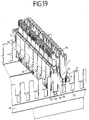
- the base module 2 or middle part 70 has slots 77, 78, wherein the base module 7 or middle part 70 accessible from the top 79 slots 77 and accessible from the bottom 80 slots 78, wherein the accessible from the bottom 80 slots 78 longer are.
- the function of the slots of different lengths 77, 78 will now briefly on the basis of Fig. 19 be explained.
- a mounting trough 60 is shown, on which a complete distribution terminal module 1 and a base module 2 are plugged.
- the mounting trough 60 has tines 61 and latching openings 62, in contrast to the representation in FIG Fig. 10 the distribution terminal module 1 and the base module 2 are not placed on the tines 61, but between two prongs 61 on the mounting trough 60.
- the complete distributor connection module 1 is attached to the underside 80 of the base module 2, ie the tines 61 run in the longer slots 78, so that the complete distributor connection module 1 is deeply immersed. It can be provided that the slot 78 on each side of the distribution terminal module 1 is continuous or two slots per side are available.
- a latching nose 81 of the base module 2 then dips into the latching opening 62, so that the distribution connection module 1 sits firmly on the mounting trough 60.
- the base module 2 shown behind, however, is plugged with the top 79. Since the slots 77 are shorter, this does not dip so deep and the input contacts 7 are at the same height as the output contacts 24 of the complete distribution terminal module 1. This hinder already mounted distribution terminal modules 1 does not impede the connection of wires of a new base module. 2
- FIG. 11 Another difference between the embodiment in Fig. 11 to the in Fig. 4 is that the contact lugs 16 of the ground rail 15 have no bending, but lie in a plane with the rail. This will be explained later.
- Fig. 14 the chambers 5 are shown enlarged, wherein the interface contacts 8 are shown in the form of double-spring contacts with the two springs 11.
- the chambers 5 are laterally provided with openings 90, which also allows the use of printed circuit boards in the sub-modules 3 as interface contacts. Behind the chambers 5, the contact tabs 16 of the ground rail 15 are arranged.
- the housing 21 has in contrast to the embodiment according to Fig. 5 and 6 no incision 36, but a continuous cover 91, so that the surge arrester 50 is arranged in the assembled state of the sub-module 3 safe to touch in the housing 21.
- Another difference of the housing 21 are semi-cylindrical knobs 92, which simplify in particular pulling the sub-modules 3 from the base module 2.
- Another difference of the housing 21 is that no means for connecting sub-modules 3 are provided with each other.
- the housing 21 has guide rails 93 and two latching forks 94.
- the latching forks 94 By means of the latching forks 94, the submodule 3 can be latched into the first latching receptacles 75 or the second latching receptacles 76 of the base module 2.
- the distance of the first and second Ratagen 75, 76 to each other dimensioned such that when the locking forks 94 sit in the first latching receptacle 75, the interface contacts 8 and 28 still have no electrical contact, but preferably a resilient contact tab 95 of a contact element 96 already the contact tab 16 of the ground rail 15 contacted.
- This contact element 96 has a base part 97, from which the locking tab 95 is resiliently cut free.
- a U-shaped portion 98 is arranged, from whose legs 99 in each case a contact 100 goes off, which is bent by 90 ° to the legs 99.
- the U-shaped portion with its legs 99 and the contacts 100 may also be referred to as a fork contact, wherein the actual contacts are bent.
- the insert 22 is modified accordingly to receive this contact element 96. Furthermore, in the insert 22 in the Fig. 5 and 6 account for detecting locking means, which are replaced here by the locking forks 94 on the housing 21. As in the embodiment according to Fig. 5 and 6 First, the contact elements 23 are inserted with the surge arrester 50 in the insert 22.
- the contact element 96 is attached to the surge arrester 50, wherein the two contacts 100, the center electrode 33 of the surge arrester 50 contact, which in Fig. 18 is shown.
- the interface contacts 28 are in front of the contact tabs 16 of the ground rail 15, whereas the contact tab 95 of the contact element 96 is behind the contact tab 16 and contacted.
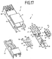
- FIG. 16 Another difference of the housing 21 is in Fig. 16 shown a rear view of the housing of Fig. 17 represents.
- a wall 101 is arranged so that between a rear wall 102 of the dome 37 and the wall 101, a channel 103 is formed.
- openings 104 are provided in the channel 103 .
- the width of the channel 103 and the height of the wall 101 are dimensioned so that there is a standard protection against contact to a cut in the insulation displacement slot vein.
- a hook of a placement tool can be guided through the opening 104 in order to pull the individual submodule 3 out of the base module 2 or to reach a grid position in the first latching receptacle 75.
- the base module 2 with its interface contacts 8 a universally connectable system platform represents in which, depending on the application, suitable sub-modules 3 can be inserted, with the only prerequisite is that the sub-modules 3 have a matching interface contact 28 for the base module 2.
Description
- Die Erfindung betrifft ein Verteileranschlussmodul für die Telekommunikations- und Datentechnik.
- Aus der
DE 100 29 649 A1 ist ein Verteileranschlussmodul bekannt, umfassend ein Gehäuse, in dem von außen zugänglich Eingangs- und Ausgangskontakte zum Anschließen von Leitungen oder Adern angeordnet sind, wobei das Gehäuse mit einem Hohlraum ausgebildet ist, in dem Funktionselemente zwischen den Eingangs- und Ausgangskontakten angeordnet sind. Die Funktionselemente sind dabei auf mindestens einer Leiterplatte angeordnet, die in dem Gehäuse abgestützt ist. Die Eingangs- und Ausgangskontakte sind dabei beispielsweise als Aderanschlusskontakte in Form von Schneid-Klemm-Kontakten ausgebildet, wobei die Eingangs- und Ausgangskontakte vorzugsweise an gegenüberliegenden Stirnseiten des Gehäuses angeordnet sind. Weiter wird vorgeschlagen, dass zwischen einem Eingangs- und Ausgangskontakt jeweils ein Trennkontakt angeordnet ist, der von außen zugänglich ist. - Aus der
DE 10 2007 026 096 A1 ist ein Aderanschlussmodul bekannt, umfassend ein zweiteiliges Gehäuse und eine Anzahl von Kontaktelementen, wobei die Kontaktelemente mindestens eine Anschlussseite aufweisen, die als Kontakt zum Anschließen von Adern ausgebildet ist. Das Kontaktelement weist weiter eine Schnittstelle auf, über die Überspannungs-Schutzelemente anschließbar sind. Das erste Gehäuseteil ist mit Aufnahmen ausgebildet, in die zweipolige Überspannungsableiter eingesetzt sind. Das Kontaktelement weist eine als Schnittstelle zum Überspannungsableiter ausgebildete Kontaktfläche auf, die in die Aufnahme ragt und einen ersten Pol des Überspannungsableiters kontaktiert, wobei der andere Pol des Überspannungsableiters durch ein Masseelement kontaktiert wird. - Der Erfindung liegt das technische Problem zugrunde, ein Verteileranschlussmodul zu schaffen, das einen verbesserten Austausch von Funktionselementen ermöglicht.
- Die Lösung des technischen Problems ergibt sich durch den Gegenstand mit den Merkmalen des Anspruchs 1. Weitere vorteilhafte Ausgestaltungen der Erfindung ergeben sich aus den Unteransprüchen.
- Hierzu umfasst das Verteileranschlussmodul für die Telekommunikations- und Datentechnik ein Gehäuse, wobei in dem Gehäuse elektrische Eingangs- und Ausgangskontakte angeordnet sind, die als Aderanschlusskontakte ausgebildet sind, wobei jeweils ein Eingangskontakt mit einem Ausgangskontakt elektrisch verbunden ist, wobei in dem Gehäuse Funktionselemente angeordnet sind, die elektrisch mit den Ausgangskontakten verbunden sind, wobei die Eingangskontakte und Ausgangskontakte über Schnittstellenkontakte elektrisch und mechanisch verbunden sind, wobei die Eingangskontakte in einem Basismodul angeordnet sind und die Ausgangskontakte in mindestens zwei Teilmodule unterteilt bzw. angeordnet sind, wobei die Teilmodule voneinander unabhängig von dem Basismodul lösbar oder verbindbar sind. Dabei sind die Funktionselemente direkt mit den Ausgangskontakten bzw. die Ausgangskontakte aufweisenden Kontaktelemente verbunden. Hierdurch ist es möglich, ein Teilmodul aus dem Basismodul zu entfernen, das oder die Funktionselemente zu tauschen und das Teilmodul wieder in das Basismodul zu stecken, ohne dass dies Auswirkungen auf die anderen Eingangs- und Ausgangskontakte hat. Alternativ kann auch ein Teilmodul entfernt werden und durch ein anderes Teilmodul ersetzt werden. Ein weiterer Vorteil ist, dass durch das Entfernen des jeweiligen Teilmoduls die zugehörigen Eingangskontakte galvanisch von den Ausgangskontakten getrennt werden, sodass auftretende Überspannungen beim Wechsel der Funktionselemente nicht auf die Eingangskontakte übertragen werden. Die Aderanschlusskontakte können dabei Kontakte zum Anschließen einzelner Adern sein, wie beispielsweise Schneid-Klemm-Kontakte oder Wire-Wrap-Kontakte, oder aber Steckerbinder, wie beispielsweise RJ45-Buchsen. Vorzugsweise sind die Eingangskontakte und die Ausgangskontakte als Schneid-Klemm-Kontakte ausgebildet. Allerdings sind auch Kombinationen der Kontaktarten möglich, beispielsweise dass die Eingangskontakte als Steckverbinder und die Ausgangskontakte als Schneid-Klemm-Kontakte ausgebildet sind oder umgekehrt. Vorzugsweise dienen die Eingangs- und Ausgangskontakte zum Anschließen von Doppeladern. Die Größe der Teilmodule, d.h. die Anzahl der Ausgangskontakte, kann dabei abhängig vom Anwendungsfall variieren. So ist es möglich, jeweils zwei Ausgangskontakten ein Teilmodul zuzuordnen. In diesem Fall stellen die Teilmodule 1DA-Stecker dar. Dies erlaubt eine minimale Rückwirkung auf die anderen verbliebenen Eingangs- und Ausgangskontakte. Es sind jedoch auch Anwendungsfälle denkbar, wobei beispielsweise drei, vier oder mehr Ausgangskontakte einem Teilmodul zugeordnet sind. Die Eingangs- und Ausgangskontakte sind vorzugsweise an gegenüberliegenden Stirnseiten des Verteileranschlussmoduls angeordnet.
- In einer Ausführungsform umfasst das Basismodul ein Mittelteil, wobei die Eingangskontakte bzw. die die Eingangskontakte umfassenden Kontaktelemente in mindestens einem Teilmodul angeordnet sind, die in dem Mittelteil verrastet sind. Dabei können die Eingangskontakte beispielsweise in genau einem Teilmodul angeordnet sein. Alternativ können auch mehrere Teilmodule für die Eingangskontakte vorgesehen sein, die beispielsweise zwei, vier oder acht Eingangskontakte aufweisen. Dabei sei angemerkt, dass die Teilung der Teilmodule für die Eingangs- und Ausgangskontakte auch gleich sein kann, aber nicht gleich sein muss. Vorzugsweise sind die Verbindungskräfte zwischen dem oder den Teilmodulen mit den Eingangskontakten ein Vielfaches größer als die Verbindungskräfte zwischen den Teilmodulen mit den Ausgangskontakten und dem Basismodul. Dies ist immer dann vorteilhaft, wenn die Teilmodule mit den Eingangskontakten große Zugkräfte aufnehmen müssen und ein Austausch nicht gewünscht ist. Es sind jedoch Ausführungsformen möglich, wo die Teilmodule mit den Eingangskontakten genauso einfach austauschbar sind wie die Teilmodule mit Ausgangskontakten. Dies ist insbesondere vorteilhaft, wenn durch Umstecken von Teilmodulen rangiert werden soll. So ist es beispielsweise möglich, einer Teilnehmerleitung, die an einem Teilmodul mit den Ausgangskontakten angeschlossen ist, eine andere Systemseite zuzuordnen. Beispielsweise wird ein Teilmodul mit den Eingangskontakten, wo POTS (plain old telephone service) ursprünglich angeschlossen war, entfernt und ein Teilmodul gesteckt, das mit einem MSAN (multi service access node) verbunden ist.
- In einer weiteren Ausführungsform sind die Funktionselemente als Überspannungsableiter ausgebildet, vorzugsweise als dreipolige Überspannungsableiter. Vorzugsweise werden dabei Kontaktbeine der Überspannungsableiter in Gabelkontakten kontaktiert, die zwischen den Ausgangskontakten und den Schnittstellenkontakten angeordnet sind.
- In einer weiteren Ausführungsform sind die Teilmodule mit den Ausgangskontakten in dem Basismodul verrastet, wobei das Basismodul Rastaufnahmen für zwei Raststellungen der Teilmodule aufweist. Dabei kann eine erste Raststellung derart sein, dass die Schnittstellenkontakte der Teilmodule mit den Ausgangskontakten noch nicht mit den Schnittstellenkontakten der Eingangskontakte elektrisch verbunden sind, wobei diese dann in der zweiten Raststellung elektrisch verbunden sind. Ist das Funktionselement ein Überspannungsableiter, so ist die erste Raststellung vorzugsweise derart dimensioniert, dass eine Mittelelektrode des Überspannungsableiters mit einer Erdschiene bereits elektrisch verbunden ist, die Schnittstellenkontakte hingegen noch nicht.
- In einer Ausführungsform sind die Teilmodule mit den Ausgangskontakten mittels mindestens eines Befestigungsmittels zu einer Baueinheit zusammengefasst. Vorzugsweise sind dabei alle Teilmodule zu einer Baueinheit zusammenfassbar. Dadurch verringert sich der Aufwand bei der Zusammenstellung des Verteileranschlussmoduls, da nur die eine Baueinheit in das Basismodul gesteckt werden muss. Die Befestigungsmittel verbinden die Teilmodule dabei derart reversibel, dass nach dem Zusammenbau das Befestigungsmittel wieder gelöst werden kann, um ein einzelnes Teilmodul zu entnehmen. Dabei kann das Befestigungsmittel ein separates Bauteil sein (beispielsweise ein Rahmen) oder aber die Teilmodule selbst sind jeweils mit Befestigungsmitteln ausgebildet, um aneinander befestigt zu werden. Beispielsweise hat jedes Teilmodul an der einen Seitenwand eine Nut und an der anderen Seitenwand eine Feder, um eine Nut-Feder-Verbindung mit einem benachbarten Teilmodul zu bilden. Andere lösliche Verbindungen, wie beispielsweise Steck- oder Rastverbindungen, sind ebenfalls möglich. Dabei kann das separate Befestigungsmittel auch derart ausgebildet sein, dass dieses nach Stecken der Baueinheit entfernt werden kann. Alternativ oder zusätzlich können auch die Teilmodule mit den Eingangskontakten solche Befestigungsmittel aufweisen.
- In einer weiteren Ausführungsform ist an dem Basismodul mindestens ein Verriegelungselement angeordnet, mittels dessen die Teilmodule der Ausgangskontakte und/oder die Baueinheit im Basismodul verriegelt werden. Dadurch wird ein versehentliches Entfernen eines Teilmoduls und/oder der Baueinheit verhindert. Zum gezielten Entfernen eines Teilmoduls muss dann zunächst das Verriegelungselement gelöst werden und anschließend die Befestigung zwischen den Teilmodulen (soweit diese noch vorhanden ist). Alternativ oder zusätzlich kann auch den Teilmodulen mit den Eingangskontakten ein solches Verriegelungselement zugeordnet sein.
- In einer weiteren Ausführungsform sind die Schnittstellenkontakte als Kontaktzungen und Doppel-Federkontakte ausgebildet. Vorzugsweise sind die Schnittstellenkontakte der Eingangskontakte als Doppel-Federkontakte und die Schnittstellenkontakte der Ausgangskontakte als Kontaktzungen ausgebildet.
- Alternativ können die Schnittstellenkontakte auch als Gabelkontakte ausgebildet sein. Dabei können beide Schnittstellenkontakte als Gabelkontakte ausgebildet sein oder ein Schnittstellenkontakt ist als Gabelkontakt und der andere Schnittstellenkontakt ist als Kontaktzunge ausgebildet.
- In einer weiteren Ausführungsform sind die Ausgangskontakte mit Prüfkontakten verbunden, über die beispielsweise in die Linie gemessen werden kann oder aber weitere Funktionselemente anschließbar sind.
- In einer weiteren Ausführungsform weist das Basismodul Schlitze auf, wobei das Basismodul von der Oberseite zugängliche Schlitze und von der Unterseite zugängliche Schlitze aufweist, wobei die von der Unterseite zugänglichen Schlitze länger sind. Dadurch liegt ein Basismodul beim Beschalten der Eingangskontakte höher, wobei durch die Länge der Schlitze die Höhe zu einem kompletten Verteileranschlussmodul einstellbar ist. Vorzugsweise ist das Basismodul in dieser Position mindestens so hoch wie ein komplettes Verteileranschlussmodul, wenn dieses über die längeren Schlitze befestigt wird.
- Die Erfindung wird nachfolgend anhand eines bevorzugten Ausführungsbeispiels näher erläutert. Die Fig. zeigen:
- Fig. 1
- eine perspektivische Darstellung eines vollständigen Verteileranschlussmoduls,
- Fig. 2
- eine perspektivische Darstellung eines vollständigen Verteileranschlussmoduls mit einem entfernten Teilmodul,
- Fig. 3
- eine perspektivische Darstellung eines Basismoduls mit einem eingesteckten Teilmodul,
- Fig. 4
- eine perspektivische Darstellung eines Basismoduls,
- Fig. 5
- eine perspektivische Darstellung eines Teilmoduls im zusammengesetzten Zustand,
- Fig. 6
- eine Explosionsdarstellung eines Teilmoduls,
- Fig. 7
- eine perspektivische Darstellung einer Erdschiene mit Kontakten eines Teilmoduls und Kontakten des Basismoduls,
- Fig. 8
- eine perspektivische Darstellung einer Montagewanne mit drei aufgesteckten Verteileranschlussmodulen,
- Fig. 9
- eine perspektivische Teildarstellung einer Montagewanne mit aufgestecktem Basismodul,
- Fig. 10
- eine perspektivische Darstellung einer Montagewanne mit aufgestecktem Verteileranschlussmodul zum Anschließen der Eingangskontakte,
- Fig. 11
- eine Explosionsdarstellung eines Basismoduls einer zweiten Ausführungsform,
- Fig. 12
- eine perspektivische Darstellung eines zusammengesetzten Basismoduls ohne Erdschiene,
- Fig. 13
- eine erste Detaildarstellung des Basismoduls,
- Fig. 14
- eine zweite Detaildarstellung des Basismoduls,
- Fig. 15
- eine perspektivische Vorderansicht eines Teilmoduls in einer zweiten Ausführungsform,
- Fig. 16
- eine perspektivische Rückansicht eines Teils des Teilmoduls von
Fig. 15 , - Fig. 17
- eine Explosionsdarstellung des Teilmoduls von
Fig. 15 undFig. 16 , - Fig. 18
- eine perspektivische Darstellung der elektrischen Kontaktierung und
- Fig. 19
- eine perspektivische Darstellung von einem Verteileranschlussmodul und einem Basismodul auf einer Montagewanne.
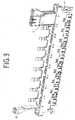
- In der
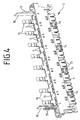
Fig. 1 ist ein Verteileranschlussmodul 1 für jeweils acht Doppeladern dargestellt. Das Verteileranschlussmodul 1 umfasst ein Basismodul 2 sowie acht Teilmodule 3. Bevor das Verteileranschlussmodul 1 näher erläutert wird, wird zunächst das Basismodul 2 anhand derFig. 4 und7 näher erläutert. - Das Basismodul 2 umfasst ein Gehäuse 4 mit sechzehn Kammern 5 für Kontaktelemente 6. Jedes Kontaktelement 6 umfasst einen Eingangskontakt 7 des Verteileranschlussmoduls 1 in Form eines Schneid-Klemm-Kontaktes und einen Schnittstellenkontakt 8 in Form eines symmetrischen Doppel-Federkontaktes. Dabei geht von der Unterseite des Schneid-Klemm-Kontaktes ein U-förmiges Element 9 ab, von dessen Schenkeln 10 senkrecht nach oben sich jeweils eine Feder 11 erstreckt. Die beiden Federn 11 berühren sich dabei in einem Kontaktbereich 12. Die Kontaktelemente 6 werden dann in die Kammern 5 gesteckt, sodass die Schneid-Klemm-Kontakte in Kontaktschlitzen 13 liegen. Das Gehäuse 4 weist vier Öffnungen 14 auf, die jeweils zwei Eingangskontaktpaaren zugeordnet sind. Diese Öffnungen 14 dienen als Kabelführung und Zugentlastung. Dabei werden jeweils zwei Doppeladern von hinten durch die Öffnung 14 nach vorn geführt und eine Doppelader nach links und eine Doppelader nach rechts zu den Eingangskontakten 7 geführt. Durch diese Aderführung werden Zugkräfte umgeleitet, sodass diese nicht mittelbar durch die Eingangskontakte 7 verlaufen. Weiter umfasst das Basismodul 2 eine Erdschiene 15 mit acht Kontaktlaschen 16 sowie zwei Gabelkontakten 17 (siehe
Fig. 7 ), wobei inFig. 7 nur ein Gabelkontakt 17 zu sehen ist. Weiter umfasst das Basismodul 2 zwei Abstützelemente 18, die an ihren Außenseiten Befestigungsmittel 19 zur Aufnahme eines Steckzifferhalters 20 (sieheFig. 3 ) aufweisen. In den Steckzifferhalter 20 kann dann eine Steckziffer 51 gesteckt werden (sieheFig. 1 ). Des Weiteren ist das Basismodul 2 mit weiteren Kabelführungen ausgebildet. Dabei sei angemerkt, dass das Basismodul 2 als einteiliges Gehäuse ausgebildet sein kann oder aber mehrteilig, was an den Rastnasen inFig. 4 zu erkennen ist und anhand vonFig. 11 später noch näher erläutert wird. - Anhand der
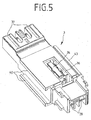
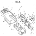
Fig. 5 undFig. 6 soll nun der Aufbau eines Teilmoduls 3 erläutert werden. Das Teilmodul 3 umfasst ein Gehäuse 21, einen Einsatz 22, zwei Kontaktelemente 23 sowie einen dreipoligen Überspannungsableiter 50. Jedes Kontaktelement 23 umfasst einen Ausgangskontakt 24 des Verteileranschlussmoduls 1 in Form eines Schneid-Klemm-Kontaktes sowie einen Prüfkontakt 25, die miteinander über einen Steg 26 elektrisch verbunden sind. Die Prüfkontakte 25 sind dabei als Kontaktzungen ausgebildet. Von dem Steg 26 erstreckt sich ein Verbindungssteg 27, an deren dem Steg 26 abgewandten Ende ein Schnittstellenkontakt 28 in Form einer Kontaktzunge angeordnet ist. Die Verbindungsstege 27 weisen jeweils eine Abwinkelung 29 auf, von denen jeweils ein Anschlusskontakt 30 in Form eines Gabelkontaktes abgeht. Wie ausFig. 6 ersichtlich, liegen sich die Anschlusskontakte 30 von zwei Kontaktelementen 23 für eine Doppelader in einem gewissen Abstand gegenüber, sodass diese jeweils einen Kontaktpin 31 einer Außenelektrode 32 des Überspannungsableiters 50 kontaktieren können. Eine Mittelelektrode 33 des Überspannungsableiters 50 ist mit einem Fail-Safe-Kontakt 34 verbunden, der im Überspannungsfall die Außenelektroden 32 kurzschließt und über die Mittelelektrode mit Masse verbindet. Die beiden Kontaktelemente 23 bilden ein Kontaktpaar für eine Doppelader und werden dann in den Einsatz 22 von unten eingelegt, wobei der Überspannungsableiter 50 mit seinen Kontaktpins 31 an die Anschlusskontakte 30 angeschlossen wird. Anschließend wird der Einsatz 22 in das Gehäuse 21 geschoben, wo dieses verrastet. Die Schneid-Klemm-Kontakte liegen dann in Kontaktschlitzen 35, wobei der Fail-Safe-Kontakt 34 durch einen Einschnitt 36 des Gehäuses 21 zugänglich ist und durch eine Kontaktlasche 16 der Erdschiene 15 kontaktiert wird. Dabei sei angemerkt, dass bei Ausführungsformen ohne Fail-Safe-Kontakt 34 die Kontaktlasche 16 direkt die Mittelelektrode 33 kontaktiert. Des Weiteren weisen die Dome 37 neben den Kontaktschlitzen 35 Öffnungen 38 auf, durch die die Prüfkontakte 25 von außen zugänglich sind (sieheFig. 1 ). An der einen Seitenwand 39 weist das Gehäuse 21 zwei im Querschnitt L-förmige Erstreckungen 40 auf, die eine Nut 41 bilden. Entsprechend weist die andere Seitenwand 42 eine im Querschnitt T-förmige Erstreckung 43 auf, die eine in die Nut 41 passende Feder 44 bildet. Über die Nut 41 bzw. Feder 44 können mehrere Teilmodule 3 zu einer Baueinheit verbunden werden, sodass dann die Baueinheit als ein Teil in das Basismodul 2 gesteckt werden kann. Die Haltekräfte der Nut-Feder-Verbindung sind dabei vorzugsweise größer ausgelegt als die auftretenden Zugkräfte beim Entfernen von Adern aus den Schneid-Klemm-Kontakten. - Beim Zusammenstecken der Baueinheit bzw. Teilmodule 3 mit dem Basismodul 2 tauchen die Schnittstellenkontakte 28 der Teilmodule 3 in die Schnittstellenkontakte 8 des Basismoduls 2 ein und verbinden elektrisch die Eingangskontakte 7 des Basismoduls 2 mit den Ausgangskontakten 24 der Teilmodule 3 (siehe
Fig. 7 ). - Soll nun beispielsweise ein defekter Überspannungsableiter 50 ersetzt werden, so wird nur dessen Teilmodul 3 gezogen (siehe
Fig. 2 ), wobei die anderen sieben Teilmodule 3 mit ihren angeschlossenen Doppeladern gesteckt bleiben, d.h. es wird nur eine Linie unterbrochen. - Weiter sei angemerkt, dass die Anschlusskontakte 30 auch gedreht werden können, sodass der Überspannungsableiter 50 mit seiner Längsrichtung LA senkrecht zur Längsrichtung LK der Kontaktelemente 23 steht.
- In der
Fig. 8 ist dargestellt, wie drei Verteileranschlussmodule 1 auf eine Montagewanne 60 gesteckt sind, wobei jeweils die Gabelkontakte 17 der Erdschiene 15 die Montagewanne 60 kontaktieren und so eine Erdverbindung zu dem Überspannungsableiter 50 herstellen. - In
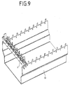
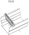
Fig. 9 ist dargestellt, wie das Basismodul 2 auf die Montagewanne 60 gesteckt ist. Sind die Kontaktelemente 6 verliersicher in dem Basismodul 2 angeordnet, so kann das Basismodul 2 bereits vorkonfektioniert beschaltet auf die Montagewanne 60 gesteckt werden. Ansonsten wird das Basismodul 2 zunächst mit den Teilmodulen 3 bestückt und anschließend auf die Montagewanne 60 gedreht aufgesteckt (sieheFig. 10 ) und beschaltet, wobei im dargestellten Ausführungsbeispiel zuvor die Steckzifferhalter 20 aus Platzgründen entfernt wurden. - In den
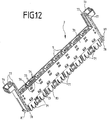
Fig. 11 bis 14 ist ein Basismodul 2 in einer leicht modifizierten Ausführungsform dargestellt. Das Basismodul 2 umfasst ein Mittelteil 70 sowie vier Teilmodule 71 für die Kontaktelemente 6 bzw. Eingangskontakte 7. Jedes Teilmodul 71 ist dabei zur Aufnahme von vier Kontaktelementen 6 ausgebildet, entsprechend zwei Doppeladern. Die Teilmodule 71 weisen dabei jeweils ein Gehäuse 71a auf, das vorzugsweise einstückig ist. Andere Aufteilungen wie beispielsweise 1 DA oder 4 DA sind möglich. Zur Verbindung der Teilmodule 71 mit dem Mittelteil 70 weist das Mittelteil 70 Rastaufnahmen 72 und die Teilmodule 71 Rastnasen 73 auf. Die Rastverbindung ist dabei vorzugsweise derart dimensioniert, dass die Verbindungskräfte erheblich größer als zwischen den Teilmodulen 3 und dem Basismodul 2 sind. Dabei können die Kontaktelemente 6 zunächst in die Teilmodule 71 gesteckt werden und anschließend mit dem Mittelteil 70 verrastet werden. Alternativ ist es möglich, zunächst die Kontaktelemente 6 in das Mittelteil 70 zu stecken und dann die Teilmodule 71 aufzurasten. Schließlich ist auch denkbar, zunächst Mitteilteil 70 und Teilmodul 71 zu verrasten und dann die Kontaktelemente 6 einzustecken. Hinsichtlich der Ausbildung der Kontaktelemente 6 kann vollinhaltlich auf die Ausführungen zuFig. 7 verwiesen werden. Die Teilmodule 71 weisen an ihren Außenseiten Rippen 74 auf, die ein zu starkes Durchbiegen des Basismoduls 2 verhindern (sieheFig. 13 ). Anstelle der Rippen 74 sind auch andere Elemente wie Zapfen denkbar, die einen Biegeweg begrenzen. Weiter umfasst das Mittelteil 70 erste Rastaufnahmen 75 und zweite Rastaufnahmen 76 für die Teilmodule 3 mit den Ausgangskontakten 24, was später noch näher erläutert wird. Schließlich weißt das Basismodul 2 bzw. Mittelteil 70 Schlitze 77, 78 auf, wobei das Basismodul 7 bzw. Mittelteil 70 von der Oberseite 79 zugängliche Schlitze 77 und von der Unterseite 80 zugängliche Schlitze 78 aufweist, wobei die von der Unterseite 80 zugänglichen Schlitze 78 länger sind. Die Funktion der unterschiedlich langen Schlitze 77, 78 soll nun kurz anhand derFig. 19 erläutert werden. - In der
Fig. 19 ist eine Montagewanne 60 dargestellt, auf die ein komplettes Verteileranschlussmodul 1 sowie ein Basismodul 2 aufgesteckt sind. Die Montagewanne 60 weist dabei Zinken 61 und Rastöffnungen 62 auf, wobei im Gegensatz zur Darstellung inFig. 10 das Verteileranschlussmodul 1 sowie das Basismodul 2 nicht auf die Zinken 61, sondern zwischen zwei Zinken 61 auf die Montagewanne 60 gesteckt werden. Dabei wird das komplette Verteileranschlussmodul 1 mit der Unterseite 80 des Basismoduls 2 aufgesteckt, d.h. die Zinken 61 laufen in den längeren Schlitzen 78, sodass das komplette Verteileranschlussmodul 1 tief eintaucht. Dabei kann vorgesehen sein, dass der Schlitz 78 an jeder Seite des Verteileranschlussmoduls 1 durchgängig ist oder aber zwei Schlitze pro Seite vorhanden sind. Eine Rastnase 81 des Basismoduls 2 taucht dann in die Rastöffnung 62 ein, sodass das Verteileranschlussmodul 1 fest auf der Montagewanne 60 sitzt. Das dahinter dargestellte Basismodul 2 ist hingegen mit der Oberseite 79 aufgesteckt. Da die Schlitze 77 kürzer sind, taucht dieses nicht so tief ein und die Eingangskontakte 7 liegen auf gleicher Höhe wie die Ausgangskontakte 24 des kompletten Verteileranschlussmoduls 1. Dadurch behindern bereits montierte Verteileranschlussmodule 1 nicht den Anschaltvorgang von Adern eines neuen Basismoduls 2. - Ein weiterer Unterschied zwischen der Ausführungsform in
Fig. 11 zu der inFig. 4 ist, dass die Kontaktlaschen 16 der Erdschiene 15 keine Biegung aufweisen, sondern in einer Ebene mit der Schiene liegen. Dies wird später noch näher erläutert. InFig. 14 sind die Kammern 5 vergrößert dargestellt, wobei die Schnittstellenkontakte 8 in Form der Doppel-Feder-Kontakte mit den beiden Federn 11 dargestellt sind. Die Kammern 5 sind seitlich mit Öffnungen 90 versehen, was auch den Einsatz von Leiterplatten in den Teilmodulen 3 als Schnittstellenkontakte ermöglicht. Hinter den Kammern 5 sind die Kontaktlaschen 16 der Erdschiene 15 angeordnet. - Anhand der
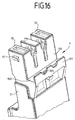
Fig. 15 bis 17 wird nun eine alternative Bauform des Teilmoduls 3 für die Ausgangskontakte 24 näher erläutert, wobei gleiche Elemente wie in der Ausführungsform gemäß denFig. 5 und6 mit gleichen Bezugszeichen versehen sind. Dabei werden insbesondere nur die Unterschiede zwischen den beiden Bauformen näher erläutert. Das Gehäuse 21 besitzt im Gegensatz zur Ausführungsform gemäßFig. 5 und6 keinen Einschnitt 36, sondern eine durchgängige Abdeckung 91, sodass der Überspannungsableiter 50 im zusammengesetzten Zustand des Teilmoduls 3 berührungssicher im Gehäuse 21 angeordnet ist. Ein weiterer Unterschied des Gehäuses 21 sind halbzylinderförmige Noppen 92, die insbesondere ein Ziehen der Teilmodule 3 aus dem Basismodul 2 vereinfachen. Ein weiterer Unterschied des Gehäuses 21 ist, dass keine Mittel zum Verbinden von Teilmodulen 3 untereinander vorgesehen sind. Dafür weist das Gehäuse 21 Führungsschienen 93 und zwei Rastgabeln 94 auf. Mittels der Rastgabeln 94 kann das Teilmodul 3 in den ersten Rastaufnahmen 75 oder den zweiten Rastaufnahmen 76 des Basismoduls 2 verrastet werden. Dabei ist der Abstand der ersten und zweiten Rataufnahmen 75, 76 zueinander derart dimensioniert, dass, wenn die Rastgabeln 94 in der ersten Rastaufnahme 75 sitzen, die Schnittstellenkontakte 8 und 28 noch keinen elektrischen Kontakt haben, vorzugsweise jedoch eine federnde Kontaktlasche 95 eines Kontaktelements 96 bereits die Kontaktlasche 16 der Erdschiene 15 kontaktiert. Dieses Kontaktelement 96 weist ein Basisteil 97 auf, aus dem die Rastlasche 95 federnd freigeschnitten ist. An dem Basisteil 97 ist ein U-förmiger Abschnitt 98 angeordnet, von dessen Schenkeln 99 jeweils ein Kontakt 100 abgeht, der um 90° zu den Schenkeln 99 gebogen ist. Der U-förmige Abschnitt mit seinen Schenkeln 99 und den Kontakten 100 kann auch als Gabelkontakt bezeichnet werden, wobei die eigentlichen Kontakte umgebogen sind. Der Einsatz 22 ist entsprechend modifiziert, um dieses Kontaktelement 96 aufzunehmen. Des Weiteren sind bei dem Einsatz 22 die in denFig. 5 und6 zu erkennenden Rastmittel entfallen, die hier durch die Rastgabeln 94 am Gehäuse 21 ersetzt sind. Wie bei der Ausführungsform gemäßFig. 5 und6 werden zunächst die Kontaktelemente 23 mit dem Überspannungsableiter 50 in den Einsatz 22 eingelegt. Anschließend wird das Kontaktelement 96 auf dem Überspannungsableiter 50 aufgesteckt, wobei die beiden Kontakte 100 die Mittelelektrode 33 des Überspannungsableiters 50 kontaktieren, was inFig. 18 dargestellt ist. Dabei liegen die Schnittstellenkontakte 28 vor den Kontaktlaschen 16 der Erdschiene 15, wohingegen die Kontaktlasche 95 des Kontaktelements 96 hinter der Kontaktlasche 16 liegt und diese kontaktiert. - Ein weiterer Unterschied des Gehäuses 21 ist in
Fig. 16 dargestellt, die eine Rückansicht des Gehäuses vonFig. 17 darstellt. Unterhalb der Dome 37 ist beabstandet eine Wand 101 angeordnet, sodass sich zwischen einer Rückwand 102 der Dome 37 und der Wand 101 ein Kanal 103 ausbildet. In dem Kanal 103 sind Öffnungen 104 vorgesehen. Die Breite des Kanals 103 sowie die Höhe der Wand 101 sind so dimensioniert, dass sich ein normgerechter Berührungsschutz zu einer im Schneidklemmschlitz abgeschnittenen Ader ergibt. Durch die Öffnung 104 kann ein Haken eines Anlegewerkzeuges geführt werden, um das einzelne Teilmodul 3 aus dem Basismodul 2 herauszuziehen bzw. um eine Rasterposition in den ersten Rastaufnahmen 75 zu erreichen. - Abschließend sei angemerkt, dass das Basismodul 2 mit seinen Schnittstellenkontakten 8 eine universell beschaltbare Systemplattform darstellt, in die je nach Anwendungsfall geeignete Teilmodule 3 eingesteckt werden können, wobei einzige Vorraussetzung ist, dass die Teilmodule 3 einen passenden Schnittstellenkontakt 28 für das Basismodul 2 aufweisen.
-
- 1
- Verteileranschlussmodul
- 2
- Basismodul
- 3
- Teilmodul
- 4
- Gehäuse
- 5
- Kammer
- 6
- Kontaktelement
- 7
- Eingangskontakt
- 8
- Schnittstellenkontakt
- 9
- Element
- 10
- Schenkel
- 11
- Feder
- 12
- Kontaktbereich
- 13
- Kontaktschlitz
- 14
- Öffnung
- 15
- Erdschiene
- 16
- Kontaktlasche
- 17
- Gabelkontakt
- 18
- Abstützelement
- 19
- Befestigungsmittel
- 20
- Steckzifferhalter
- 21
- Gehäuse
- 22
- Einsatz
- 23
- Kontaktelement
- 24
- Ausgangskontakt
- 25
- Prüfkontakt
- 26
- Steg
- 27
- Verbindungssteg
- 28
- Schnittstellenkontakt
- 29
- Abwinkelung
- 30
- Anschlusskontakt
- 31
- Kontaktpin
- 32
- Außenelektrode
- 33
- Mittelelektrode
- 34
- Fail-Safe-Kontakt
- 35
- Kontaktschlitz
- 36
- Einschnitt
- 37
- Dom
- 38
- Öffnung
- 39
- Seitenwand
- 40
- L-förmige Erstreckung
- 41
- Nut
- 42
- Seitenwand
- 43
- T-förmige Erstreckung
- 44
- Feder
- 50
- Überspannungsableiter
- 51
- Steckziffer
- 60
- Montagewanne
- 61
- Zinken
- 62
- Rastaufnahme
- 70
- Mittelteil
- 71
- Teilmodul
- 71a
- Gehäuse
- 72
- Rastaufnahme
- 73
- Rastnase
- 74
- Rippe
- 75
- erste Rastaufnahme
- 76
- zweite Rastaufnahme
- 77
- Schlitz
- 78
- Schlitz
- 79
- Oberseite
- 80
- Unterseite
- 81
- Rastnase
- 90
- Öffnung
- 91
- Abdeckung
- 92
- Noppe
- 93
- Führungsschiene
- 94
- Rastgabel
- 95
- Kontaktlasche
- 96
- Kontaktelement
- 97
- Basisteil
- 98
- U-förmiger Abschnitt
- 99
- Schenkel
- 100
- Kontakt
- 101
- Wand
- 102
- Rückwand
- 103
- Kanal
- 104
- Öffnung
- LA
- Längsrichtung des Überspannungsableiters
- LK
- Längsrichtung des Kontaktelements
Claims (10)
- Verteileranschlussmodul (1) für die Telekommunikations- und Datentechnik, umfassend ein Gehäuse, wobei in dem Gehäuse elektrische Eingangs- und Ausgangskontakte (7, 24) angeordnet sind, die als Aderanschlusskontakte ausgebildet sind, wobei jeweils ein Eingangskontakt (7) mit einem Ausgangskontakt (24) elektrisch verbunden ist, wobei in dem Gehäuse Funktionselemente angeordnet sind, die elektrisch mit den Ausgängskontakten (24) verbunden sind, dadurch gekennzeichnet, dass die Eingangskontakte (7) und Ausgangskontakte (24) über Schnittstellenkontakte (8, 28) elektrisch und mechanisch verbunden sind, wobei die Eingangskontakte (7) in einem Basismodul (2) angeordnet sind und die Ausgangskontakte (24) in mindestens zwei Teilmodulen (3) angeordnet sind, wobei die Teilmodule (3) voneinander unabhängig von dem Basismodul lösbar oder verbindbar sind.
- Verteileranschlussmodul nach Anspruch 1, dadurch gekennzeichnet, dass das Basismodul (2) ein Mittelteil (70) umfasst, wobei die Eingangskontakte (7) in mindestens einem Teilmodul (71) angeordnet sind, die in dem Mittelteil (70) verrastet sind.
- Verteileranschlussmodul nach Anspruch 2, dadurch gekennzeichnet, dass die Verbindungskräfte zwischen dem oder den Teilmodulen (71) mit den Eingangskontakten (7) ein Vielfaches größer sind als die Verbindungskräfte zwischen den Teilmodulen (3) mit den Ausgangskontakten (24) und dem Basismodul (2).
- Verteileranschlussmodul nach einem der vorangegangenen Ansprüche, dadurch gekennzeichnet, dass die Funktionselemente als Überspannungsableiter (50) ausgebildet sind.
- Verteileranschlussmodul nach einem der vorangegangenen Ansprüche, dadurch gekennzeichnet, dass die Teilmodule (3) mit den Ausgangskontakten (24) in dem Basismodul (2) verrastet sind, wobei das Basismodul (2) Rastaufnahmen (75, 76) für zwei Raststellungen der Teilmodule (3) aufweist.
- Verteileranschlussmodul nach einem der vorangegangenen Ansprüche, dadurch gekennzeichnet, dass die Teilmodule (3) mittels mindestens eines Befestigungsmittels zu einer Baueinheit zusammengefasst sind.
- Verteileranschlussmodul nach einem der vorangegangenen Ansprüche, dadurch gekennzeichnet, dass an dem Basismodul (2) mindestens ein Verriegelungselement angeordnet ist, mittels dessen die Teilmodule (3) und/oder die Baueinheit im Basismodul (2) verriegelt werden.
- Verteileranschlussmodul nach einem der vorangegangenen Ansprüche, dadurch gekennzeichnet, dass die Schnittstellenkontakte (8, 28) als Kontaktzungen und Doppel-Federkontakte ausgebildet sind.
- Verteileranschlussmodul nach einem der vorangegangenen Ansprüche, dadurch gekennzeichnet, dass die Ausgangskontakte (24) mit Prüfkontakten (25) verbunden sind.
- Verteileranschlussmodul nach einem der vorangegangenen Ansprüche, dadurch gekennzeichnet, dass das Basismodul (2) Schlitze (77, 78) aufweist, wobei das Basismodul (2) von der Oberseite (79) zugängliche Schlitze (77) und von der Unterseite (80) zugängliche Schlitze (78) aufweist, wobei die von der Unterseite (80) zugänglichen Schlitze (78) länger sind.
Applications Claiming Priority (3)
| Application Number | Priority Date | Filing Date | Title |
|---|---|---|---|
| DE102012210311 | 2012-06-19 | ||
| DE102012214516A DE102012214516A1 (de) | 2012-06-19 | 2012-08-15 | Verteileranschlussmodul |
| PCT/EP2013/055116 WO2013189616A1 (de) | 2012-06-19 | 2013-03-13 | Verteileranschlussmodul |
Publications (2)
| Publication Number | Publication Date |
|---|---|
| EP2862364A1 EP2862364A1 (de) | 2015-04-22 |
| EP2862364B1 true EP2862364B1 (de) | 2016-05-25 |
Family
ID=49668067
Family Applications (1)
| Application Number | Title | Priority Date | Filing Date |
|---|---|---|---|
| EP13710363.6A Active EP2862364B1 (de) | 2012-06-19 | 2013-03-13 | Verteileranschlussmodul |
Country Status (7)
| Country | Link |
|---|---|
| EP (1) | EP2862364B1 (de) |
| DE (1) | DE102012214516A1 (de) |
| DK (1) | DK2862364T3 (de) |
| ES (1) | ES2586841T3 (de) |
| PL (1) | PL2862364T3 (de) |
| RU (1) | RU2631247C2 (de) |
| WO (1) | WO2013189616A1 (de) |
Cited By (1)
| Publication number | Priority date | Publication date | Assignee | Title |
|---|---|---|---|---|
| EP4038430A4 (de) * | 2019-09-30 | 2024-02-28 | Commscope Technologies Llc | Kupplungsplatte mit hoher dichte |
Families Citing this family (4)
| Publication number | Priority date | Publication date | Assignee | Title |
|---|---|---|---|---|
| DE102014211285A1 (de) | 2014-06-12 | 2015-12-17 | Tyco Electronics Services Gmbh | Baueinheit und Verfahren zum Zusammenbau eines Verteileranschlussmoduls mit einer Baueinheit |
| DE102014224289B4 (de) | 2014-11-27 | 2016-10-13 | Tyco Electronics Services Gmbh | Verteilereinrichtung für die Kommunikations- und Datentechnik |
| DE102015223222A1 (de) | 2015-11-24 | 2017-05-24 | Commscope Technologies Llc | Splittereinrichtung und Anordnung |
| RU2622769C1 (ru) * | 2015-12-29 | 2017-06-20 | Федеральное государственное унитарное предприятие "Московское опытно-конструкторское бюро "Марс" (ФГУП МОКБ "Марс") | Радиоэлектронный блок |
Family Cites Families (12)
| Publication number | Priority date | Publication date | Assignee | Title |
|---|---|---|---|---|
| US5178558A (en) * | 1991-09-23 | 1993-01-12 | Minnesota Mining And Manufacturing Company | Cross connect system for telecommunications systems |
| DE4423339C1 (de) * | 1994-06-20 | 1995-09-21 | Krone Ag | Verteilereinrichtung, insbesondere für den Hauptverteiler von Fernsprech- und Datenleitungen |
| ES2141034B1 (es) * | 1998-01-15 | 2000-10-16 | Oberon Electronica S A | Regleta telefonica. |
| DE10029649C9 (de) | 2000-06-15 | 2008-02-07 | Adc Gmbh | Verteileranschlußmodul für die Telekommunikations- und Datentechnik |
| RU22268U1 (ru) * | 2001-10-22 | 2002-03-10 | Закрытое акционерное общество Информационно-аналитический центр научно-технических исследований "Континиум" | Распределительная энергоснабжающая и/или информационно-измерительная сеть с передачей данных по электросети |
| AU2007203104B2 (en) * | 2002-08-08 | 2009-01-08 | Adc Gmbh | Distributor connection module for telecommunication and data technology |
| DE10236361C5 (de) * | 2002-08-08 | 2010-08-12 | Adc Gmbh | Verteileranschlußmodul für die Telekommunikations- und Datentechnik |
| DE10339844B3 (de) * | 2003-08-29 | 2005-01-27 | Krone Gmbh | Verteileranschlussmodul |
| DE102004062169A1 (de) * | 2004-12-17 | 2006-07-13 | Siemens Ag | Schaltanlage |
| DE102007026096A1 (de) * | 2007-06-05 | 2008-12-11 | Adc Gmbh | Aderanschlussmodul |
| DE102008033430B4 (de) * | 2008-07-16 | 2010-04-01 | Adc Gmbh | Verteileranschlussmodul für die Telekommunikations- und Datentechnik |
| DE102008045337B4 (de) * | 2008-09-01 | 2010-10-21 | Adc Gmbh | Verteileranschlussmodul |
-
2012
- 2012-08-15 DE DE102012214516A patent/DE102012214516A1/de not_active Withdrawn
-
2013
- 2013-03-13 WO PCT/EP2013/055116 patent/WO2013189616A1/de active Application Filing
- 2013-03-13 ES ES13710363.6T patent/ES2586841T3/es active Active
- 2013-03-13 EP EP13710363.6A patent/EP2862364B1/de active Active
- 2013-03-13 RU RU2015101289A patent/RU2631247C2/ru not_active IP Right Cessation
- 2013-03-13 PL PL13710363.6T patent/PL2862364T3/pl unknown
- 2013-03-13 DK DK13710363.6T patent/DK2862364T3/da active
Cited By (1)
| Publication number | Priority date | Publication date | Assignee | Title |
|---|---|---|---|---|
| EP4038430A4 (de) * | 2019-09-30 | 2024-02-28 | Commscope Technologies Llc | Kupplungsplatte mit hoher dichte |
Also Published As
| Publication number | Publication date |
|---|---|
| DK2862364T3 (da) | 2016-09-05 |
| EP2862364A1 (de) | 2015-04-22 |
| WO2013189616A1 (de) | 2013-12-27 |
| PL2862364T3 (pl) | 2016-11-30 |
| RU2015101289A (ru) | 2016-08-10 |
| RU2631247C2 (ru) | 2017-09-20 |
| ES2586841T3 (es) | 2016-10-19 |
| DE102012214516A1 (de) | 2013-12-19 |
Similar Documents
| Publication | Publication Date | Title |
|---|---|---|
| EP0709917B1 (de) | Anschlussklemmenblock mit Elektronikmodul | |
| EP1829387B1 (de) | Kabelsteckverbinder für leiterplatten | |
| EP2044781B1 (de) | Verbinderblock | |
| DE10341694B3 (de) | Anschlussmodul | |
| EP1905127B1 (de) | Schneidklemm-steckverbinder und einrichtung für die telekommunikations- und datentechnik | |
| EP2862364B1 (de) | Verteileranschlussmodul | |
| DE102007026096A1 (de) | Aderanschlussmodul | |
| EP2165553A1 (de) | Anschlussleiste und kontaktelement für die telekommunikations- und datentechnik | |
| EP2044654B1 (de) | Verbinderblock | |
| DE102007026095A1 (de) | Erdkamm, insbesondere für einen Steckverbinder für Leiterplatten | |
| EP2118972A1 (de) | Überspannungsschutzmagazin | |
| DE102009056295A1 (de) | Verteilerleiste | |
| WO2008148457A1 (de) | Steckverbinder für leiterplatte | |
| EP2441128B1 (de) | Anschlussleiste | |
| DE102011101201B4 (de) | Verteileranschlussmodul und Verfahren zur Beschaltung eines Verteileranschlussmoduls | |
| EP1897382B1 (de) | Verteilereinrichtung einer tekekommunikationsanlage | |
| WO2010088943A1 (de) | Überspannungsschutzmagazin für eine einrichtung der telekommunikations- und datentechnik | |
| EP3087641A1 (de) | Sammelerde | |
| DE102011016062B4 (de) | Verteileranschlussmodul | |
| DE102011101729B3 (de) | Verteilerleiste und Verteilerblock mit mindestens zwei Verteilerleisten | |
| DE10208698B4 (de) | Überspannungsschutz-Modul, Überspannungsschutz-Anordnung, insbesondere für Telekommunikations-Einrichtungen, sowie Erdungsanordnung für die Trennleiste der Überspannungs-Schutzanordnung | |
| WO2015091038A1 (de) | Verteilerblock und erdungsadapter | |
| CH682529A5 (de) | Verteilerleiste mit Schutzeinrichtungen für Telekommunikationssysteme, insbesondere für Fernsprechnebenstellensysteme. | |
| WO2012069136A1 (de) | Überspannungsschutzmagazin |
Legal Events
| Date | Code | Title | Description |
|---|---|---|---|
| PUAI | Public reference made under article 153(3) epc to a published international application that has entered the european phase |
Free format text: ORIGINAL CODE: 0009012 |
|
| 17P | Request for examination filed |
Effective date: 20141205 |
|
| AK | Designated contracting states |
Kind code of ref document: A1 Designated state(s): AL AT BE BG CH CY CZ DE DK EE ES FI FR GB GR HR HU IE IS IT LI LT LU LV MC MK MT NL NO PL PT RO RS SE SI SK SM TR |
|
| AX | Request for extension of the european patent |
Extension state: BA ME |
|
| RAP1 | Party data changed (applicant data changed or rights of an application transferred) |
Owner name: TE CONNECTIVITY GERMANY GMBH |
|
| RAP1 | Party data changed (applicant data changed or rights of an application transferred) |
Owner name: TYCO ELECTRONICS SERVICES GMBH |
|
| DAX | Request for extension of the european patent (deleted) | ||
| GRAP | Despatch of communication of intention to grant a patent |
Free format text: ORIGINAL CODE: EPIDOSNIGR1 |
|
| INTG | Intention to grant announced |
Effective date: 20151203 |
|
| GRAS | Grant fee paid |
Free format text: ORIGINAL CODE: EPIDOSNIGR3 |
|
| GRAA | (expected) grant |
Free format text: ORIGINAL CODE: 0009210 |
|
| AK | Designated contracting states |
Kind code of ref document: B1 Designated state(s): AL AT BE BG CH CY CZ DE DK EE ES FI FR GB GR HR HU IE IS IT LI LT LU LV MC MK MT NL NO PL PT RO RS SE SI SK SM TR |
|
| REG | Reference to a national code |
Ref country code: GB Ref legal event code: FG4D Free format text: NOT ENGLISH |
|
| REG | Reference to a national code |
Ref country code: CH Ref legal event code: EP |
|
| REG | Reference to a national code |
Ref country code: IE Ref legal event code: FG4D Free format text: LANGUAGE OF EP DOCUMENT: GERMAN Ref country code: AT Ref legal event code: REF Ref document number: 803168 Country of ref document: AT Kind code of ref document: T Effective date: 20160615 |
|
| REG | Reference to a national code |
Ref country code: DE Ref legal event code: R096 Ref document number: 502013003150 Country of ref document: DE |
|
| REG | Reference to a national code |
Ref country code: NL Ref legal event code: FP |
|
| REG | Reference to a national code |
Ref country code: DK Ref legal event code: T3 Effective date: 20160901 |
|
| REG | Reference to a national code |
Ref country code: SE Ref legal event code: TRGR |
|
| REG | Reference to a national code |
Ref country code: LT Ref legal event code: MG4D |
|
| REG | Reference to a national code |
Ref country code: ES Ref legal event code: FG2A Ref document number: 2586841 Country of ref document: ES Kind code of ref document: T3 Effective date: 20161019 |
|
| PG25 | Lapsed in a contracting state [announced via postgrant information from national office to epo] |
Ref country code: FI Free format text: LAPSE BECAUSE OF FAILURE TO SUBMIT A TRANSLATION OF THE DESCRIPTION OR TO PAY THE FEE WITHIN THE PRESCRIBED TIME-LIMIT Effective date: 20160525 Ref country code: NO Free format text: LAPSE BECAUSE OF FAILURE TO SUBMIT A TRANSLATION OF THE DESCRIPTION OR TO PAY THE FEE WITHIN THE PRESCRIBED TIME-LIMIT Effective date: 20160825 Ref country code: LT Free format text: LAPSE BECAUSE OF FAILURE TO SUBMIT A TRANSLATION OF THE DESCRIPTION OR TO PAY THE FEE WITHIN THE PRESCRIBED TIME-LIMIT Effective date: 20160525 |
|
| PG25 | Lapsed in a contracting state [announced via postgrant information from national office to epo] |
Ref country code: RS Free format text: LAPSE BECAUSE OF FAILURE TO SUBMIT A TRANSLATION OF THE DESCRIPTION OR TO PAY THE FEE WITHIN THE PRESCRIBED TIME-LIMIT Effective date: 20160525 Ref country code: GR Free format text: LAPSE BECAUSE OF FAILURE TO SUBMIT A TRANSLATION OF THE DESCRIPTION OR TO PAY THE FEE WITHIN THE PRESCRIBED TIME-LIMIT Effective date: 20160826 Ref country code: LV Free format text: LAPSE BECAUSE OF FAILURE TO SUBMIT A TRANSLATION OF THE DESCRIPTION OR TO PAY THE FEE WITHIN THE PRESCRIBED TIME-LIMIT Effective date: 20160525 Ref country code: PT Free format text: LAPSE BECAUSE OF FAILURE TO SUBMIT A TRANSLATION OF THE DESCRIPTION OR TO PAY THE FEE WITHIN THE PRESCRIBED TIME-LIMIT Effective date: 20160926 |
|
| PG25 | Lapsed in a contracting state [announced via postgrant information from national office to epo] |
Ref country code: EE Free format text: LAPSE BECAUSE OF FAILURE TO SUBMIT A TRANSLATION OF THE DESCRIPTION OR TO PAY THE FEE WITHIN THE PRESCRIBED TIME-LIMIT Effective date: 20160525 Ref country code: RO Free format text: LAPSE BECAUSE OF FAILURE TO SUBMIT A TRANSLATION OF THE DESCRIPTION OR TO PAY THE FEE WITHIN THE PRESCRIBED TIME-LIMIT Effective date: 20160525 Ref country code: CZ Free format text: LAPSE BECAUSE OF FAILURE TO SUBMIT A TRANSLATION OF THE DESCRIPTION OR TO PAY THE FEE WITHIN THE PRESCRIBED TIME-LIMIT Effective date: 20160525 Ref country code: SK Free format text: LAPSE BECAUSE OF FAILURE TO SUBMIT A TRANSLATION OF THE DESCRIPTION OR TO PAY THE FEE WITHIN THE PRESCRIBED TIME-LIMIT Effective date: 20160525 |
|
| PG25 | Lapsed in a contracting state [announced via postgrant information from national office to epo] |
Ref country code: SM Free format text: LAPSE BECAUSE OF FAILURE TO SUBMIT A TRANSLATION OF THE DESCRIPTION OR TO PAY THE FEE WITHIN THE PRESCRIBED TIME-LIMIT Effective date: 20160525 |
|
| REG | Reference to a national code |
Ref country code: DE Ref legal event code: R097 Ref document number: 502013003150 Country of ref document: DE |
|
| RAP2 | Party data changed (patent owner data changed or rights of a patent transferred) |
Owner name: COMMSCOPE EMEA LIMITED |
|
| REG | Reference to a national code |
Ref country code: FR Ref legal event code: PLFP Year of fee payment: 5 |
|
| RAP2 | Party data changed (patent owner data changed or rights of a patent transferred) |
Owner name: COMMSCOPE TECHNOLOGIES LLC |
|
| PLBE | No opposition filed within time limit |
Free format text: ORIGINAL CODE: 0009261 |
|
| STAA | Information on the status of an ep patent application or granted ep patent |
Free format text: STATUS: NO OPPOSITION FILED WITHIN TIME LIMIT |
|
| PGFP | Annual fee paid to national office [announced via postgrant information from national office to epo] |
Ref country code: SE Payment date: 20170329 Year of fee payment: 5 |
|
| 26N | No opposition filed |
Effective date: 20170228 |
|
| PG25 | Lapsed in a contracting state [announced via postgrant information from national office to epo] |
Ref country code: SI Free format text: LAPSE BECAUSE OF FAILURE TO SUBMIT A TRANSLATION OF THE DESCRIPTION OR TO PAY THE FEE WITHIN THE PRESCRIBED TIME-LIMIT Effective date: 20160525 |
|
| PGFP | Annual fee paid to national office [announced via postgrant information from national office to epo] |
Ref country code: DK Payment date: 20170327 Year of fee payment: 5 |
|
| PGFP | Annual fee paid to national office [announced via postgrant information from national office to epo] |
Ref country code: ES Payment date: 20170328 Year of fee payment: 5 |
|
| REG | Reference to a national code |
Ref country code: CH Ref legal event code: PL |
|
| PG25 | Lapsed in a contracting state [announced via postgrant information from national office to epo] |
Ref country code: MC Free format text: LAPSE BECAUSE OF FAILURE TO SUBMIT A TRANSLATION OF THE DESCRIPTION OR TO PAY THE FEE WITHIN THE PRESCRIBED TIME-LIMIT Effective date: 20160525 |
|
| REG | Reference to a national code |
Ref country code: IE Ref legal event code: MM4A |
|
| PG25 | Lapsed in a contracting state [announced via postgrant information from national office to epo] |
Ref country code: LU Free format text: LAPSE BECAUSE OF NON-PAYMENT OF DUE FEES Effective date: 20170313 |
|
| PG25 | Lapsed in a contracting state [announced via postgrant information from national office to epo] |
Ref country code: IE Free format text: LAPSE BECAUSE OF NON-PAYMENT OF DUE FEES Effective date: 20170313 Ref country code: LI Free format text: LAPSE BECAUSE OF NON-PAYMENT OF DUE FEES Effective date: 20170331 Ref country code: CH Free format text: LAPSE BECAUSE OF NON-PAYMENT OF DUE FEES Effective date: 20170331 |
|
| PGFP | Annual fee paid to national office [announced via postgrant information from national office to epo] |
Ref country code: IT Payment date: 20180322 Year of fee payment: 6 |
|
| PG25 | Lapsed in a contracting state [announced via postgrant information from national office to epo] |
Ref country code: MT Free format text: LAPSE BECAUSE OF FAILURE TO SUBMIT A TRANSLATION OF THE DESCRIPTION OR TO PAY THE FEE WITHIN THE PRESCRIBED TIME-LIMIT Effective date: 20160525 |
|
| REG | Reference to a national code |
Ref country code: DK Ref legal event code: EBP Effective date: 20180331 |
|
| PG25 | Lapsed in a contracting state [announced via postgrant information from national office to epo] |
Ref country code: SE Free format text: LAPSE BECAUSE OF NON-PAYMENT OF DUE FEES Effective date: 20180314 Ref country code: AL Free format text: LAPSE BECAUSE OF FAILURE TO SUBMIT A TRANSLATION OF THE DESCRIPTION OR TO PAY THE FEE WITHIN THE PRESCRIBED TIME-LIMIT Effective date: 20160525 |
|
| PG25 | Lapsed in a contracting state [announced via postgrant information from national office to epo] |
Ref country code: FR Free format text: LAPSE BECAUSE OF NON-PAYMENT OF DUE FEES Effective date: 20180331 |
|
| PGFP | Annual fee paid to national office [announced via postgrant information from national office to epo] |
Ref country code: FR Payment date: 20190109 Year of fee payment: 7 |
|
| REG | Reference to a national code |
Ref country code: AT Ref legal event code: MM01 Ref document number: 803168 Country of ref document: AT Kind code of ref document: T Effective date: 20180313 |
|
| PG25 | Lapsed in a contracting state [announced via postgrant information from national office to epo] |
Ref country code: DK Free format text: LAPSE BECAUSE OF NON-PAYMENT OF DUE FEES Effective date: 20180331 |
|
| PG25 | Lapsed in a contracting state [announced via postgrant information from national office to epo] |
Ref country code: HU Free format text: LAPSE BECAUSE OF FAILURE TO SUBMIT A TRANSLATION OF THE DESCRIPTION OR TO PAY THE FEE WITHIN THE PRESCRIBED TIME-LIMIT; INVALID AB INITIO Effective date: 20130313 |
|
| PG25 | Lapsed in a contracting state [announced via postgrant information from national office to epo] |
Ref country code: BG Free format text: LAPSE BECAUSE OF FAILURE TO SUBMIT A TRANSLATION OF THE DESCRIPTION OR TO PAY THE FEE WITHIN THE PRESCRIBED TIME-LIMIT Effective date: 20160525 |
|
| REG | Reference to a national code |
Ref country code: ES Ref legal event code: FD2A Effective date: 20190830 |
|
| PG25 | Lapsed in a contracting state [announced via postgrant information from national office to epo] |
Ref country code: CY Free format text: LAPSE BECAUSE OF FAILURE TO SUBMIT A TRANSLATION OF THE DESCRIPTION OR TO PAY THE FEE WITHIN THE PRESCRIBED TIME-LIMIT Effective date: 20160525 Ref country code: ES Free format text: LAPSE BECAUSE OF NON-PAYMENT OF DUE FEES Effective date: 20180314 Ref country code: AT Free format text: LAPSE BECAUSE OF NON-PAYMENT OF DUE FEES Effective date: 20180313 |
|
| PG25 | Lapsed in a contracting state [announced via postgrant information from national office to epo] |
Ref country code: MK Free format text: LAPSE BECAUSE OF FAILURE TO SUBMIT A TRANSLATION OF THE DESCRIPTION OR TO PAY THE FEE WITHIN THE PRESCRIBED TIME-LIMIT Effective date: 20160525 |
|
| PG25 | Lapsed in a contracting state [announced via postgrant information from national office to epo] |
Ref country code: IT Free format text: LAPSE BECAUSE OF NON-PAYMENT OF DUE FEES Effective date: 20190313 |
|
| PG25 | Lapsed in a contracting state [announced via postgrant information from national office to epo] |
Ref country code: TR Free format text: LAPSE BECAUSE OF FAILURE TO SUBMIT A TRANSLATION OF THE DESCRIPTION OR TO PAY THE FEE WITHIN THE PRESCRIBED TIME-LIMIT Effective date: 20160525 |
|
| PGFP | Annual fee paid to national office [announced via postgrant information from national office to epo] |
Ref country code: BE Payment date: 20200327 Year of fee payment: 8 |
|
| PG25 | Lapsed in a contracting state [announced via postgrant information from national office to epo] |
Ref country code: HR Free format text: LAPSE BECAUSE OF FAILURE TO SUBMIT A TRANSLATION OF THE DESCRIPTION OR TO PAY THE FEE WITHIN THE PRESCRIBED TIME-LIMIT Effective date: 20160525 |
|
| PG25 | Lapsed in a contracting state [announced via postgrant information from national office to epo] |
Ref country code: IS Free format text: LAPSE BECAUSE OF FAILURE TO SUBMIT A TRANSLATION OF THE DESCRIPTION OR TO PAY THE FEE WITHIN THE PRESCRIBED TIME-LIMIT Effective date: 20160925 |
|
| PGFP | Annual fee paid to national office [announced via postgrant information from national office to epo] |
Ref country code: GB Payment date: 20210329 Year of fee payment: 9 |
|
| PGFP | Annual fee paid to national office [announced via postgrant information from national office to epo] |
Ref country code: NL Payment date: 20210326 Year of fee payment: 9 |
|
| REG | Reference to a national code |
Ref country code: BE Ref legal event code: MM Effective date: 20210331 |
|
| PG25 | Lapsed in a contracting state [announced via postgrant information from national office to epo] |
Ref country code: PL Free format text: LAPSE BECAUSE OF NON-PAYMENT OF DUE FEES Effective date: 20200313 |
|
| PG25 | Lapsed in a contracting state [announced via postgrant information from national office to epo] |
Ref country code: BE Free format text: LAPSE BECAUSE OF NON-PAYMENT OF DUE FEES Effective date: 20210331 |
|
| REG | Reference to a national code |
Ref country code: NL Ref legal event code: MM Effective date: 20220401 |
|
| GBPC | Gb: european patent ceased through non-payment of renewal fee |
Effective date: 20220313 |
|
| PG25 | Lapsed in a contracting state [announced via postgrant information from national office to epo] |
Ref country code: NL Free format text: LAPSE BECAUSE OF NON-PAYMENT OF DUE FEES Effective date: 20220401 Ref country code: GB Free format text: LAPSE BECAUSE OF NON-PAYMENT OF DUE FEES Effective date: 20220313 |
|
| PGFP | Annual fee paid to national office [announced via postgrant information from national office to epo] |
Ref country code: DE Payment date: 20230329 Year of fee payment: 11 |
|
| P01 | Opt-out of the competence of the unified patent court (upc) registered |
Effective date: 20230530 |