EP0709917B1 - Terminal block with electronic module - Google Patents
Terminal block with electronic module Download PDFInfo
- Publication number
- EP0709917B1 EP0709917B1 EP95113807A EP95113807A EP0709917B1 EP 0709917 B1 EP0709917 B1 EP 0709917B1 EP 95113807 A EP95113807 A EP 95113807A EP 95113807 A EP95113807 A EP 95113807A EP 0709917 B1 EP0709917 B1 EP 0709917B1
- Authority
- EP
- European Patent Office
- Prior art keywords
- terminal block
- electronic module
- disconnect
- housing
- connecting terminal
- Prior art date
- Legal status (The legal status is an assumption and is not a legal conclusion. Google has not performed a legal analysis and makes no representation as to the accuracy of the status listed.)
- Expired - Lifetime
Links
Images

Classifications
-
- H—ELECTRICITY
- H01—ELECTRIC ELEMENTS
- H01R—ELECTRICALLY-CONDUCTIVE CONNECTIONS; STRUCTURAL ASSOCIATIONS OF A PLURALITY OF MUTUALLY-INSULATED ELECTRICAL CONNECTING ELEMENTS; COUPLING DEVICES; CURRENT COLLECTORS
- H01R9/00—Structural associations of a plurality of mutually-insulated electrical connecting elements, e.g. terminal strips or terminal blocks; Terminals or binding posts mounted upon a base or in a case; Bases therefor
- H01R9/22—Bases, e.g. strip, block, panel
- H01R9/24—Terminal blocks
- H01R9/26—Clip-on terminal blocks for side-by-side rail- or strip-mounting
- H01R9/2625—Clip-on terminal blocks for side-by-side rail- or strip-mounting with built-in electrical component
- H01R9/2633—Clip-on terminal blocks for side-by-side rail- or strip-mounting with built-in electrical component with built-in switch
-
- H—ELECTRICITY
- H01—ELECTRIC ELEMENTS
- H01R—ELECTRICALLY-CONDUCTIVE CONNECTIONS; STRUCTURAL ASSOCIATIONS OF A PLURALITY OF MUTUALLY-INSULATED ELECTRICAL CONNECTING ELEMENTS; COUPLING DEVICES; CURRENT COLLECTORS
- H01R9/00—Structural associations of a plurality of mutually-insulated electrical connecting elements, e.g. terminal strips or terminal blocks; Terminals or binding posts mounted upon a base or in a case; Bases therefor
- H01R9/22—Bases, e.g. strip, block, panel
- H01R9/24—Terminal blocks
- H01R9/26—Clip-on terminal blocks for side-by-side rail- or strip-mounting
- H01R9/2625—Clip-on terminal blocks for side-by-side rail- or strip-mounting with built-in electrical component
- H01R9/2666—Clip-on terminal blocks for side-by-side rail- or strip-mounting with built-in electrical component with built-in test-points
-
- Y—GENERAL TAGGING OF NEW TECHNOLOGICAL DEVELOPMENTS; GENERAL TAGGING OF CROSS-SECTIONAL TECHNOLOGIES SPANNING OVER SEVERAL SECTIONS OF THE IPC; TECHNICAL SUBJECTS COVERED BY FORMER USPC CROSS-REFERENCE ART COLLECTIONS [XRACs] AND DIGESTS
- Y10—TECHNICAL SUBJECTS COVERED BY FORMER USPC
- Y10S—TECHNICAL SUBJECTS COVERED BY FORMER USPC CROSS-REFERENCE ART COLLECTIONS [XRACs] AND DIGESTS
- Y10S439/00—Electrical connectors
- Y10S439/922—Telephone switchboard protector
Definitions
- the invention relates to a terminal block with a so electrically and mechanically pluggable electronic module and one on the electronic module attached separator in the electrical conductive connection between the terminal block and the Electronics module.
- a terminal block of this type (DE 41 21 836 C2) the separating device is located in the upper area of the module. It is clearly visible above the Wiring level of the terminal block, but must do this Conductor rail pieces in the electronics module are led far up and also be removed again from there. It is a fairly complex separation point to create only this separation function and there are at the design there special plug connections leading to the separation point for test plugs in the housing of the electronics module.
- the present invention is therefore based on the object to create such terminal block, with the smallest possible the separation and testing function enables.
- the solution according to the invention consists essentially in that the Disconnector a the electrical connector of the Electronic module for electrical connection to the terminal block and test plug connections containing separator, which is in the Connector zone of the electronic module on this between one Closed and a separating position is kept displaceable. Thereby, that the separator is now in the connector zone of the Electronic module is, separate, to a separation point leading busbars and the like, all the more so than this Separator also for the electronics module connector function has and the plugging in of the Test plug for testing the electronics in the module. At inserted electronics module ensures the separator in its closed position the electrical connector at this point between the electronics module and the terminal block.
- Disconnection position is the electrical connection at this point to the Terminal block interrupted and can then be plugged in the test plug into the separator the desired test of the electronics perform in the module. This remains when the electronics module is removed Adhere the separator to the electronics module as it is held on it.
- Terminal block is one between the separator and the housing of the electronic module acting blocking device provided in the separating position of the separator by inserting the test plug can be actuated. This reliably ensures that not by inserting the test plug for test purposes the separator is pushed back into the closed position.
- this extends Separator at least with a partial area on a lower outer wall area of the electronics module in its height direction and carries in the lower end area facing the terminal block the connectors of the electronics module.
- the connectors are also used in the terminal block, relative to the electronics module, relatively far placed outside so that the connectors can work together.
- the separator in the above Part of the separator in the upper side of the test plug connections.
- the separator can also be used as Handle be trained. This allows a sufficient distance to the wiring level of the terminal block so that the separator remains clearly visible and easy to handle and also the Test plugs can be easily inserted into the separator can, especially since the latter is in the upper separation position located.
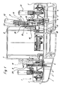
- the terminal block 1 shown in side view in Figure 1 is usually from a large number of lined up, assembled Connection disks 2 formed, seen on Figure 1 in the drawing depth lie side by side.
- Each of the connection plates 2 carries in an electrical insulating plastic housing 3 connections 4 for connection electrical conductor, which in the illustrated embodiment Busbar pieces 5 are connected to plug connections 6.
- An electronic module 7 is also provided, which is connected to the terminal block 1, formed by the connecting plates 2, electrical and is mechanically pluggable.
- the mechanical connection happens in the usual way by inserting appropriately designed housing areas of the housing 8 of the electronics module 7 into a corresponding one Receiving recess in the terminal block 2, which are lined up by the Plastic housing 3 of the connecting plate 2 is formed.
- the plug connection is appropriately mechanically locked.
- this separating device is a separating piece 9, in which both the connector 10 for insertion into the plug connections 6 of the terminal block 1 and thus for electrical Connection between terminal block 1 and electronics module 7, as also test plug connections 11 for inserting a test plug 12 are located.
- the separator 9 is between a closed position and a separation position displaceable on the electronics module 7 captive held.
- the separators are directly in the connector zone of the electronics module 7 provided on this.
- You have a case 13, which engages around the lower edge of the housing 8 of the electronic module 7 and therefore one with the inside of the electronics module housing 8 Section 14 and an outer wall portion 15, which extends in the vertical direction of the electronic module 7.
- the outside lying section 15 includes in its lower end region the connectors 10 with the corresponding plug connections 6 of the connecting disks 2 of the terminal block 1 cooperate. In the upper end region of this section 15 there are upwards open, the test plug connections 11.
- the plug connections are located 6 of the terminal block 1 related to this electronics module 7 outside. This means that this terminal block 1 also if necessary with other electronic modules without a separator can be equipped. These electronic modules would then be so wide that Plug connections or directly the correspondingly designed ends of functional circuit boards inserted directly into the plug connections 6 can be. There is also the option of an electronic module to use, which carries a separator 9 on only one side, while the other side compared to the illustrated embodiment widened accordingly and for direct electrical contacting the plug connections 6 there is set up.
- they include in the separator 9 arranged connector 10 a downward, on the plug connection 6 directional flag 16, located on a track piece 17 is located, from which a contact tab 18 for the Contacting with the pin of the test plug 12 comes off, and from that down another busbar piece 19 goes down to the with respect to the electronics module 7 inner wall portion 14 of the separator 9 runs and here in the interior of the electronics module in the illustrated Embodiment directly contacting the corresponding designed end of a functional circuit board 20 can contact.
- the separator 9 is a sliding contact configuration between the closed position and the disconnected position intended.
- the captive is relocatable Holding the separator 9 on the lower outer wall area of the Housing 8 of the electronics module 7 is achieved in that the wall sections 14 and 15 of the housing 13 of the separator 9 between them define a guide gap 21 into which the lower outer wall area of the housing 8 of the electronics module 7 occurs, so that the separator 9 on the housing 8 can move up and down.
- the wall section concerned of the housing 8 of the electronics module 7 in the height direction from each other recesses 22 and 23 are provided.
- Figures 1 and 2 show the right separator seen on the drawing 9 in its disconnected position.
- the locking hooks 24 and 25 are located in the recesses 22 and 23.
- the electrical connection between the electronics module 7 and the terminal block 2 is separated because the plug-in tabs 16 of the separator 9 upwards from the plug connections 6 are pulled out.
- the separator 9 is essentially a depth extension has according to the terminal block 1 and so many in it electrical connectors 10 are arranged, such as plug connections 6 for the electrical contact between the electrical module 7 and the terminal block 1 are to be made.
- the electronics can now be operated in the raised position by inserting one or more test plugs 12 into the corresponding ones Test connector 11 of the separator 9 are checked.
- This consists essentially of the shown Embodiment molded on the housing 13 of the separator 9 angular springs 26 with their lower legs in a further recess 27 provided for this purpose in the corresponding wall section of the housing 8 of the electronics module 7 enter blocking can.
- the arrangement is such that the spring piece 26 in Rest position on its side facing away from the electronics housing 7 in the test connector 11 protrudes so far that the pin of the test connector 12 automatically when the spring piece 26 is inserted into the Blocking position presses.
- the separators 9 remain regardless of their position on the electronics module.
- the outer-walled section 15 of the housing 13 of the separator 9 expediently as long upwards extends that the upper end also in the closed position of the Partition 9 still clearly visible and manageable above the Wiring level of the connection block 1 is and that too still offers the opportunity to save space and space close to the Separator 9 (see left side of Figure 1) a cross connector comb 28 to provide a potential transverse distribution by contacting of the adjacent conductor rail pieces 5 in the connecting disks 2 of the Terminal block 1 allows.
- the housing 13 of the separator 9 is also useful on the top provided with a bracket or hook piece 29, which the handling the separating piece 9, for example with the aid of a screwdriver, serves.
- the vertical extension of the housing 13 also ensures the good visibility and accessibility of this upper separator end for actuation and, in the upper disconnected position of the separator 9, a comfortable to use, visually well visible and clearly above the wiring level of the terminal block 1 lying plug-in for the test plug 12. The latter applies even if In addition to testing the electronics, a field device test is also useful takes place and in addition to the test plugs 12 for the Electronics test also spatially offset laterally downwards in corresponding plug connections 30 of the connecting disks 2 of the Terminal block 1 test plug 31 can be inserted.
Abstract
Description
Die Erfindung betrifft einen Anschlußklemmenblock mit einem damit elektrisch und mechanisch steckverbindbaren Elektronikmodul und einer an dem Elektronikmodul angebrachten Trenneinrichtung in der elektrisch leitenden Verbindung zwischen dem Anschlußklemmenblock und dem Elektronikmodul. Bei einem bekannten derartigen Anschlußklemmenblock (DE 41 21 836 C2) befindet sich die Trenneinrichtung im oberen Bereich des Moduls. Sie liegt damit zwar gut sichtbar deutlich oberhalb der Verdrahtungsebene des Anschlußklemmenblocks, doch müssen hierzu Stromschienenstücke im Elektronikmodul weit nach oben geführt und auch wieder von dort abgeführt werden. Es ist eine recht komplexe Trennstelle für ausschließlich diese Trennfunktion zu schaffen und es sind bei der dortigen Ausgestaltung besondere, zur Trennstelle führende Steckanschlüsse für Prüfstecker im Gehäuse des Elektronikmoduls zu schaffen.The invention relates to a terminal block with a so electrically and mechanically pluggable electronic module and one on the electronic module attached separator in the electrical conductive connection between the terminal block and the Electronics module. In a known terminal block of this type (DE 41 21 836 C2) the separating device is located in the upper area of the module. It is clearly visible above the Wiring level of the terminal block, but must do this Conductor rail pieces in the electronics module are led far up and also be removed again from there. It is a fairly complex separation point to create only this separation function and there are at the design there special plug connections leading to the separation point for test plugs in the housing of the electronics module.
Der vorliegenden Erfindung liegt von daher die Aufgabe zugrunde, einen derartigen Anschlußklemmenblock zu schaffen, der mit denkbar geringem baulichen Aufwand und geringem Platzbedarf die Trenn- und Prüffunktion ermöglicht.The present invention is therefore based on the object to create such terminal block, with the smallest possible the separation and testing function enables.
Die erfindungsgemäße Lösung besteht im wesentlichen darin, daß die Trenneinrichtung ein ein die elektrischen Steckverbinder des Elektronikmoduls zur elektrischen Verbindung zum Anschlußklemmenblock und Prüfsteckeranschlüsse beinhaltendes Trennstück ist, das in der Steckverbindungszone des Elektronikmoduls an diesem zwischen einer Schließ- und einer Trennstellung verlagerbar gehalten ist. Dadurch, daß die Trenneinrichtung nunmehr in der Steckverbindungszone des Elektronikmoduls liegt, entfallen gesonderte, zu einer Trennstelle führende Stromschienen und dergleichen, dies umso mehr, als dieses Trennstück zugleich auch für den Elektronikmodul Steckverbinderfunktion hat und im übrigen auch direkt aus sich heraus das Einstecken des Prüfsteckers zur Prüfung der Elektronik im Modul ermöglicht. Bei eingestecktem Elektronikmodul gewährleistet das Trennstück somit in seiner Schließstellung die elektrische Steckverbindung an dieser Stelle zwischen dem Elektronikmodul und dem Anschlußklemmenblock. In der Trennstellung ist die elektrische Verbindung an dieser Stelle zum Anschlußklemmenblock unterbrochen und man kann dann durch Einstecken des Prüfsteckers in das Trennstück die gewünschte Prüfung der Elektronik im Modul durchführen. Bei Entnahme des Elektronikmoduls bleibt das Trennstück am Elektronikmodul haften, da es an ihm gehalten ist.The solution according to the invention consists essentially in that the Disconnector a the electrical connector of the Electronic module for electrical connection to the terminal block and test plug connections containing separator, which is in the Connector zone of the electronic module on this between one Closed and a separating position is kept displaceable. Thereby, that the separator is now in the connector zone of the Electronic module is, separate, to a separation point leading busbars and the like, all the more so than this Separator also for the electronics module connector function has and the plugging in of the Test plug for testing the electronics in the module. At inserted electronics module ensures the separator in its closed position the electrical connector at this point between the electronics module and the terminal block. In the Disconnection position is the electrical connection at this point to the Terminal block interrupted and can then be plugged in the test plug into the separator the desired test of the electronics perform in the module. This remains when the electronics module is removed Adhere the separator to the electronics module as it is held on it.
Gemäß einer besonders zweckmäßigen Ausgestaltung eines derartigen Anschlußklemmenblockes ist eine zwischen dem Trennstück und dem Gehäuse des Elektronikmoduls wirkende Blockiervorrichtung vorgesehen, die in der Trennstellung des Trennstückes durch Einstecken des Prüfsteckers betätigbar ist. Damit ist zuverlässig gewährleistet, daß nicht etwa durch Einstecken des Prüfsteckers zu Prüfzwecken das Trennstück dabei wieder in die Schließstellung zurückgedrückt wird.According to a particularly expedient embodiment of such a Terminal block is one between the separator and the housing of the electronic module acting blocking device provided in the separating position of the separator by inserting the test plug can be actuated. This reliably ensures that not by inserting the test plug for test purposes the separator is pushed back into the closed position.
Gemäß einer weiteren bevorzugten Ausgestaltung erstreckt sich das Trennstück zumindest mit einem Teilbereich an einem unteren Außenwandbereich des Elektronikmoduls in dessen Höhenrichtung und trägt im unteren, dem Anschlußklemmenblock zugewandten Endbereich die Steckverbinder des Elektronikmoduls. Dazu werden auch die Steckverbinder im Anschlußklemmenblock, bezogen auf den Elektronikmodul, relativ weit nach außen gelegt, damit die Steckverbinder zusammenwirken können. Es ergibt sich hieraus der Vorteil, daß mit dem Anschlußklemmenblock wahlweise Elektronikmodule mit Trenneinrichtung und Elektronikmodule breiterer Bauweise ohne Trenneinrichtung eingesetzt werden können.According to a further preferred embodiment, this extends Separator at least with a partial area on a lower outer wall area of the electronics module in its height direction and carries in the lower end area facing the terminal block the connectors of the electronics module. The connectors are also used in the terminal block, relative to the electronics module, relatively far placed outside so that the connectors can work together. This has the advantage that with the terminal block optionally electronic modules with isolating device and electronic modules wider construction can be used without a separator.
In weiterer zweckmäßiger Ausgestaltung befinden sich in dem genannten Teilbereich des Trennstückes in dessen Oberseite die Prüfsteckeranschlüsse. In diesem oberen Bereich kann das Trennstück auch als Handhabe ausgebildet sein. Hierdurch läßt sich ein ausreichender Abstand zur Verdrahtungsebene des Anschlußklemmenblockes erreichen, so daß das Trennstück gut sichtbar und gut handhabbar bleibt und auch der Prüfstecker handhabungsbequem in das Trennstück eingesteckt werden kann, zumal sich Letzteres dabei ja in der oberen Trennstellung befindet.In a further expedient embodiment are in the above Part of the separator in the upper side of the test plug connections. In this upper area, the separator can also be used as Handle be trained. This allows a sufficient distance to the wiring level of the terminal block so that the separator remains clearly visible and easy to handle and also the Test plugs can be easily inserted into the separator can, especially since the latter is in the upper separation position located.
Ein Ausführungsbeispiel eines erfindungsgemäßen Anschlußklemmenblockes wird nachstehend unter Bezugnahme auf die Zeichnung näher beschrieben. Es zeigen
- Figur 1
- einen Anschlußklemmenblock mit aufgestecktem Elektronikmodul in teilweiser Schnittdarstellung mit einem Trennstück in der Trenn- und Prüfstellung und einem Trennstück in der Schließstellung,
Figur 2- eine Teilansicht der Anordnung nach Figur 1 mit Darstellung des Trennstückes in der Trenn- und Prüfstellung sowie der angrenzenden Bereiche des Elektronikmoduls und des Anschlußklemmenblockes in vergrößertem Maßstab.
- Figure 1
- a terminal block with attached electronic module in partial sectional view with a separator in the disconnect and test position and a separator in the closed position,
- Figure 2
- a partial view of the arrangement of Figure 1 showing the separator in the disconnect and test position and the adjacent areas of the electronics module and the terminal block on an enlarged scale.
Der in Figur 1 in Seitenansicht gezeigte Anschlußklemmenblock 1 ist
üblicherweise aus einer Vielzahl aneinandergereihter, zusammengesetzter
Anschlußscheiben 2 gebildet, die gesehen auf Figur 1 in Zeichnungstiefe
nebeneinander liegen. Jede der Anschlußscheiben 2 trägt in einem elektrisch
isolierenden Kunststoffgehäuse 3 Anschlüsse 4 zum Anschließen
elektrischer Leiter, die im dargestellten Ausführungsbeispiel über
Stromschienenstücke 5 mit Steckanschlüssen 6 verbunden sind.
Vorgesehen ist ferner ein Elektronikmodul 7, der mit dem Anschlußklemmenblock
1, gebildet durch die Anschlußscheiben 2, elektrisch und
mechanisch steckverbindbar ist. Die mechanische Verbindung geschieht
in üblicher Weise durch das Einstecken entsprechend gestalteter Gehäusebereiche
des Gehäuses 8 des Elektronikmoduls 7 in eine entsprechende
Aufnahmeausnehmung im Anschlußklemmenblock 2, die durch die aneinandergereihten
Kunststoffgehäuse 3 der Anschlußscheibe 2 gebildet wird.
Die Steckverbindung wird zweckmäßig mechanisch verrastet.The terminal block 1 shown in side view in Figure 1 is
usually from a large number of lined up, assembled
Es ist ferner eine Trenneinrichtung in der elektrischen Verbindung
zwischen dem Elektronikmodul 7 und dem Anschlußklemmenblock 2 vorgesehen.
Diese Trenneinrichtung ist erfindungsgemäß ein Trennstück 9,
in dem sich sowohl die Steckverbinder 10 zum Einsetzen in die Steckanschlüsse
6 des Anschlußklemmenblockes 1 und damit zur elektrischen
Verbindung zwischen Anschlußklemmenblock 1 und Elektronikmodul 7, als
auch Prüfsteckeranschlüsse 11 zum Einstecken eines Prüfsteckers 12
befinden. Das Trennstück 9 ist dabei zwischen einer Schließstellung
und einer Trennstellung verlagerbar am Elektronikmodul 7 unverlierbar
gehalten. Die Trennstücke sind unmittelbar in der Steckverbindungszone
des Elektronikmoduls 7 an diesem vorgesehen. Sie haben ein Gehäuse
13, das die Unterkante des Gehäuses 8 des Elektronikmodules 7 umgreift
und von daher einen bezüglich des Elektronikmodulgehäuses 8 innenwandigen
Abschnitt 14 sowie einen außenwandigen Abschnitt 15 hat, der
sich in Höhenrichtung des Elektronikmodules 7 erstreckt. Der außen
liegende Abschnitt 15 beinhaltet dabei in seinem unteren Endbereich
die Steckverbinder 10, die mit den entsprechenden Steckanschlüssen
6 der Anschlußscheiben 2 des Anschlußklemmenblockes 1 zusammenwirken.
Im oberen Endbereich dieses Abschnittes 15 befinden sich, nach oben
offen, die Prüfsteckeranschlüsse 11.It is also a disconnector in the electrical connection
provided between the
Durch die vorstehend geschilderte Ausgestaltung liegen die Steckanschlüsse
6 des Anschlußklemmenblockes 1 bezogen auf diesen Elektronikmodul
7 außenseitig. Dies bedeutet, daß dieser Anschlußklemmenblock 1
auch im Bedarfsfall mit anderen Elektronikmodulen ohne Trenneinrichtung
bestückt werden können. Diese Elektronikmodule wären dann so breit, daß
Steckanschlüsse oder unmittelbar die entsprechend ausgestalteten Enden
von Funktionsleiterplatten direkt in die Steckanschlüsse 6 gesteckt
werden können. Es besteht auch die Möglichkeit, einen Elektronikmodul
zu verwenden, der nur auf einer Seite ein Trennstück 9 trägt, während
die andere Seite gegenüber dem dargestellten Ausführungsbeispiel dann
entsprechend verbreitert und für die direkte elektrische Kontaktierung
der dortigen Steckanschlüsse 6 eingerichtet ist.Due to the design described above, the plug connections are located
6 of the terminal block 1 related to this
Im dargestellten Ausführungsbeispiel beinhalten die in dem Trennstück
9 angeordnete Steckverbinder 10 eine nach unten weisende, auf den Steckanschluß
6 gerichtete Steckfahne 16, die sich an einem Stromschienenstück
17 befindet, von dem nach oben eine Kontaktfahne 18 für die
Kontaktierung mit dem Stift des Prüfsteckers 12 abgeht, und von dem
nach unten ein weiteres Stromschienenstück 19 abgeht, das bis in den
bezüglich des Elektronikmodules 7 innenwandigen Abschnitt 14 des Trennstückes
9 verläuft und hier im Inneren des Elektronikmodules im dargestellten
Ausführungsbeispiel direkt das entsprechend kontaktierend
gestaltete Ende einer Funktionsleiterplatte 20 kontaktieren kann.
Im Hinblick auf das Erfordernis der Verlagerbarkeit des Trennstückes
9ist zwischen Schließstellung und Trennstellung insoweit eine Schleifkontaktausgestaltung
vorgesehen.In the illustrated embodiment, they include in the
Im dargestellten Ausführungsbeispiel ist die unverlierbare, verlagerbare
Halterung des Trennstückes 9 am unteren Außenwandungsbereich des
Gehäuses 8 des Elektronikmodules 7 dadurch erreicht, daß die Wandabschnitte
14 und 15 des Gehäuses 13 des Trennstückes 9 zwischen sich
einen Führungsspalt 21 definieren, in den der untere Außenwandbereich
des Gehäuses 8 des Elektronikmodules 7 eintritt, so daß sich das Trennstück
9 am Gehäuse 8 auf- und abwärts verschieblich führen kann. Dabei
sind im dargestellten Ausführungsbeispiel in dem betroffenen Wandabschnitt
des Gehäuses 8 des Elektronikmodules 7 in Höhenrichtung abständig
voneinander Rastausnehmungen 22 und 23 vorgesehen.In the illustrated embodiment, the captive is relocatable
Holding the
Zum Zusammenwirken mit der oberen Rastausnehmung 22 trägt der innenwandige
Abschnitt 14 des Trennstückgehäuses 13 Rasthaken 24, während
zum Zusammenwirken mit der unteren Rastausnehmung 23 der außenwandige
Abschnitt 15 des Trennstückgehäuses 13 Rasthaken 25 hat. To cooperate with the
Die Figuren 1 und 2 zeigen das gesehen auf die Zeichnung rechte Trennstück
9 in seiner Trennstellung. Die Rasthaken 24 und 25 befinden sich
in den Rastausnehmungen 22 und 23. Die elektrische Verbindung zwischen
dem Elektronikmodul 7 und dem Anschlußklemmenblock 2 ist getrennt, da
die Steckfahnen 16 des Trennstückes 9 nach oben aus den Steckanschlüssen
6 herausgezogen sind.Figures 1 and 2 show the right separator seen on the
Es versteht sich, daß das Trennstück 9 im wesentlichen eine Tiefenerstreckung
entsprechend dem Anschlußklemmenblock 1 hat und in ihm soviele
elektrische Steckverbinder 10 angeordnet sind, wie Steckanschlüsse 6
für die elektrische Kontaktierung zwischen Elektromodul 7 und Anschlußklemmenblock
1 zu tätigen sind.It is understood that the
In der genannten hochgezogenen Trennstellung kann nun die Elektronik
durch Einstecken ein oder mehrerer Prüfstecker 12 in den entsprechenden
Prüfsteckeranschluß 11 des Trennstückes 9 geprüft werden. Um sicherzustellen,
daß sich das Trennstück 9 durch Einstecken der Prüfstecker
12 trotz der Verrastung nicht doch noch wieder nach unten in die
Schließstellung bewegen kann, ist zusätzlich eine besondere Blockiervorrichtung
vorgesehen. Diese besteht im wesentlichen aus im dargestellten
Ausführungsbeispiel am Gehäuse 13 des Trennstückes 9 angeformten
winkelförmigen Federn 26, die mit ihren unteren Schenkeln in
eine dafür vorgesehene weitere Ausnehmung 27 im entsprechenden Wandabschnitt
des Gehäuses 8 des Elektronikmodules 7 blockierend eintreten
können. Die Anordnung ist dabei so getroffen, daß das Federstück 26 in
Ruhestellung auf seiner dem Elektronikgehäuse 7 abgewandten Seite in
den Prüfsteckeranschluß 11 so weit vorsteht, daß der Stift des Prüfsteckers
12 beim Einstecken das Federstück 26 automatisch in die
Blockierstellung drückt.The electronics can now be operated in the raised position
by inserting one or
In der in Figur 1 auf der linken Seite illustrierten Schließstellung
des Trennstückes 9 ist dieses so weit nach unten gedrückt, daß sich
zur elektrischen Verbindung des Anschlußblockes 1 mit dem Elektronikmodul
7 die Steckfahnen 16 der elektrischen Steckverbinder 10 des Trennstückes
9 in eingesteckter Kontaktlage zu den Steckanschlüssen 6 befinden.
In dieser Lage befinden sich die Rasthaken 24 am innen liegenden
Abschnitt 14 des Trennstückgehäuses 13 nunmehr in den unteren Rastausnehmungen
24 der Wandung des Gehäuses 8 des Elektronikmodules 7.
Die Rasthaken 25 des außenwandigen Abschnittes 15 liegen außerhalb
unterhalb des Gehäuses 8.In the closed position illustrated on the left in FIG. 1
of the
Beim Abnehmen des Elektronikmodules 7 verbleiben die Trennstücke 9
unabhängig von ihrer jeweiligen Stellung am Elektronikmodul.When the
Wie aus den Figuren ersichtlich, wird der außenwandige Abschnitt 15
des Gehäuses 13 des Trennstückes 9 zweckmäßig so lang nach oben
erstreckt, daß sich das obere Ende auch in der Schließstellung des
Trennstückes 9 noch gut sichtbar und handhabbar oberhalb der
Verdrahtungsebene des Anschlußblockes 1 befindet und daß sich auch
noch die Möglichkeit bietet, platzsparend und räumlich eng neben dem
Trennstück 9 (siehe linke Seite der Figur 1) einen Querverbinderkamm
28 vorzusehen, der eine Potentialquerverteilung durch Kontaktierung
der benachbarten Stromschienenstücke 5 in den Anschlußscheiben 2 des
Anschlußklemmenblockes 1 ermöglicht.As can be seen from the figures, the outer-
Das Gehäuse 13 des Trennstückes 9 ist ferner zweckmäßig an der Oberseite
mit einem Bügel- oder Hakenstück 29 versehen, das der Handhabung
des Trennstückes 9, beispielsweise mit Hilfe eines Schraubendrehers,
dient. Die Höhenerstreckung des Gehäuses 13 gewährleistet dabei auch
die gute Sichtbarkeit und Zugänglichkeit dieses oberen Trennstückendes
zwecks Betätigung und, in der oberen Trennstellung des Trennstückes
9,eine handhabungsbequeme, optisch gut sichtbare und deutlich oberhalb
der Verdrahtungsebene des Anschlußklemmenblockes 1 liegende Einsteckmöglichkeit
für die Prüfstecker 12. Letzteres gilt selbst dann, wenn
zweckmäßig neben der Prüfung der Elektronik auch eine Feldgeräteprüfung
stattfindet und hierzu neben den Prüfsteckern 12 für die
Elektronikprüfung auch räumlich dazu seitlich nach unten außen versetzt
in entsprechenden Steckanschlüssen 30 der Anschlußscheiben 2 des
Anschlußklemmenblockes 1 Prüfstecker 31 eingesteckt werden.The
Claims (11)
- A connecting terminal block (1) with an electronic module (7) electrically and mechanically pluggable thereto and a disconnect device (9) arranged on the electronic module (7) in the electrical connection between the connecting terminal block (1) and the electronic module (7), characterised in that the disconnect device is a disconnect portion (9) which includes the electrical plug connectors (10) of the electronic module (7) for electrical connection to the connecting terminal block (1) and test plug connections (11) and which in the plug connection zone of the electronic module (7) is held thereon displaceably between a closed position and a disconnect position.
- A connecting terminal block according to claim 1 characterised by a blocking device (26, 27) which is operative between the disconnect portion (9) and the housing (8) of the electronic module (7) and which is actuable in the disconnect position of the disconnect portion (9) by the insertion of a test plug (12).
- A connecting terminal block according to one of the preceding claims characterised in that the housing (13) of the disconnect portion (9) has a part (15) which extends on the outside wall of the housing (8) of the electronic module (7) in the direction of the height thereof and in the lower region of which are disposed the electrical plug connectors (10), for which plug connections (6) are provided at a corresponding, oppositely disposed location in the connecting terminal block (1).
- A connecting terminal block according to claim 3 characterised in that the test plug connections (11) are provided on the part (15) of the housing (13) of the disconnect portion (9) in the upper end region thereof.
- A connecting terminal block according to one of the preceding claims characterised in that the housing (13) of the disconnect portion (9), engaging over the lower edge of an outside wall of the housing (8) of the electronic module (7), has a part (14) which is disposed inwardly with respect to the electronic module housing (8) and an outwardly disposed part (15), which form between them a guide gap (21) for said wall region of the housing (8) of the electronic module (7).
- A connecting terminal block according to claim 5 characterised in that provided in the wall region, which co-operates with the disconnect portion (9), of the housing (8) of the electronic module (7) at a spacing above each other in the heightwise direction are retaining openings (22, 23) for which retaining hooks (24, 25) are provided at a corresponding spacing from each other on the housing (13) for the purposes of holding the disconnect portion (9) to the electronic module (7) and for the purposes of securing the closed and disconnect position of the disconnect portion (9).
- A connecting terminal block according to claim 2 characterised in that the blocking device is formed from spring portions (26) which are provided on the disconnect portion (9) and which project in their rest position into test plug connections (11) of the disconnect portion (9) and which are resiliently displaceable in the direction of the wall of the housing (8) of the electronic module (7), wherein openings (27) blockingly receiving them are provided in a suitable position in the wall.
- A connecting terminal block according to one of the preceding claims characterised in that the plug connectors (10) in the disconnect portions (9) have plug lugs (16) which face downwardly towards the plug connections (6) of the connecting terminal block (1) and which are carried on current bar portions (17) from which a contact lug (18) for the test plug connection branches off upwardly and from which there branches off downwardly a further current bar portion (19) which extends into the part (14) of the disconnect portion (9) disposed at the inside wall with respect to the electronic module housing (8) and is here in the form of a contact in relation to the electronics of the electronic module (7).
- A connecting terminal block according to claim 1 characterised in that the connecting terminal block (1) which is composed of individual connecting plates (2) has in the connecting plates (2) in spatially adjacent relationship to the disconnect portion (9) plug receiving means for a cross-connector comb (28).
- A connecting terminal block according to claim 9 characterised in that the part (15) of the housing (13) of the disconnect portion (9), which part is disposed at the outside wall in relation to the electronic module (7), is extended upwardly in the direction of height to such an extent that there remains adjacent thereto even in its closed position a free space for the cross-connector comb (28).
- A connecting terminal block according to one of the preceding claims characterised by heightwise displaceability of the disconnect portion (9) and a position in respect of height of the test plug connections (11) such that in the disconnect position of the disconnect portion (9) inserted test plugs are disposed in heightwise-displaced relationship above test plugs (31) which are inserted into laterally outwardly adjacent test connections (30) of the connecting terminal block (1).
Applications Claiming Priority (2)
| Application Number | Priority Date | Filing Date | Title |
|---|---|---|---|
| DE4438800A DE4438800C1 (en) | 1994-10-31 | 1994-10-31 | Connection terminal block for electronic modules |
| DE4438800 | 1994-10-31 |
Publications (3)
| Publication Number | Publication Date |
|---|---|
| EP0709917A2 EP0709917A2 (en) | 1996-05-01 |
| EP0709917A3 EP0709917A3 (en) | 1998-03-04 |
| EP0709917B1 true EP0709917B1 (en) | 1999-03-24 |
Family
ID=6532088
Family Applications (1)
| Application Number | Title | Priority Date | Filing Date |
|---|---|---|---|
| EP95113807A Expired - Lifetime EP0709917B1 (en) | 1994-10-31 | 1995-09-02 | Terminal block with electronic module |
Country Status (6)
| Country | Link |
|---|---|
| US (1) | US5588881A (en) |
| EP (1) | EP0709917B1 (en) |
| JP (1) | JP3853408B2 (en) |
| AT (1) | ATE178164T1 (en) |
| DE (2) | DE4438800C1 (en) |
| ES (1) | ES2129165T3 (en) |
Families Citing this family (34)
| Publication number | Priority date | Publication date | Assignee | Title |
|---|---|---|---|---|
| DE4440102C1 (en) * | 1994-11-10 | 1996-05-15 | Weidmueller Interface | Modular control system with integrated fieldbus connection |
| FR2732518B1 (en) * | 1995-03-29 | 1997-04-30 | Entrelec Sa | CONNECTION ARRANGEMENT FOR ELECTRICAL CONDUCTIVE WIRES AND MODULE, IN PARTICULAR OF THE JUNCTION BLOCK TYPE, EQUIPPED WITH SUCH AN ARRANGEMENT |
| US5890934A (en) * | 1997-09-30 | 1999-04-06 | Weidmuller Inc. | Pluggable connector assembly for printed circuit boards |
| FR2773914B1 (en) * | 1998-01-21 | 2000-04-21 | Entrelec Sa | ELECTRICAL CONNECTION BLOCK WITH INTERCONNECTION PIECE ACCESSIBLE THROUGH A TEST SOCKET AND INTERCONNECTION PIECE FOR SUCH A BLOCK |
| DE29804284U1 (en) * | 1998-03-11 | 1998-05-07 | Weidmueller Interface | Control system for electronic control and automation systems |
| DE29806691U1 (en) | 1998-04-15 | 1998-05-28 | Weidmueller Interface | Mounting foot for modular housing or clamps |
| FR2777702B1 (en) * | 1998-04-17 | 2000-06-16 | Entrelec Sa | SELF-STRIPPING CONNECTION DEVICE |
| US6220901B1 (en) * | 1998-04-30 | 2001-04-24 | General Electric Company | Electric motor terminal board assembly |
| US6074241A (en) * | 1998-06-05 | 2000-06-13 | The Whitaker Corporation | Non-slip spring clamp contact |
| DE19964157A1 (en) * | 1999-01-25 | 2000-10-05 | Weidmueller Interface | Electric device |
| DE29901194U1 (en) | 1999-01-25 | 1999-05-20 | Weidmueller Interface | Bus conductor section for an electrical device |
| DE29910179U1 (en) * | 1999-06-11 | 2000-11-02 | Weidmueller Interface | Connectors for electrical controls |
| DE29916303U1 (en) | 1999-09-16 | 2001-02-22 | Weidmueller Interface | Module with coupling elements |
| DE10011385A1 (en) * | 2000-03-09 | 2001-09-13 | Abb Cmc Carl Maier Ag Schaffha | Installation device for electrical low voltage installations, has bottom for fixing into installation and bearing connection terminals, and functional modules, each accepting 1 of 2 active parts |
| DE10045498C5 (en) * | 2000-09-13 | 2006-06-08 | Phoenix Contact Gmbh & Co. Kg | Electrical terminal block |
| DE20106710U1 (en) * | 2001-04-18 | 2001-08-09 | Phoenix Contact Gmbh & Co | Electrical clamp |
| DE20211002U1 (en) | 2002-07-19 | 2003-12-04 | Weidmüller Interface Gmbh & Co. | Module for an electrical device, in particular fieldbus module |
| DE102004043466B4 (en) * | 2004-09-08 | 2007-08-02 | Siemens Ag | Power supply module with cage spring clamp terminals |
| DE102005017712A1 (en) * | 2005-04-15 | 2006-12-14 | Abb Patent Gmbh | automation system |
| DE102006030953A1 (en) * | 2005-08-17 | 2007-03-15 | Abb Patent Gmbh | Electrical device, in particular line residual current or motor protection switch |
| DE102005040657A1 (en) * | 2005-08-26 | 2007-03-15 | Phoenix Contact Gmbh & Co. Kg | Electrical connection terminal |
| DE102005043878A1 (en) * | 2005-09-14 | 2007-03-22 | Wöhner GmbH & Co. KG Elektrotechnische Systeme | Busbar connection module |
| DE102006053352B3 (en) * | 2006-11-10 | 2008-04-17 | Phoenix Contact Gmbh & Co. Kg | Insert, has two spring legs which are components of leg springs connected to each other by bent joint and stayed together at obtuse angle, where one spring leg is inactive and extends inside region of mounting units |
| DE202007005373U1 (en) * | 2007-04-12 | 2008-08-21 | Weidmüller Interface GmbH & Co. KG | Modular terminal block system |
| DE102007059640B4 (en) * | 2007-12-10 | 2009-11-26 | Wago Verwaltungsgesellschaft Mbh | connection module |
| EP2554030B1 (en) * | 2010-03-31 | 2017-03-15 | Weidmüller Interface GmbH & Co. KG | Connection module being capable of serving as a bus |
| DE102011087209B4 (en) * | 2011-11-28 | 2019-02-28 | Siemens Aktiengesellschaft | Electrical installation equipment |
| TW201507300A (en) * | 2013-08-07 | 2015-02-16 | Switchlab Inc | Wire terminal seat improvement structure |
| EP3105827A4 (en) | 2014-02-13 | 2017-11-15 | Erico International Corporation | Disconnect splice block and modular surge device |
| DE102014105316A1 (en) | 2014-04-14 | 2015-10-15 | Weidmüller Interface GmbH & Co. KG | Modular terminal block |
| FR3026238B1 (en) * | 2014-09-23 | 2016-10-21 | Abb France | PART OF CONDUCTIVE BAR FOR AN ELECTRICAL APPLIANCE |
| DE202017106533U1 (en) * | 2017-10-27 | 2019-01-30 | Wago Verwaltungsgesellschaft Mbh | Electrical terminal block |
| DE102018109861A1 (en) * | 2018-04-24 | 2019-10-24 | Phoenix Contact Gmbh & Co. Kg | Connector assembly for a terminal block |
| DE102020001046A1 (en) | 2020-02-18 | 2021-08-19 | Hottinger Baldwin Messtechnik Gesesllschaft mit beschränkter Haftung | DIN rail mounting module for spatially limited control cabinets |
Family Cites Families (7)
| Publication number | Priority date | Publication date | Assignee | Title |
|---|---|---|---|---|
| DE1238087B (en) * | 1965-03-25 | 1967-04-06 | Siemens Ag | Line connector with separation point |
| SE377636B (en) * | 1973-11-12 | 1975-07-14 | Asea Ab | |
| DE3233255C2 (en) * | 1982-09-08 | 1984-09-27 | Phönix Elektrizitätsgesellschaft H. Knümann GmbH & Co KG, 4933 Blomberg | Electrical connection terminal, in particular switchgear terminal block |
| DE3311820C2 (en) * | 1983-03-31 | 1988-10-20 | C.A. Weidmüller GmbH & Co, 4930 Detmold | Terminal block with a swivel lever carrying an electrical active element |
| FR2659118B1 (en) * | 1990-03-02 | 1992-05-07 | Entrelec Sa | DEVICE FOR FIXING A TERMINAL BLOCK ON A SYMMETRICAL SUPPORT PROFILE. |
| DE4121836C2 (en) * | 1991-07-02 | 1994-07-07 | Weidmueller C A Gmbh Co | Terminal block with plug-on module |
| US5407367A (en) * | 1993-09-27 | 1995-04-18 | Vernitron Corporation | Barrier terminal strip assembly |
-
1994
- 1994-10-31 DE DE4438800A patent/DE4438800C1/en not_active Expired - Fee Related
-
1995
- 1995-09-02 AT AT95113807T patent/ATE178164T1/en not_active IP Right Cessation
- 1995-09-02 EP EP95113807A patent/EP0709917B1/en not_active Expired - Lifetime
- 1995-09-02 ES ES95113807T patent/ES2129165T3/en not_active Expired - Lifetime
- 1995-09-02 DE DE59505430T patent/DE59505430D1/en not_active Expired - Lifetime
- 1995-10-18 US US08/544,482 patent/US5588881A/en not_active Expired - Fee Related
- 1995-10-31 JP JP28327395A patent/JP3853408B2/en not_active Expired - Fee Related
Also Published As
| Publication number | Publication date |
|---|---|
| DE59505430D1 (en) | 1999-04-29 |
| EP0709917A2 (en) | 1996-05-01 |
| ES2129165T3 (en) | 1999-06-01 |
| ATE178164T1 (en) | 1999-04-15 |
| JPH08227760A (en) | 1996-09-03 |
| EP0709917A3 (en) | 1998-03-04 |
| US5588881A (en) | 1996-12-31 |
| DE4438800C1 (en) | 1996-01-18 |
| JP3853408B2 (en) | 2006-12-06 |
Similar Documents
| Publication | Publication Date | Title |
|---|---|---|
| EP0709917B1 (en) | Terminal block with electronic module | |
| EP0709920B1 (en) | Modular control system | |
| EP0272200B1 (en) | Connecting block for the telecommunications | |
| WO1997044864A1 (en) | Catch system for a pin-and-socket connector coupling | |
| EP0914029B1 (en) | Modular automation apparatus and unit for a modular automation apparatus | |
| DE4121836A1 (en) | ROW TERMINAL WITH CLIP-ON MODULE | |
| EP0753916A2 (en) | Bus bar adapter system | |
| DE19902745B4 (en) | Electric device | |
| DE102005033998A1 (en) | Insulation displacement connector and device for telecommunications and data technology | |
| EP1113525B1 (en) | Terminal block, especially for measure transformer with transverse shunt arrangement | |
| DE19547557A1 (en) | Electric terminals with pluggable transverse bridges | |
| EP2862364B1 (en) | Distributor connection module | |
| EP3241261A1 (en) | Overvoltage protection arrangement for information and telecommunication technology | |
| EP0477664A1 (en) | Protector plug for distributor board of telephonic equipments, in particular for private branch exchanges | |
| DE10230292B3 (en) | Support for module housing | |
| EP1787358B1 (en) | Power feed module with cage clamp terminals | |
| DE102013111571A1 (en) | Device housing, electronic devices and plug-in contact carrier | |
| EP0262325A2 (en) | Device for a distribution frame | |
| EP0951105B1 (en) | Multiple socket | |
| DE3442625A1 (en) | Overload relay | |
| DE1614401A1 (en) | Electric jack | |
| EP0951104B1 (en) | Socket, particularly a built-in box for electrical installations | |
| DE10338787A1 (en) | Cross connector for terminal blocks | |
| DE10117758A1 (en) | Module for automation equipment e.g. for controlling and regulating processes, includes a movable bus-contacting part for making bus connection with adjacent module | |
| DE7920512U1 (en) | Arrangement for connecting electrical conductors |
Legal Events
| Date | Code | Title | Description |
|---|---|---|---|
| PUAI | Public reference made under article 153(3) epc to a published international application that has entered the european phase |
Free format text: ORIGINAL CODE: 0009012 |
|
| AK | Designated contracting states |
Kind code of ref document: A2 Designated state(s): AT CH DE ES FR GB IT LI |
|
| PUAL | Search report despatched |
Free format text: ORIGINAL CODE: 0009013 |
|
| AK | Designated contracting states |
Kind code of ref document: A3 Designated state(s): AT CH DE ES FR GB IT LI |
|
| 17P | Request for examination filed |
Effective date: 19980210 |
|
| GRAG | Despatch of communication of intention to grant |
Free format text: ORIGINAL CODE: EPIDOS AGRA |
|
| 17Q | First examination report despatched |
Effective date: 19980911 |
|
| GRAG | Despatch of communication of intention to grant |
Free format text: ORIGINAL CODE: EPIDOS AGRA |
|
| GRAH | Despatch of communication of intention to grant a patent |
Free format text: ORIGINAL CODE: EPIDOS IGRA |
|
| ITF | It: translation for a ep patent filed |
Owner name: STUDIO INGG. FISCHETTI & WEBER |
|
| GRAH | Despatch of communication of intention to grant a patent |
Free format text: ORIGINAL CODE: EPIDOS IGRA |
|
| GRAA | (expected) grant |
Free format text: ORIGINAL CODE: 0009210 |
|
| AK | Designated contracting states |
Kind code of ref document: B1 Designated state(s): AT CH DE ES FR GB IT LI |
|
| REF | Corresponds to: |
Ref document number: 178164 Country of ref document: AT Date of ref document: 19990415 Kind code of ref document: T |
|
| REG | Reference to a national code |
Ref country code: CH Ref legal event code: NV Representative=s name: ISLER & PEDRAZZINI AG Ref country code: CH Ref legal event code: EP |
|
| REF | Corresponds to: |
Ref document number: 59505430 Country of ref document: DE Date of ref document: 19990429 |
|
| REG | Reference to a national code |
Ref country code: ES Ref legal event code: FG2A Ref document number: 2129165 Country of ref document: ES Kind code of ref document: T3 |
|
| GBT | Gb: translation of ep patent filed (gb section 77(6)(a)/1977) |
Effective date: 19990602 |
|
| ET | Fr: translation filed | ||
| PLBE | No opposition filed within time limit |
Free format text: ORIGINAL CODE: 0009261 |
|
| STAA | Information on the status of an ep patent application or granted ep patent |
Free format text: STATUS: NO OPPOSITION FILED WITHIN TIME LIMIT |
|
| 26N | No opposition filed | ||
| REG | Reference to a national code |
Ref country code: GB Ref legal event code: IF02 |
|
| REG | Reference to a national code |
Ref country code: CH Ref legal event code: PCAR Free format text: ISLER & PEDRAZZINI AG;POSTFACH 1772;8027 ZUERICH (CH) |
|
| PGFP | Annual fee paid to national office [announced via postgrant information from national office to epo] |
Ref country code: AT Payment date: 20080915 Year of fee payment: 14 |
|
| PGFP | Annual fee paid to national office [announced via postgrant information from national office to epo] |
Ref country code: GB Payment date: 20080918 Year of fee payment: 14 |
|
| GBPC | Gb: european patent ceased through non-payment of renewal fee |
Effective date: 20090902 |
|
| PG25 | Lapsed in a contracting state [announced via postgrant information from national office to epo] |
Ref country code: AT Free format text: LAPSE BECAUSE OF NON-PAYMENT OF DUE FEES Effective date: 20090902 |
|
| PGFP | Annual fee paid to national office [announced via postgrant information from national office to epo] |
Ref country code: ES Payment date: 20100924 Year of fee payment: 16 Ref country code: CH Payment date: 20100923 Year of fee payment: 16 |
|
| PG25 | Lapsed in a contracting state [announced via postgrant information from national office to epo] |
Ref country code: GB Free format text: LAPSE BECAUSE OF NON-PAYMENT OF DUE FEES Effective date: 20090902 |
|
| PGFP | Annual fee paid to national office [announced via postgrant information from national office to epo] |
Ref country code: IT Payment date: 20100922 Year of fee payment: 16 Ref country code: FR Payment date: 20101005 Year of fee payment: 16 |
|
| PGFP | Annual fee paid to national office [announced via postgrant information from national office to epo] |
Ref country code: DE Payment date: 20110923 Year of fee payment: 17 |
|
| REG | Reference to a national code |
Ref country code: CH Ref legal event code: PL |
|
| PG25 | Lapsed in a contracting state [announced via postgrant information from national office to epo] |
Ref country code: IT Free format text: LAPSE BECAUSE OF NON-PAYMENT OF DUE FEES Effective date: 20110902 |
|
| REG | Reference to a national code |
Ref country code: FR Ref legal event code: ST Effective date: 20120531 |
|
| PG25 | Lapsed in a contracting state [announced via postgrant information from national office to epo] |
Ref country code: LI Free format text: LAPSE BECAUSE OF NON-PAYMENT OF DUE FEES Effective date: 20110930 Ref country code: CH Free format text: LAPSE BECAUSE OF NON-PAYMENT OF DUE FEES Effective date: 20110930 |
|
| PG25 | Lapsed in a contracting state [announced via postgrant information from national office to epo] |
Ref country code: FR Free format text: LAPSE BECAUSE OF NON-PAYMENT OF DUE FEES Effective date: 20110930 |
|
| REG | Reference to a national code |
Ref country code: ES Ref legal event code: FD2A Effective date: 20130704 |
|
| PG25 | Lapsed in a contracting state [announced via postgrant information from national office to epo] |
Ref country code: ES Free format text: LAPSE BECAUSE OF NON-PAYMENT OF DUE FEES Effective date: 20110903 Ref country code: DE Free format text: LAPSE BECAUSE OF NON-PAYMENT OF DUE FEES Effective date: 20130403 |
|
| REG | Reference to a national code |
Ref country code: DE Ref legal event code: R119 Ref document number: 59505430 Country of ref document: DE Effective date: 20130403 |