EP1787358B1 - Power feed module with cage clamp terminals - Google Patents
Power feed module with cage clamp terminals Download PDFInfo
- Publication number
- EP1787358B1 EP1787358B1 EP05771942.9A EP05771942A EP1787358B1 EP 1787358 B1 EP1787358 B1 EP 1787358B1 EP 05771942 A EP05771942 A EP 05771942A EP 1787358 B1 EP1787358 B1 EP 1787358B1
- Authority
- EP
- European Patent Office
- Prior art keywords
- feed module
- power feed
- polyphase
- housing
- module according
- Prior art date
- Legal status (The legal status is an assumption and is not a legal conclusion. Google has not performed a legal analysis and makes no representation as to the accuracy of the status listed.)
- Not-in-force
Links
Images


Classifications
-
- H—ELECTRICITY
- H01—ELECTRIC ELEMENTS
- H01R—ELECTRICALLY-CONDUCTIVE CONNECTIONS; STRUCTURAL ASSOCIATIONS OF A PLURALITY OF MUTUALLY-INSULATED ELECTRICAL CONNECTING ELEMENTS; COUPLING DEVICES; CURRENT COLLECTORS
- H01R9/00—Structural associations of a plurality of mutually-insulated electrical connecting elements, e.g. terminal strips or terminal blocks; Terminals or binding posts mounted upon a base or in a case; Bases therefor
- H01R9/22—Bases, e.g. strip, block, panel
- H01R9/24—Terminal blocks
- H01R9/26—Clip-on terminal blocks for side-by-side rail- or strip-mounting
- H01R9/2675—Electrical interconnections between two blocks, e.g. by means of busbars
-
- H—ELECTRICITY
- H01—ELECTRIC ELEMENTS
- H01R—ELECTRICALLY-CONDUCTIVE CONNECTIONS; STRUCTURAL ASSOCIATIONS OF A PLURALITY OF MUTUALLY-INSULATED ELECTRICAL CONNECTING ELEMENTS; COUPLING DEVICES; CURRENT COLLECTORS
- H01R31/00—Coupling parts supported only by co-operation with counterpart
- H01R31/08—Short-circuiting members for bridging contacts in a counterpart
Definitions
- the invention relates to a multi-phase, encapsulated power supply module with a housing having in its interior terminals which are electrically connected to first plug-in terminals, which serve for making electrical contact with a multi-phase power distribution system.
- Such Stromeinspeisemodul is from the EP 1 351 336 known.
- the plug-in module disclosed here has box terminals and a lyre contact electrically connected to each box terminal.
- the Lyrauttone be plugged for electrical connection to a power rail of a multi-phase system.
- a cover must be removed from the power supply module, which ensures contact safety when mounted.
- the electrical connector of the Lyrauttone with the busbars requires that the assembly is done together with serving as a holder Isolierstoffong the Stromeinspeisemoduls.
- the invention has for its object to provide a multi-phase, encapsulated power supply module of the type mentioned above, which allows a particularly simple installation and wiring.
- This invention is given by the features of claim 1.
- the terminals are designed as cage-spring clips, and in which for electrical contacting a bridge connector adapted to the first plug-in connections is provided, by which the first plug-in terminals are electrically connectable to the polyphase power distribution system, and in which Cage tension spring terminals each have a conductor insertion opening Assigned in the housing, and in which the housing is provided for fastening the power supply module with at least one fastening means
- the object underlying the invention can be achieved in that the cage-spring clips are electrically connected to further third and / or fourth plug connections which lie in the interior of the housing and are accessible via a third and / or fourth contacting opening in the housing.
- a further advantageous embodiment is when the power supply module has a mounting side and this the conductor insertion openings are opposite, which facilitates the fitter the connection of feeders. If, in addition, the conductor insertion openings are differently spaced relative to the attachment side, the supply of supply lines is thereby considerably simplified, at least from one side.
- first plug connections are located inside the housing and are accessible via a first contacting opening in the housing, this makes it possible to ensure contact safety in a simple manner.
- This is advantageously carried out in that the bridge connector is adapted to the first contact opening such that it is covered by him after contacting the first plug-in connections.
- cage-spring clips are additionally electrically connected to second plug-in connections, which are located in the interior of the housing, and are accessible via a second contact opening in the housing, so this is another way to connect to a power distribution system.
- the first and the second contacting opening of the power supply module are located on opposite sides of the housing, so that in each case a power distribution system can be connected in a simple manner on both sides.
- At least one of the first, second, third and fourth plug-in connections are designed as busbar sections which enable a simple plug connection.
- jumper plug is designed with Lyra contacts, this makes it particularly easy to connect to busbars.
- the busbar sections are insulated from one another by insulating partitions.
- a further advantageous embodiment of the invention is when the power supply module is electrically connected in the fixed state via its fastening means by means of the bridge plug with a power distribution system and when this electrical connection can only be canceled by removing the jumper plug.
- Another advantage is when the power distribution system is housed in a carrier on which at least one switching device connected to the power distribution system is adapted. If an intervention is provided on the switching device by the fitter, he only needs to pull the jumper plug and can then undertake this engagement on the unlocked switching device safely due to the visible open separation section.
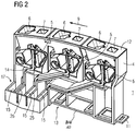
- FIG. 1 is a perspective view of a multi-phase encapsulated power supply module 1 according to the invention for use in the low-voltage switching device technology shown, which serves on the one hand for connection and contacting of the feed lines and for forwarding the current to an electrically coupled multi-phase power distribution system. From the usually implemented as a busbar system power distribution system via switching devices, the connection of consumers.
- a carrier 2 is arranged, in which a busbar system, which is not visible here, is accommodated and has the fastening means 3 for the mechanical adaptation of switching devices.
- the power supply module according to FIG. 1 and 2 is three-phase formed with a housing 4, in the interior of which three designed as a cage-Zugfederklemmen 5 terminals are as shown in the DE 197 11 051 A1 are known.
- the housing 4 of the power supply module 1 has for each cage-Zugfederklemme 5 each at least one conductor insertion opening 6 and an actuating opening 7 for insertion of a tool, such as a screwdriver, with the cage-tension spring clip 5 in the direction of movement-connection direction according to arrow. 9 can be pressed, as the sectional view of the power supply module 1 according to FIG. 2 can be seen.
- the housing 4 has on its attachment side 13 a cutout 10 with associated DIN rail fastening means for snapping onto a top hat rail, for example a slide 11.
- a cutout 10 with associated DIN rail fastening means for snapping onto a top hat rail, for example a slide 11.
- housing wall 12 At the attachment side 13 opposite the fitter facing the fitter after mounting the power feed module 1 housing wall 12 are the conductors -Einlanderö réelleen 6 and the actuating openings 7 in the movement-connection direction according to arrow 9 in series one behind the other.
- the housing wall 12 is not substantially parallel to the mounting side 13, but at an oblique angle, such that the Ladder insertion holes to the mounting side 13 starting from one side have an increasing distance. This facilitates, at least from one side, the introduction of the feed lines in the direction of movement connection according to arrow 9.
- cage-Zugfederklemmen 5 go electrically conductive connections 14 according to FIG. 2 from which terminate in first 15 and / or second plug-in terminals 16, which are designed here as busbar sections (see also FIG. 1, 2 ).
- FIG. 1 . 2 and 3 show the insulated by partition walls 25 from each other busbar sections 15, 16 which lie in the interior of the housing 4 and are accessible via a first 17 and second contacting opening 24 in the housing 4.
- a bridge plug 18 adapted to the first 15 and second plug connections 16 is provided, through which the plug connections 15, 16 are connected to the polyphase power distribution system FIG. 5 are electrically connected.
- the jumper plug 18 is according to FIG. 4 equipped with LyraWalleten 19 as plug contacts for connection to the busbar sections 15, 16.
- the jumper plug 18 with respect to its insulating housing so adapted to the contact hole 17 and 24, that it is covered by him after contacting the plug-in terminals 15 or 16, whereby the required contact safety is provided.
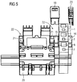
- FIG. 5 the coupling of a power distribution system is shown on one side.
- the bevel of the housing wall 12 with the conductor insertion openings 6 according to FIG. 1 facilitates the introduction of the feed lines from the lying above the DIN rail side on which are also designed as bus bars 16 plug-in connections of the power supply module 1.
- a power supply module 1 which is equipped with third 26 and fourth 27 designed as busbars plug-in connections, which are accessible via a third 28 and fourth contact opening 29. These are used if necessary for rotation of the power supply module 1 by 180 °, so that feed lines from both sides can be easily inserted.
- the power supply module 1 corresponds to FIG FIG. 3 the in FIG. 2 illustrated embodiment with the cage-Zugfederklemmen 5, the conductor insertion openings 6, the actuating openings 7 and the electrically conductive connections fourteenth
- FIG. 5 is a simplified plan view of the power supply module 1 with an adjacent carrier 20 to illustrate the features essential to the invention.
- the carrier 20 busbars 21 of an energy distribution system are integrated.
- the carrier 20 in each case has a contacting opening 22 which is similar to the contacting openings 17 and 24 of the power supply module 1.
- the jumper plug 18 an electrical plug connection between the power supply module 1 and the power distribution system can be produced in a simple manner. Just as simple is the electrical connection can be canceled only by pulling the bridge connector 18, which at the same time the advantage of a visible separation distance for the fitter is given.
- the plug connections not used for the installer are by corresponding covers 23 according to FIG. 5 Coverable with touch.
- enabled Switchgear is then possible by the fitter a safe intervention.
Description
Die Erfindung betrifft ein mehrphasiges, gekapseltes Strom-Einspeisemodul mit einem Gehäuse, das in seinem Inneren Anschlussklemmen aufweist, die mit ersten Steckanschlüssen elektrisch verbunden sind, die zur elektrischen Kontaktierung mit einem mehrphasigen Energieverteilungssystem dienen.The invention relates to a multi-phase, encapsulated power supply module with a housing having in its interior terminals which are electrically connected to first plug-in terminals, which serve for making electrical contact with a multi-phase power distribution system.
Ein derartiges Stromeinspeisemodul ist aus der
Weitere Einspeisesysteme sind durch die
Der Erfindung liegt die Aufgabe zugrunde, ein mehrphasiges, gekapseltes Strom-Einspeisemodul der oben genannten Art zu schaffen, das eine besonders einfache Montage und Verdrahtung ermöglicht. Diese Erfindung ist durch die Merkmale des Anspruchs 1 gegeben.The invention has for its object to provide a multi-phase, encapsulated power supply module of the type mentioned above, which allows a particularly simple installation and wiring. This invention is given by the features of
In einem mehrphasigen, gekapselten Einspeisesystem, in dem die Anschlussklemmen als Käfig-Zugfederklemmen ausgeführtsind, und in dem zur elektrischen Kontaktierung ein an die ersten Steckanschlüsse angepasster Brückenstecker vorgesehen ist, durch den die ersten Steckanschlüsse mit dem mehrphasigen Energieverteilungssystem elektrisch verbindbar sind, und in dem den Käfig-Zugfederklemmen jeweils eine Leiter-Einführöffnung im Gehäuse zugeordnet ist, und in dem das Gehäuse zur Befestigung des Strom-Einspeisemoduls mit mindestens einem Befestigungsmittel versehen ist, kann die der Erfindung zugrunde liegende Aufgabe dadurch gelöst werden, dass die Käfig-Zugfederklemmen mit weiteren dritten und/oder vierten Steckanschlüssen elektrisch verbunden sind, die im Inneren des Gehäuses liegen und über eine dritte und/oder vierte Kontaktierungsöffnung im Gehäuse zugänglich sind. Bei entsprechender Anordnung dieser dritten und vierten Steckanschlüsse wird nämlich ein Strom-Einspeisemodul geschaffen, mit dem durch entsprechende Ausrichtung bei der Montage, d.h. Drehung um 180°, die Zuführung von Einspeiseleitungen sowohl von oben als auch von unten möglich ist.In a multi-phase, encapsulated feed system, in which the terminals are designed as cage-spring clips, and in which for electrical contacting a bridge connector adapted to the first plug-in connections is provided, by which the first plug-in terminals are electrically connectable to the polyphase power distribution system, and in which Cage tension spring terminals each have a conductor insertion opening Assigned in the housing, and in which the housing is provided for fastening the power supply module with at least one fastening means, the object underlying the invention can be achieved in that the cage-spring clips are electrically connected to further third and / or fourth plug connections which lie in the interior of the housing and are accessible via a third and / or fourth contacting opening in the housing. With a corresponding arrangement of these third and fourth plug-in connections, a power supply module is created, with which the supply of supply lines is possible both from above and from below by appropriate alignment during assembly, ie rotation through 180 °.
Die Erfindung ermöglicht, dass folgende drei Funktionen unabhängig voneinander ausgeführt werden können:
- die mechanische Befestigung des Strom-Einspeisemoduls,
- der elektrische Anschluss der Einspeiseleitung und
- die elektrische Verbindung des Strom-Einspeisemoduls mit dem Energieverteilungssystem.
- the mechanical fastening of the power supply module,
- the electrical connection of the feed line and
- the electrical connection of the power supply module with the power distribution system.
Vorteilhafte Weiterbildungen der Erfindung sind den Unteransprüchen zu entnehmen.Advantageous developments of the invention can be found in the dependent claims.
Liegen die Leiter-Einführöffnungen in der Bewegungsanschlussrichtung der Zugfederklemmen in Reihe hintereinander, so wird hiermit eine schmale Bauform eines Strom-Einspeisemoduls erreicht, die in der Anwendung nur geringen Platz beansprucht.If the conductor insertion openings in the direction of movement of the tension spring terminals in series one behind the other, so hereby a narrow design of a power supply module is achieved, which takes up little space in the application.
Eine weitere vorteilhafte Ausführung besteht, wenn das Strom-Einspeisemodul eine Befestigungsseite aufweist und dieser die Leiter-Einführöffnungen gegenüberliegen, was dem Monteur den Anschluss von Einspeiseleitungen erleichtert. Sind darüber hinaus die Leiter-Einführöffnungen gegenüber der Befestigungsseite unterschiedlich beabstandet, so wird hierdurch die Zuführung von Einspeiseleitungen zumindest von einer Seite her wesentlich vereinfacht.A further advantageous embodiment is when the power supply module has a mounting side and this the conductor insertion openings are opposite, which facilitates the fitter the connection of feeders. If, in addition, the conductor insertion openings are differently spaced relative to the attachment side, the supply of supply lines is thereby considerably simplified, at least from one side.
Eine vorteilhafte Weiterbildung besteht, wenn die Leiter-Einführöffnungen in einer Gehäusewand des Strom-Einspeisemoduls liegen, die gegenüber der Befestigungsseite abgeschrägt ist.An advantageous development is when the conductor insertion openings are located in a housing wall of the power supply module, which is beveled relative to the attachment side.
Liegen die ersten Steckanschlüsse im Inneren des Gehäuses und sind über eine erste Kontaktierungsöffnung im Gehäuse zugänglich, ermöglicht dies auf einfache Weise die Berührsicherheit sicherzustellen. Dies erfolgt vorteilhafterweise dadurch, dass der Brückenstecker an die erste Kontaktierungsöffnung derart angepasst ist, dass diese durch ihn nach Kontaktierung mit den ersten Steckanschlüssen abgedeckt ist.If the first plug connections are located inside the housing and are accessible via a first contacting opening in the housing, this makes it possible to ensure contact safety in a simple manner. This is advantageously carried out in that the bridge connector is adapted to the first contact opening such that it is covered by him after contacting the first plug-in connections.
Sind die Käfig-Zugfederklemmen zusätzlich mit zweiten Steckanschlüssen elektrisch verbunden, die im Inneren des Gehäuses liegen, und über eine zweite Kontaktierungsöffnung im Gehäuse zugänglich sind, so ist hiermit eine weitere Möglichkeit zum Anschluss an ein Energieverteilungssystem gegeben.If the cage-spring clips are additionally electrically connected to second plug-in connections, which are located in the interior of the housing, and are accessible via a second contact opening in the housing, so this is another way to connect to a power distribution system.
Vorteilhafterweise liegen die erste und die zweite Kontaktierungsöffnung des Strom-Einspeisemoduls an gegenüberliegenden Seiten des Gehäuses, so dass zu beiden Seiten jeweils ein Energieverteilungssystem auf einfache Weise angeschlossen werden kann.Advantageously, the first and the second contacting opening of the power supply module are located on opposite sides of the housing, so that in each case a power distribution system can be connected in a simple manner on both sides.
Vorteilhafterweise sind mindestens einer der ersten, zweiten, dritten und vierten Steckanschlüsse als Stromschienen-Abschnitte ausgeführt, die eine einfache Steckverbindung ermöglichen.Advantageously, at least one of the first, second, third and fourth plug-in connections are designed as busbar sections which enable a simple plug connection.
Ist der Brückenstecker mit Lyrakontakten ausgeführt, ermöglicht dies besonders einfach den Anschluss an Stromschienen.If the jumper plug is designed with Lyra contacts, this makes it particularly easy to connect to busbars.
Um Kurzschlüsse zwischen den Stromschienen-Abschnitten zu verhindern, sind die Stromschienen-Abschnitte durch isolierende Trennwände gegeneinander abgeschottet.In order to prevent short circuits between the busbar sections, the busbar sections are insulated from one another by insulating partitions.
Eine weitere vorteilhafte Ausbildung der Erfindung besteht, wenn das Strom-Einspeisemodul im über seine Befestigungsmittel festmontierten Zustand mittels des Brückensteckers mit einem Energieverteilungssystem elektrisch verbunden ist und wenn diese elektrische Verbindung nur durch Abnahme des Brückensteckers aufhebbar ist. Dies erlaubt nämlich eine Ausführung, bei der nach Abnahme des Brückensteckers die offene Trennstrecke zu den Kontakten des Energieverteilungssystems sichtbar ist.A further advantageous embodiment of the invention is when the power supply module is electrically connected in the fixed state via its fastening means by means of the bridge plug with a power distribution system and when this electrical connection can only be canceled by removing the jumper plug. This allows namely an embodiment in which after removal of the bridge connector, the open separation distance to the contacts of the power distribution system is visible.
Ein weiterer Vorteil besteht, wenn das Energieverteilungssystem in einem Träger aufgenommen ist, auf dem mindestens ein Schaltgerät, das an das Energieverteilungssystem angeschlossen ist, adaptiert ist. Ist ein Eingriff an dem Schaltgerät durch den Monteur vorgesehen, so braucht er lediglich den Brückenstecker zu ziehen und kann dann aufgrund der sichtbar offenen Trennstrecke diesen Eingriff am freigeschalteten Schaltgerät ungefährdet vornehmen.Another advantage is when the power distribution system is housed in a carrier on which at least one switching device connected to the power distribution system is adapted. If an intervention is provided on the switching device by the fitter, he only needs to pull the jumper plug and can then undertake this engagement on the unlocked switching device safely due to the visible open separation section.
Ein Ausführungsbeispiel der Erfindung wird im Folgenden anhand einer Zeichnung näher dargestellt.An embodiment of the invention is illustrated in more detail below with reference to a drawing.
Es zeigen:
- FIG 1
- eine perspektivische Ansicht eines erfindungsgemäßen Strom-Einspeisemoduls mit Käfig-Zugfederklemmen und zugehörigem Brückenstecker,
- FIG 2
- eine Schnittdarstellung des Strom-Einspeisemoduls gemäß
FIG 1 , - FIG 3
- eine Schnittdarstellung eines hinsichtlich seiner Anschlussmöglichkeiten erweiterten StromEinspeisemoduls mit Käfig-Zugfederklemmen,
- FIG 4
- eine Schnittdarstellung eines Brückensteckers zur elektrischen Verbindung des Strom-Einspeisemoduls mit einem mehrphasigen Energieverteilungssystem und
- FIG 5
- eine Draufsicht auf einen Schaltgeräteträger mit einem Energieverteilungssystem und einem mit diesem elektrisch verbindbaren Strom-Einspeisemodul
- FIG. 1
- a perspective view of a power supply module according to the invention with cage spring clips and associated jumper,
- FIG. 2
- a sectional view of the power supply module according to
FIG. 1 . - FIG. 3
- a sectional view of an expanded with respect to its connection possibilities StromEinspeisemoduls with cage-Zugfederklemmen,
- FIG. 4
- a sectional view of a bridge connector for electrically connecting the power supply module with a multi-phase power distribution system and
- FIG. 5
- a plan view of a Schaltgeräteträger with a power distribution system and with this electrically connectable power feed module
In
Neben dem Strom-Einspeisemodul 1 ist ein Träger 2 angeordnet, in dem ein hier nicht sichtbares Stromschienensystem aufgenommen ist und der Befestigungsmittel 3 zur mechanischen Adaptierung von Schaltgeräten aufweist.In addition to the
Das Strom-Einspeisemodul gemäß
Das Gehäuse 4 weist an seiner Befestigungsseite 13 einen Ausschnitt 10 mit zugehörigen Hutschienen-Befestigungsmitteln zum Aufschnappen auf eine Hutschiene auf, z.B. einen Schieber 11. An der der Befestigungsseite 13 gegenüberliegenden, dem Monteur nach Montage des Strom-Einspeisemoduls 1 zugewandten Gehäusewand 12 liegen die Leiter-Einführöffnungen 6 und die Betätigungsöffnungen 7 in der Bewegungs-Anschlussrichtung gemäß Pfeil 9 in Reihe hintereinander. Die Gehäusewand 12 verläuft nicht im Wesentlichen parallel zu der Befestigungsseite 13, sondern in einem schrägen Winkel, solcher Art, dass die Leiter-Einführöffnungen zur Befestigungsseite 13 von einer Seite beginnend einen zunehmenden Abstand haben. Dies erleichtert zumindest von einer Seite die Einführung der Einspeiseleitungen in Bewegungs-Anschlussrichtung gemäß Pfeil 9.The
Von den Käfig-Zugfederklemmen 5 gehen elektrisch leitende Verbindungen 14 gemäß
Zur elektrischen Kontaktierung ist ein an die ersten 15 und zweiten Steckanschlüsse 16 angepasster Brückenstecker 18 vorgesehen, durch den die Steckanschlüsse 15, 16 mit dem mehrphasigen Energieverteilungssystem gemäß
Weist das Strom-Einspeisemodul 1 an gegenüberliegenden Seiten die ersten 15 und zweiten als Stromschienen ausgeführten Steckanschlüsse 16 mit den dazugehörigen Kontaktierungsöffnungen 17, 24 ein Gehäuse 4 auf, so ist auf einfache Weise mittels zweier Brückenstecker 18 eine Stromverteilung auf zwei Energieverteilungssysteme möglich, wobei in
Die Abschrägung der Gehäusewand 12 mit den Leiter-Einführöffnungen 6 gemäß
Bei einer Zuführung der Einspeiseleitungen von der gegenüberliegenden Seite aus, müsste dementsprechend die Schräge der Gehäusewand 12 spiegelsymmetrisch ausgeführt sein. Zur Lösung dieses Problems ist ein Strom-Einspeisemodul 1 gemäß
In
Claims (14)
- Polyphase, encapsulated power feed module (1) having a housing (4) which has, in its interior, connection terminals (5) which are electrically connected to first plug connections (15) and/or second plug connections (16) which are used to make electrical contact with a polyphase power distribution system,
wherein• the connection terminals are in the form of spring cage terminals (5);• a jumper plug (18), which is matched to the first plug connections (15), is provided in order to make electrical contact, it being possible for the first plug connections (15) to be electrically connected to the polyphase power distribution system by the said jumper plug;• the spring cage terminals (5) each have an associated conductor insertion opening (6) in the housing (4); and• the housing (4) is provided with at least one fastening means (10, 11) for fastening the power feed module (1);characterized in that the spring cage terminals (5) are electrically connected to further third (26) and/or fourth plug connections (27) which are situated in the interior of the housing (4) and are accessible via a third contact-making opening (28) and/or a fourth contact-making opening (29) in the housing (4). - Polyphase, encapsulated power feed module according to Claim 1,
characterized in that the conductor insertion openings (6) are situated one behind the other in series in the movement connection direction in accordance with arrow (9) of the spring cage terminals (5). - Polyphase, encapsulated power feed module according to Claim 1 or 2,
characterized in that it has a fastening side (13) and the conductor insertion openings (6) are situated opposite the said fastening side. - Polyphase, encapsulated power feed module according to one of the preceding claims,
characterized in that the conductor insertion openings (6) are at different distances in relation to the fastening side (13). - Polyphase, encapsulated power feed module according to one of the preceding claims,
characterized in that the conductor insertion openings (6) are situated in a housing wall (12) of the power feed module (1) which is inclined in relation to the fastening side (13). - Polyphase, encapsulated power feed module according to one of the preceding claims,
characterized in that the first plug connections (15) are situated in the interior of the housing (4) and are accessible via a first contact-making opening (17) in the housing (4). - Polyphase, encapsulated power feed module according to one of the preceding claims,
characterized in that the jumper plug (18) is matched to the first contact-making opening (17) in such a way that the said first contact-making opening is covered by the said jumper plug after contact has been made with the first plug connections (15). - Polyphase, encapsulated power feed module according to one of the preceding claims,
characterized in that the spring cage terminals (5) are additionally electrically connected to second plug connections (16) which are situated in the interior of the housing (4) and are accessible via a second contact-making opening (24) in the housing (4). - Polyphase, encapsulated power feed module according to one of the preceding claims,
characterized in that the first contact-making opening (17) and the second contact-making opening (24) in the power feed module (1) are situated on opposite sides of the housing (4). - Polyphase, encapsulated power feed module according to one of the preceding claims,
characterized in that at least one of the first, second, third and fourth plug connections are in the form of busbar sections (15, 16, 26, 27). - Polyphase, encapsulated power feed module according to one of the preceding claims,
characterized in that the jumper plug (18) has lyre contacts (19). - Polyphase, encapsulated power feed module according to Claim 10 or 11,
characterized in that the busbar sections (15, 16, 26, 27) are separated from one another by insulating separating walls (25). - Polyphase, encapsulated power feed module according to one of the preceding claims,
characterized in that, in the state in which it is fixedly mounted by means of its fastening means (10, 11), the power feed module (1) is electrically connected to a power distribution system by means of a jumper plug (18), and in that this electrical connection can be disconnected by removing the jumper plug (18). - Polyphase, encapsulated power feed module according to Claim 13,
characterized in that the power distribution system is accommodated in a support (20), to which at least one switching device, which is connected to the power distribution system, is adapted.
Applications Claiming Priority (2)
| Application Number | Priority Date | Filing Date | Title |
|---|---|---|---|
| DE200410043466 DE102004043466B4 (en) | 2004-09-08 | 2004-09-08 | Power supply module with cage spring clamp terminals |
| PCT/EP2005/053961 WO2006027306A1 (en) | 2004-09-08 | 2005-08-11 | Power feed module with cage clamp terminals |
Publications (2)
| Publication Number | Publication Date |
|---|---|
| EP1787358A1 EP1787358A1 (en) | 2007-05-23 |
| EP1787358B1 true EP1787358B1 (en) | 2016-06-15 |
Family
ID=35149350
Family Applications (1)
| Application Number | Title | Priority Date | Filing Date |
|---|---|---|---|
| EP05771942.9A Not-in-force EP1787358B1 (en) | 2004-09-08 | 2005-08-11 | Power feed module with cage clamp terminals |
Country Status (5)
| Country | Link |
|---|---|
| EP (1) | EP1787358B1 (en) |
| JP (1) | JP2008512824A (en) |
| CN (1) | CN101010835B (en) |
| DE (1) | DE102004043466B4 (en) |
| WO (1) | WO2006027306A1 (en) |
Families Citing this family (4)
| Publication number | Priority date | Publication date | Assignee | Title |
|---|---|---|---|---|
| DE202007019021U1 (en) * | 2007-07-13 | 2010-07-08 | Ellenberger & Poensgen Gmbh | power distribution |
| DE102012015037B4 (en) * | 2012-07-31 | 2022-08-11 | Phoenix Contact Gmbh & Co. Kg | electronics module |
| CN102969176B (en) * | 2012-11-26 | 2016-08-03 | 上海友邦电气(集团)股份有限公司 | A kind of connecting plug module for multithrow switch |
| LU101419B1 (en) | 2019-09-27 | 2021-03-31 | Phoenix Contact Gmbh & Co | Lockable connection module |
Family Cites Families (14)
| Publication number | Priority date | Publication date | Assignee | Title |
|---|---|---|---|---|
| JPS5821785B2 (en) * | 1978-05-25 | 1983-05-04 | 東洋端子株式会社 | Short circuit connector |
| JPS61190676U (en) * | 1985-05-20 | 1986-11-27 | ||
| JPS62190899A (en) * | 1986-02-06 | 1987-08-21 | シ−メンス、アクチエンゲゼルシヤフト | Automating apparatus |
| JPH01100380U (en) * | 1987-12-23 | 1989-07-05 | ||
| DE4402001B4 (en) * | 1994-01-18 | 2007-02-22 | Wago Verwaltungsgesellschaft Mbh | I / O module for a data bus |
| DE4438800C1 (en) * | 1994-10-31 | 1996-01-18 | Weidmueller Interface | Connection terminal block for electronic modules |
| DE29612709U1 (en) * | 1995-10-16 | 1996-09-12 | Wieland Elektrische Industrie | Initiator clamp |
| DE19964157A1 (en) * | 1999-01-25 | 2000-10-05 | Weidmueller Interface | Electric device |
| DE19902745B4 (en) * | 1999-01-25 | 2004-01-15 | Weidmüller Interface Gmbh & Co. | Electric device |
| FR2789525B1 (en) * | 1999-02-05 | 2001-03-16 | Schneider Electric Sa | ELECTRIC SWITCHING APPARATUS AND QUICK ASSEMBLY ASSEMBLY |
| DE10120208C1 (en) * | 2001-04-24 | 2002-10-10 | Siemens Ag | Group of at least two electrical connector modules has identical module housings; connector elements of first connector group are different from those of second group |
| DE10156214B4 (en) * | 2001-11-15 | 2006-04-20 | Siemens Ag | Multiphase busbar system |
| EP1351336B1 (en) * | 2002-03-11 | 2011-10-19 | ABB Schweiz AG | Connector module for plug-in installation system |
| JP2004311189A (en) * | 2003-04-07 | 2004-11-04 | Tamura Seisakusho Co Ltd | Metal fitting for connecting base boards |
-
2004
- 2004-09-08 DE DE200410043466 patent/DE102004043466B4/en not_active Expired - Fee Related
-
2005
- 2005-08-11 JP JP2007529353A patent/JP2008512824A/en active Pending
- 2005-08-11 EP EP05771942.9A patent/EP1787358B1/en not_active Not-in-force
- 2005-08-11 WO PCT/EP2005/053961 patent/WO2006027306A1/en active Application Filing
- 2005-08-11 CN CN2005800290605A patent/CN101010835B/en not_active Expired - Fee Related
Also Published As
| Publication number | Publication date |
|---|---|
| EP1787358A1 (en) | 2007-05-23 |
| CN101010835A (en) | 2007-08-01 |
| WO2006027306A1 (en) | 2006-03-16 |
| DE102004043466A1 (en) | 2006-03-30 |
| JP2008512824A (en) | 2008-04-24 |
| CN101010835B (en) | 2010-09-29 |
| DE102004043466B4 (en) | 2007-08-02 |
Similar Documents
| Publication | Publication Date | Title |
|---|---|---|
| EP1029389B1 (en) | Assembly system for load feeders with permanent wiring | |
| EP2255410B1 (en) | Modular terminal, and modular terminal block | |
| DE4438800C1 (en) | Connection terminal block for electronic modules | |
| EP2107587B1 (en) | Plug adapter for an electric switching device | |
| DE102008050322B4 (en) | Electric motor connection and electric motor | |
| DE102014017081A1 (en) | Connection arrangement for electrically contacting a battery module, coupling element for electrically connecting battery modules, battery module, battery for a motor vehicle and motor vehicle | |
| EP1787359B1 (en) | Power feeding module | |
| DE4217913A1 (en) | COMBINED HARNESS AND CONNECTOR ARRANGEMENT FOR AN ELECTRICAL SWITCH | |
| EP2790272A2 (en) | Arrangement for power distribution and contact-making therewith and protection of the outgoing lines | |
| DE10152347C1 (en) | Switchgear with adapted multi-phase busbar system | |
| EP1787358B1 (en) | Power feed module with cage clamp terminals | |
| EP3631922B1 (en) | Current distributor | |
| EP1593137A1 (en) | Installation device and installation assembly comprising said installation device | |
| DE10236398B3 (en) | connection system | |
| DE4210657C2 (en) | Plug-in low-voltage switchgear for the supply or distribution of electrical energy | |
| DE102019103531B4 (en) | Surge arrester arrangement with pre-assembled and electrically connected surge arresters located in a common housing | |
| DE10146503A1 (en) | Electrical installation distribution | |
| DE19523592A1 (en) | LV switchgear cabinet e.g. for industry and power stations | |
| DE10340212B4 (en) | manifold assembly | |
| DE19917597A1 (en) | Installation system for low-voltage (LV) distribution system electrical components | |
| DE202007013483U1 (en) | Terminal block for electric polyphase motors | |
| DE202018006111U1 (en) | Surge arrester arrangement with pre-assembled and electrically connected surge arresters located in a common housing | |
| WO2014161828A1 (en) | Inverter and direct-current connection unit for an inverter | |
| EP2251945B1 (en) | Busbars and connector system | |
| CH719094A2 (en) | Connection device with neutral conductor disconnection for a cable connection box. |
Legal Events
| Date | Code | Title | Description |
|---|---|---|---|
| PUAI | Public reference made under article 153(3) epc to a published international application that has entered the european phase |
Free format text: ORIGINAL CODE: 0009012 |
|
| 17P | Request for examination filed |
Effective date: 20061211 |
|
| AK | Designated contracting states |
Kind code of ref document: A1 Designated state(s): AT BE BG CH CY CZ DE DK EE ES FI FR GB GR HU IE IS IT LI LT LU LV MC NL PL PT RO SE SI SK TR |
|
| DAX | Request for extension of the european patent (deleted) | ||
| 17Q | First examination report despatched |
Effective date: 20080305 |
|
| RAP1 | Party data changed (applicant data changed or rights of an application transferred) |
Owner name: SIEMENS AKTIENGESELLSCHAFT |
|
| RAP1 | Party data changed (applicant data changed or rights of an application transferred) |
Owner name: SIEMENS AKTIENGESELLSCHAFT |
|
| GRAP | Despatch of communication of intention to grant a patent |
Free format text: ORIGINAL CODE: EPIDOSNIGR1 |
|
| RIC1 | Information provided on ipc code assigned before grant |
Ipc: H01R 31/08 20060101ALN20151216BHEP Ipc: H01R 9/26 20060101AFI20151216BHEP |
|
| INTG | Intention to grant announced |
Effective date: 20160108 |
|
| GRAS | Grant fee paid |
Free format text: ORIGINAL CODE: EPIDOSNIGR3 |
|
| GRAA | (expected) grant |
Free format text: ORIGINAL CODE: 0009210 |
|
| AK | Designated contracting states |
Kind code of ref document: B1 Designated state(s): AT BE BG CH CY CZ DE DK EE ES FI FR GB GR HU IE IS IT LI LT LU LV MC NL PL PT RO SE SI SK TR |
|
| REG | Reference to a national code |
Ref country code: CH Ref legal event code: EP Ref country code: GB Ref legal event code: FG4D Free format text: NOT ENGLISH |
|
| REG | Reference to a national code |
Ref country code: IE Ref legal event code: FG4D Free format text: LANGUAGE OF EP DOCUMENT: GERMAN |
|
| REG | Reference to a national code |
Ref country code: AT Ref legal event code: REF Ref document number: 806914 Country of ref document: AT Kind code of ref document: T Effective date: 20160715 |
|
| REG | Reference to a national code |
Ref country code: DE Ref legal event code: R096 Ref document number: 502005015254 Country of ref document: DE |
|
| REG | Reference to a national code |
Ref country code: FR Ref legal event code: PLFP Year of fee payment: 12 |
|
| REG | Reference to a national code |
Ref country code: LT Ref legal event code: MG4D |
|
| REG | Reference to a national code |
Ref country code: NL Ref legal event code: MP Effective date: 20160615 |
|
| PG25 | Lapsed in a contracting state [announced via postgrant information from national office to epo] |
Ref country code: FI Free format text: LAPSE BECAUSE OF FAILURE TO SUBMIT A TRANSLATION OF THE DESCRIPTION OR TO PAY THE FEE WITHIN THE PRESCRIBED TIME-LIMIT Effective date: 20160615 Ref country code: LT Free format text: LAPSE BECAUSE OF FAILURE TO SUBMIT A TRANSLATION OF THE DESCRIPTION OR TO PAY THE FEE WITHIN THE PRESCRIBED TIME-LIMIT Effective date: 20160615 |
|
| PGFP | Annual fee paid to national office [announced via postgrant information from national office to epo] |
Ref country code: IT Payment date: 20160905 Year of fee payment: 12 |
|
| PG25 | Lapsed in a contracting state [announced via postgrant information from national office to epo] |
Ref country code: GR Free format text: LAPSE BECAUSE OF FAILURE TO SUBMIT A TRANSLATION OF THE DESCRIPTION OR TO PAY THE FEE WITHIN THE PRESCRIBED TIME-LIMIT Effective date: 20160916 Ref country code: SE Free format text: LAPSE BECAUSE OF FAILURE TO SUBMIT A TRANSLATION OF THE DESCRIPTION OR TO PAY THE FEE WITHIN THE PRESCRIBED TIME-LIMIT Effective date: 20160615 Ref country code: NL Free format text: LAPSE BECAUSE OF FAILURE TO SUBMIT A TRANSLATION OF THE DESCRIPTION OR TO PAY THE FEE WITHIN THE PRESCRIBED TIME-LIMIT Effective date: 20160615 Ref country code: LV Free format text: LAPSE BECAUSE OF FAILURE TO SUBMIT A TRANSLATION OF THE DESCRIPTION OR TO PAY THE FEE WITHIN THE PRESCRIBED TIME-LIMIT Effective date: 20160615 |
|
| PGFP | Annual fee paid to national office [announced via postgrant information from national office to epo] |
Ref country code: FR Payment date: 20160823 Year of fee payment: 12 |
|
| PG25 | Lapsed in a contracting state [announced via postgrant information from national office to epo] |
Ref country code: BE Free format text: LAPSE BECAUSE OF NON-PAYMENT OF DUE FEES Effective date: 20160831 |
|
| PG25 | Lapsed in a contracting state [announced via postgrant information from national office to epo] |
Ref country code: RO Free format text: LAPSE BECAUSE OF FAILURE TO SUBMIT A TRANSLATION OF THE DESCRIPTION OR TO PAY THE FEE WITHIN THE PRESCRIBED TIME-LIMIT Effective date: 20160615 Ref country code: EE Free format text: LAPSE BECAUSE OF FAILURE TO SUBMIT A TRANSLATION OF THE DESCRIPTION OR TO PAY THE FEE WITHIN THE PRESCRIBED TIME-LIMIT Effective date: 20160615 Ref country code: SK Free format text: LAPSE BECAUSE OF FAILURE TO SUBMIT A TRANSLATION OF THE DESCRIPTION OR TO PAY THE FEE WITHIN THE PRESCRIBED TIME-LIMIT Effective date: 20160615 Ref country code: CZ Free format text: LAPSE BECAUSE OF FAILURE TO SUBMIT A TRANSLATION OF THE DESCRIPTION OR TO PAY THE FEE WITHIN THE PRESCRIBED TIME-LIMIT Effective date: 20160615 Ref country code: IS Free format text: LAPSE BECAUSE OF FAILURE TO SUBMIT A TRANSLATION OF THE DESCRIPTION OR TO PAY THE FEE WITHIN THE PRESCRIBED TIME-LIMIT Effective date: 20161015 |
|
| PGFP | Annual fee paid to national office [announced via postgrant information from national office to epo] |
Ref country code: DE Payment date: 20161020 Year of fee payment: 12 |
|
| PG25 | Lapsed in a contracting state [announced via postgrant information from national office to epo] |
Ref country code: PL Free format text: LAPSE BECAUSE OF FAILURE TO SUBMIT A TRANSLATION OF THE DESCRIPTION OR TO PAY THE FEE WITHIN THE PRESCRIBED TIME-LIMIT Effective date: 20160615 Ref country code: ES Free format text: LAPSE BECAUSE OF FAILURE TO SUBMIT A TRANSLATION OF THE DESCRIPTION OR TO PAY THE FEE WITHIN THE PRESCRIBED TIME-LIMIT Effective date: 20160615 Ref country code: PT Free format text: LAPSE BECAUSE OF FAILURE TO SUBMIT A TRANSLATION OF THE DESCRIPTION OR TO PAY THE FEE WITHIN THE PRESCRIBED TIME-LIMIT Effective date: 20161017 |
|
| REG | Reference to a national code |
Ref country code: DE Ref legal event code: R097 Ref document number: 502005015254 Country of ref document: DE |
|
| PG25 | Lapsed in a contracting state [announced via postgrant information from national office to epo] |
Ref country code: MC Free format text: LAPSE BECAUSE OF FAILURE TO SUBMIT A TRANSLATION OF THE DESCRIPTION OR TO PAY THE FEE WITHIN THE PRESCRIBED TIME-LIMIT Effective date: 20160615 |
|
| REG | Reference to a national code |
Ref country code: CH Ref legal event code: PL |
|
| PLBE | No opposition filed within time limit |
Free format text: ORIGINAL CODE: 0009261 |
|
| STAA | Information on the status of an ep patent application or granted ep patent |
Free format text: STATUS: NO OPPOSITION FILED WITHIN TIME LIMIT |
|
| PG25 | Lapsed in a contracting state [announced via postgrant information from national office to epo] |
Ref country code: CH Free format text: LAPSE BECAUSE OF NON-PAYMENT OF DUE FEES Effective date: 20160831 Ref country code: LI Free format text: LAPSE BECAUSE OF NON-PAYMENT OF DUE FEES Effective date: 20160831 |
|
| 26N | No opposition filed |
Effective date: 20170316 |
|
| GBPC | Gb: european patent ceased through non-payment of renewal fee |
Effective date: 20160915 |
|
| PG25 | Lapsed in a contracting state [announced via postgrant information from national office to epo] |
Ref country code: DK Free format text: LAPSE BECAUSE OF FAILURE TO SUBMIT A TRANSLATION OF THE DESCRIPTION OR TO PAY THE FEE WITHIN THE PRESCRIBED TIME-LIMIT Effective date: 20160615 |
|
| REG | Reference to a national code |
Ref country code: IE Ref legal event code: MM4A |
|
| PG25 | Lapsed in a contracting state [announced via postgrant information from national office to epo] |
Ref country code: GB Free format text: LAPSE BECAUSE OF NON-PAYMENT OF DUE FEES Effective date: 20160915 Ref country code: IE Free format text: LAPSE BECAUSE OF NON-PAYMENT OF DUE FEES Effective date: 20160811 |
|
| PG25 | Lapsed in a contracting state [announced via postgrant information from national office to epo] |
Ref country code: LU Free format text: LAPSE BECAUSE OF NON-PAYMENT OF DUE FEES Effective date: 20160811 Ref country code: SI Free format text: LAPSE BECAUSE OF FAILURE TO SUBMIT A TRANSLATION OF THE DESCRIPTION OR TO PAY THE FEE WITHIN THE PRESCRIBED TIME-LIMIT Effective date: 20160615 |
|
| REG | Reference to a national code |
Ref country code: AT Ref legal event code: MM01 Ref document number: 806914 Country of ref document: AT Kind code of ref document: T Effective date: 20160811 |
|
| PG25 | Lapsed in a contracting state [announced via postgrant information from national office to epo] |
Ref country code: AT Free format text: LAPSE BECAUSE OF NON-PAYMENT OF DUE FEES Effective date: 20160811 |
|
| REG | Reference to a national code |
Ref country code: DE Ref legal event code: R119 Ref document number: 502005015254 Country of ref document: DE |
|
| REG | Reference to a national code |
Ref country code: FR Ref legal event code: ST Effective date: 20180430 |
|
| PG25 | Lapsed in a contracting state [announced via postgrant information from national office to epo] |
Ref country code: HU Free format text: LAPSE BECAUSE OF FAILURE TO SUBMIT A TRANSLATION OF THE DESCRIPTION OR TO PAY THE FEE WITHIN THE PRESCRIBED TIME-LIMIT; INVALID AB INITIO Effective date: 20050811 Ref country code: CY Free format text: LAPSE BECAUSE OF FAILURE TO SUBMIT A TRANSLATION OF THE DESCRIPTION OR TO PAY THE FEE WITHIN THE PRESCRIBED TIME-LIMIT Effective date: 20160615 |
|
| PG25 | Lapsed in a contracting state [announced via postgrant information from national office to epo] |
Ref country code: TR Free format text: LAPSE BECAUSE OF FAILURE TO SUBMIT A TRANSLATION OF THE DESCRIPTION OR TO PAY THE FEE WITHIN THE PRESCRIBED TIME-LIMIT Effective date: 20160615 |
|
| PG25 | Lapsed in a contracting state [announced via postgrant information from national office to epo] |
Ref country code: DE Free format text: LAPSE BECAUSE OF NON-PAYMENT OF DUE FEES Effective date: 20180301 Ref country code: BG Free format text: LAPSE BECAUSE OF FAILURE TO SUBMIT A TRANSLATION OF THE DESCRIPTION OR TO PAY THE FEE WITHIN THE PRESCRIBED TIME-LIMIT Effective date: 20160615 |
|
| PG25 | Lapsed in a contracting state [announced via postgrant information from national office to epo] |
Ref country code: IT Free format text: LAPSE BECAUSE OF NON-PAYMENT OF DUE FEES Effective date: 20170811 Ref country code: FR Free format text: LAPSE BECAUSE OF NON-PAYMENT OF DUE FEES Effective date: 20170831 |