EP0708280B1 - Garniture d'etancheite - Google Patents
Garniture d'etancheite Download PDFInfo
- Publication number
- EP0708280B1 EP0708280B1 EP95917500A EP95917500A EP0708280B1 EP 0708280 B1 EP0708280 B1 EP 0708280B1 EP 95917500 A EP95917500 A EP 95917500A EP 95917500 A EP95917500 A EP 95917500A EP 0708280 B1 EP0708280 B1 EP 0708280B1
- Authority
- EP
- European Patent Office
- Prior art keywords
- ring
- axial direction
- projected
- face
- die mold
- Prior art date
- Legal status (The legal status is an assumption and is not a legal conclusion. Google has not performed a legal analysis and makes no representation as to the accuracy of the status listed.)
- Expired - Lifetime
Links
- 238000012856 packing Methods 0.000 title claims description 275
- 210000004907 gland Anatomy 0.000 title claims description 117
- OKTJSMMVPCPJKN-UHFFFAOYSA-N Carbon Chemical compound [C] OKTJSMMVPCPJKN-UHFFFAOYSA-N 0.000 claims description 22
- 229910002804 graphite Inorganic materials 0.000 claims description 22
- 239000010439 graphite Substances 0.000 claims description 22
- 238000010030 laminating Methods 0.000 claims description 18
- 238000003475 lamination Methods 0.000 claims description 13
- 238000000465 moulding Methods 0.000 claims description 12
- 239000000463 material Substances 0.000 claims description 10
- 229910052751 metal Inorganic materials 0.000 claims description 7
- 239000002184 metal Substances 0.000 claims description 7
- 239000011888 foil Substances 0.000 claims description 5
- 238000007789 sealing Methods 0.000 description 25
- 230000035515 penetration Effects 0.000 description 18
- 230000002093 peripheral effect Effects 0.000 description 18
- 239000012530 fluid Substances 0.000 description 15
- 238000000034 method Methods 0.000 description 12
- 230000002265 prevention Effects 0.000 description 11
- 230000008961 swelling Effects 0.000 description 7
- 230000007774 longterm Effects 0.000 description 4
- 230000000149 penetrating effect Effects 0.000 description 3
- 229910001220 stainless steel Inorganic materials 0.000 description 3
- 239000010935 stainless steel Substances 0.000 description 3
- 229920000459 Nitrile rubber Polymers 0.000 description 2
- 239000004696 Poly ether ether ketone Substances 0.000 description 2
- 239000004734 Polyphenylene sulfide Substances 0.000 description 2
- 238000013329 compounding Methods 0.000 description 2
- 229920001084 poly(chloroprene) Polymers 0.000 description 2
- 229920002530 polyetherether ketone Polymers 0.000 description 2
- 229920000069 polyphenylene sulfide Polymers 0.000 description 2
- 229920003051 synthetic elastomer Polymers 0.000 description 2
- 239000005061 synthetic rubber Substances 0.000 description 2
- IJGRMHOSHXDMSA-UHFFFAOYSA-N Atomic nitrogen Chemical compound N#N IJGRMHOSHXDMSA-UHFFFAOYSA-N 0.000 description 1
- RYGMFSIKBFXOCR-UHFFFAOYSA-N Copper Chemical compound [Cu] RYGMFSIKBFXOCR-UHFFFAOYSA-N 0.000 description 1
- 229910052782 aluminium Inorganic materials 0.000 description 1
- XAGFODPZIPBFFR-UHFFFAOYSA-N aluminium Chemical compound [Al] XAGFODPZIPBFFR-UHFFFAOYSA-N 0.000 description 1
- 239000004760 aramid Substances 0.000 description 1
- 229920003235 aromatic polyamide Polymers 0.000 description 1
- 230000006835 compression Effects 0.000 description 1
- 238000007906 compression Methods 0.000 description 1
- 229910052802 copper Inorganic materials 0.000 description 1
- 239000010949 copper Substances 0.000 description 1
- 229910001873 dinitrogen Inorganic materials 0.000 description 1
- 230000000694 effects Effects 0.000 description 1
- 230000001747 exhibiting effect Effects 0.000 description 1
- 239000004744 fabric Substances 0.000 description 1
- 229920001973 fluoroelastomer Polymers 0.000 description 1
- 239000007789 gas Substances 0.000 description 1
- 239000003365 glass fiber Substances 0.000 description 1
- 230000001771 impaired effect Effects 0.000 description 1
- 229910001026 inconel Inorganic materials 0.000 description 1
- 239000011347 resin Substances 0.000 description 1
- 229920005989 resin Polymers 0.000 description 1
- 230000002195 synergetic effect Effects 0.000 description 1
Images


Classifications
-
- F—MECHANICAL ENGINEERING; LIGHTING; HEATING; WEAPONS; BLASTING
- F16—ENGINEERING ELEMENTS AND UNITS; GENERAL MEASURES FOR PRODUCING AND MAINTAINING EFFECTIVE FUNCTIONING OF MACHINES OR INSTALLATIONS; THERMAL INSULATION IN GENERAL
- F16J—PISTONS; CYLINDERS; SEALINGS
- F16J15/00—Sealings
- F16J15/16—Sealings between relatively-moving surfaces
- F16J15/18—Sealings between relatively-moving surfaces with stuffing-boxes for elastic or plastic packings
- F16J15/20—Packing materials therefor
-
- F—MECHANICAL ENGINEERING; LIGHTING; HEATING; WEAPONS; BLASTING
- F16—ENGINEERING ELEMENTS AND UNITS; GENERAL MEASURES FOR PRODUCING AND MAINTAINING EFFECTIVE FUNCTIONING OF MACHINES OR INSTALLATIONS; THERMAL INSULATION IN GENERAL
- F16J—PISTONS; CYLINDERS; SEALINGS
- F16J15/00—Sealings
- F16J15/16—Sealings between relatively-moving surfaces
- F16J15/26—Sealings between relatively-moving surfaces with stuffing-boxes for rigid sealing rings
- F16J15/30—Sealings between relatively-moving surfaces with stuffing-boxes for rigid sealing rings with sealing rings made of carbon
Definitions
- the present invention relates to a gland packing which is useful as a shaft seal device for a hydraulic machine such as a valve or a pump, and more particularly to a gland packing which is charged into a stuffing box and pressed by a packing gland in an axial direction so as to be brought into tight contact with the outer peripheral face of a shaft or a valve rod, thereby forming a shaft seal part.
- a gland packing conventionally, known is a die mold packing 51 having a usual structure shown in Fig. 25.
- the die mold packing 51 is configured by windingly laminating a tape-like material 50 such as an expanded graphite tape into a spiral shape, and then die-molding the lamination into a ring-like shape.
- a die mold packing 51 is used in the following manner. As shown in Fig.
- the die mold packings 51, and a plurality of laminate packings 53 which are obtained by laminating ring-like sheet materials 52 having impermeability are alternately disposed on the outer periphery of a shaft or a valve rod 55 (hereinafter, referred to as "valve rod or the like") in an axial direction.
- valve rod or the like a valve rod 55
- the die mold packings 51, and braided packings 56 which are well known in the art are combinedly disposed. These packings are pressed in the axial direction through a packing gland 57 so that their inner peripheral face parts are brought into tight contact with the outer peripheral face of the valve rod or the like 55, thereby performing the shaft sealing operation.
- a gland packing 58 is known in which, as shown in Fig. 28, a ring-like projected part 51a is formed on an end face in an axial direction of the die mold packing 51 and in an outer end portion in a radial direction so that the ring-like projected part is projected outward in the axial direction, and a ring-like recess 56a which is formed on an end face in the axial direction of the braided packings 56 and in an outer end portion in a radial direction is fitted onto the ring-like projected part 51a, thereby integrating the packings 51 and 56 into one body.
- the integrated gland packing 58 is used in the following manner. As shown in Fig.
- the integrated gland packings 58 are combinedly disposed in the stuffing box 54 together with the die mold packings 51 having the ring-like projected part 51a. In the same manner as described above, these packings are pressed in an axial direction through the packing gland 57 so that their inner peripheral face parts are brought into tight contact with the outer peripheral face of the valve rod or the like 55, thereby performing the shaft sealing operation.
- the die mold packing 51 which is configured by windingly laminating the tape-like material 50 has originally a lower strength.
- the die mold packing is disposed in substantially parallel to the axis of the valve rod or the like 55.
- the process of the die molding is conducted at a high face pressure.
- the die mold has a rectangular section shape, therefore, the die mold cannot exhibit sufficient sealing performance at a low tightening force.
- the die mold packings 51 and the laminate packings 53 are combinedly used as shown in Fig. 26, the amount of deformation of the laminate packings 53 in the pressurizing process is small, and hence the laminate packings 53 must be produced with very high dimensional accuracy. Furthermore, the parts of the laminate packings 53 are easily worn. Even when the parts are worn at a very small amount, the contact surface pressure acting on the valve rod or the like 55 is extremely lowered, thereby producing a problem in that sealing performance is largely impaired.
- Figs. 15 and 17 show examples of gland packings G16 and G18 already known from DE-A-39 04 200.
- a ring-like projected part 6 or 7, respectively is projected outward in an axial direction and is formed on at least one end face in an axial direction of a die mold packing part 1 and in at least one of outer and inner end portions in a radial direction, said die mold packing part 1 being configured by windingly laminating an expanded graphite tape la into a spiral shape and die-molding the lamination into a ring-like shape, a ring-like seal member 8 is brought into tight contact with said one end face in the axial direction of said die mold packing part 1 excluding said ring-like projected part 6 or 7, respectively, the outer face of said ring-like seal member 8 is formed as an oblique circular cone face 8a which is positioned more inward in the axial direction as moving toward said ring-like projected part 6 or 7, respectively, and the projection end face of said ring-like projected part is
- the invention has been conducted in view of the above-mentioned circumstances. It is an object of the invention to provide alternative arrangements of gland packings which can prevent penetration leakage from occuring, which can be sufficiently deformed so as to exhibit sure sealing properties even at a low tightening force, and which have following properties against a small amount of wear so as to ensure high sealing performance for a long term.
- a ring-like projected part which is projected outward in an axial direction is formed on at least one end face in an axial direction of a die mold packing part and in at least one of outer and inner end portions in a radial direction, the die mold packing part being configured by windingly laminating an expanded graphite tape into a spiral shape and die-molding the lamination into a ring-like shape, a ring-like seal member is brought into tight contact with the one end face in the axial direction of the die mold packing part excluding the ring-like projected part, and the ring-like projected part is projected in the axial direction beyond an outer face of the ring-like seal member.
- the gland packing may be configured in the following manner.
- the ring-like projected part is projected outward in the axial direction from the both end faces in the axial direction of the die mold packing part and in the outer or inner end portion in a radial direction, or a ring-like projected part is projected from one end face in the axial direction of the die mold packing part and in the inner end portion in a radial direction, and also from the other end face in the axial direction of the die mold packing part and in the outer end portion in a radial direction so that the ring-like projected parts are projected outward in the axial direction.
- Ring-like seal members are respectively brought into tight contact with the end faces in the axial direction of the die mold packing part excluding the ring-like projected parts.
- the projected part is easily deformed only by applying a low tightening force in the axial direction, and hence the density of the projected part is increased and a large stress is generated in a radial direction of the projected part so that the packing is strongly brought into tight contact with the inner face of the stuffing box and the outer peripheral face of a valve rod or the like.
- the ring-like projected part has a closely packed folded structure and is very elastic, and hence the ring-like projected part can satisfactorily follow a small amount of wear, thereby ensuring penetration leak prevention and high sealing properties.
- a ring-like projected part which is projected outward in the axial direction is formed on at least one end face in an axial direction of a die mold packing part and in at least one of outer and inner end portions in a radial direction, the die mold packing part being configured by windingly laminating an expanded graphite tape into a spiral shape and die-molding the lamination into a ring-like shape, a ring-like seal member is brought into tight contact with the one end face in the axial direction of the die mold packing part excluding the ring-like projected part, the outer face of the ring-like seal member is formed as an oblique circular cone face which is positioned more inward in the axial direction as moving toward the ring-like projected part, and the projection end face of the ring-like projected part is substantially positioned in an extension plane of the oblique circular cone face, and wherein ring-like projected parts are respectively outward projected in the axial direction from the both end faces in the axial direction of
- the gland packing sure prevention of the penetration leakage and high sealing properties can be exerted by the synergistic effect of the following configurations: the leakage of a pressurized fluid which penetrates into minute gaps formed in windingly laminated parts of the expanded graphite tape constituting the die mold packing part is prevented from occurring by the ring-like seal member; stress relaxation due to the swelling out in the axial direction of the die mold packing part is suppressed by the ring-like seal member; and, when the gland packing is to be used while being charged in a stuffing box, the projected part and the ring-like seal member are easily deformed only by applying a low tightening force in the axial direction, so that the projected part and the ring-like seal member are positioned in a plane substantially perpendicular to the axis of the valve rod or the like, and hence the density of the projected part is increased and a large stress is generated in a radial direction so that the packing is strongly brought into tight contact with the inner face of the stuffing box and the outer peripheral face of
- any one of a lamination of a sheet material having impermeability, a single plate, and metal foil may be selectively used.
- Fig. 1 is a longitudinal section view of a gland packing of a first embodiment of the invention.
- Fig. 2 is a longitudinal section view of a gland packing of a second embodiment of the invention.
- Fig. 3 is a longitudinal section view of a gland packing of a third embodiment of the invention.
- Fig. 4 is a longitudinal section view of a gland packing of a fourth embodiment of the invention.
- Fig. 5 is a longitudinal section view of a gland packing of a fifth embodiment of the invention.
- Fig. 6 is a longitudinal section view of a gland packing of a sixth embodiment of the invention.
- Fig. 7 is a longitudinal section view of a gland packing of a seventh embodiment of the invention.
- Fig. 8 is a longitudinal section view of a gland packing of an eighth embodiment of the invention.
- Fig. 9 is a longitudinal section view of a gland packing of a ninth embodiment of the invention.
- Fig. 10 is a longitudinal section view of a gland packing of an eleventh embodiment of the invention.
- Fig. 11 is a longitudinal section view of a gland packing of a twelfth embodiment of the invention.
- Fig. 12 is a longitudinal section view of a gland packing of a thirteenth embodiment of the invention.
- Fig. 14 is a longitudinal section view of a gland packing of a fifteenth embodiment of the invention.
- Fig. 15 is a longitudinal section view of a gland packing G16 corresponding to the gland packing known from DE-A-39 04 200.
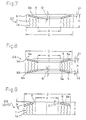
- Fig. 16 is a longitudinal section view of a gland packing of a seventeenth embodiment of the invention.
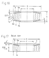
- Fig. 17 is a longitudinal section view another example of a gland packing G18 corresponding to the gland packing known from DE-A-39 04 200.
- Fig. 18 is a longitudinal section view showing use example 1 of the gland packings of the embodiments of the invention.
- Fig. 19 is a longitudinal section view showing use example 2 of the gland packings of the embodiments of the invention.
- Fig. 21 is an enlarged half longitudinal section view illustrating the penetration leakage prevention action in a use state of the gland packing of the second embodiment of the invention.
- Fig. 22 is an enlarged half longitudinal section view illustrating the deformation action of a projected part in a use state of the gland packing of the first embodiment of the invention.
- Fig. 23 is a table in which stress generating states of the packings of the invention, a prior art packing, and comparison packings are listed.
- Fig. 24 is a table showing results of gas-seal tests of use examples 1 to 5 of the gland packing of the invention, and use examples of prior art packings.
- Fig. 25 is a half longitudinal section view showing an example of a prior art gland packing.
- Fig. 26 is a longitudinal section view showing a use example of the prior art gland packing.
- Fig. 27 is a longitudinal section view showing another use example of the prior art gland packing.
- Fig. 28 is a half longitudinal section view showing another example of a prior art gland packing.
- Fig. 29 is a longitudinal section view showing a use example of the gland packing of Fig. 28.
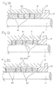
- Fig. 30 is a half longitudinal section view showing an example of a gland packing which is a comparison example.
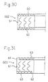
- Fig. 31 is a half longitudinal section view showing another example of a gland packing which is a comparison example.
- Fig. 1 is a longitudinal section view of a gland packing G1 of a first embodiment of the invention.
- 1 designates a die mold packing part.
- the die mold packing part 1 is configured by windingly laminating an expanded graphite tape 1a into a spiral shape, and die-molding the lamination into a ring-like shape having dimensions of an inner diameter d of 32 mm, an outer diameter D of 48 mm, and a height h of 12 mm.
- the ring-like seal members 4 and 5 designate ring-like seal members which are respectively brought into tight contact with the end faces in the axial direction of the die mold packing part 1 excluding the outer and inner ring-like projected parts 2 and 3.
- the ring-like seal members 4 and 5 are formed by laminating three punched products of an expanded graphite sheet (thickness of 0.38 mm) having impermeability, and the laminated product is compressed together with the die mold packing part 1. As a result, the section shape shown in Fig. 1 is formed.
- the expanded graphite tape 1a constituting the die mold packing part 1 a product obtained by compounding (laminating) knitted meshes of a thin metal wire, or metal foil may be used.
- the ring-like seal members 4 and 5 may adhere to the die mold packing part 1 so as to be integrated therewith. However, the adhesion of the members is not necessary because the positioning of the members is conducted by the existence of the projected parts 2 and 3.
- Fig. 2 is a longitudinal section view of a gland packing G2 of a second embodiment of the invention.
- a ring-like projected part 2 is projected outward in an axial direction from one end face in the axial direction of a die mold packing part 1 and in the outer end portion in a radial direction, so as to be integrally formed, and a ring-like seal member 4 is brought into tight contact with only one end face in the axial direction of the die mold packing part 1 excluding the ring-like projected part 2.
- the method of forming the section shape shown in the figure, the configuration of the die mold packing part 1 and the ring-like seal member 4, the dimensions (d, D, h, ⁇ 1) of the parts, etc. are the same as those of the first embodiment, and hence their detailed description is omitted.
- Fig. 3 is a longitudinal section view of a gland packing G3 of a third embodiment of the invention.
- ring-like projected parts 2A and 2B are projected outward in an axial direction from the both end faces in the axial direction of a die mold packing part 1 and in the outer end portion in a radial direction, so as to be integrally formed, and ring-like seal members 4 and 5 are respectively brought into tight contact with the both end faces in the axial direction of the die mold packing part 1 excluding the ring-like projected parts 2A and 2B.
- Fig. 4 is a longitudinal section view of a gland packing G4 of a fourth embodiment of the invention.
- a ring-like projected part 3 is projected outward in an axial direction from one end face in the axial direction of the die mold packing part 1 and in the inner end portion in a radial direction, so as to be integrally formed, and a ring-like seal member 4 is brought into tight contact with only one end face in the axial direction of the die mold packing part 1 excluding the ring-like projected part 3.
- the method of forming the section shape shown in the figure, the configuration of the die mold packing part 1 and the ring-like seal member 4, the dimensions (d, D, h, ⁇ 1) of the parts, etc. are the same as those of the first embodiment, and hence their detailed description is omitted.
- Fig. 5 is a longitudinal section view of a gland packing G5 of a fifth embodiment of the invention.
- ring-like projected parts 3A and 3B are projected outward in an axial direction from the both end faces in the axial direction of a die mold packing part 1 and in the inner end portion in a radial direction, so as to be integrally formed, and ring-like seal members 4 and 5 are respectively brought into tight contact with the both end faces in the axial direction of the die mold packing part 1 excluding the ring-like projected parts 3A and 3B.
- the method of forming the section shape shown in the figure, the configuration of the die mold packing part 1, the dimensions (d, D, h, ⁇ 1, ⁇ 2) of the parts, etc. are the same as those of the first embodiment except that punched stainless steel plates of a thickness of 0.2 mm are used as the ring-like seal members 4 and 5, and hence their detailed description is omitted.
- Fig. 6 is a longitudinal section view of a gland packing G6 of a sixth embodiment of the invention.
- 1 designates a die mold packing part.
- the die mold packing part 1 is configured by windingly laminating an expanded graphite tape 1a into a spiral shape, and die-molding the lamination into a ring-like shape having dimensions of an inner diameter d of 32 mm, an outer diameter D of 48 mm, and a height h of 10 mm.
- the ring-like seal members 8 and 9 designate ring-like seal members which are respectively brought into tight contact with the end faces in the axial direction of the die mold packing part 1 excluding the outer and inner ring-like projected parts 6 and 7.
- the ring-like seal members 8 and 9 are configured by punched stainless steel plates of a thickness of 0.2 mm so that outer faces 8a and 9a of the members are respectively formed as oblique circular cone faces which have an inclination ⁇ of 15° to a plane perpendicular to the axis so as to be positioned more outward in the axial direction as moving toward the ring-like projected parts 6 and 7, and the projection end faces 6a and 7a of the ring-like projected parts 6 and 7 are respectively substantially positioned in extension planes of the oblique circular cone faces 8a and 9a.
- Fig. 7 is a longitudinal section view of a gland packing G7 of a seventh embodiment of the invention.
- a ring-like projected part 6 is projected outward in an axial direction from one end face in the axial direction of a die mold packing part 1 and in the outer end portion in a radial direction, so as to be integrally formed, and a ring-like seal member 8 is brought into tight contact with only one end face in the axial direction of the die mold packing part 1 excluding the ring-like projected part 6.
- the outer face 8a of the ring-like seal member 8 is formed as an oblique circular cone face which is positioned more outward in an axial direction as moving toward the ring-like projected part 6.
- the ring-like seal member 8 is formed by laminating three punched products of an expanded graphite sheet (thickness of 0.38 mm) having impermeability, and the laminated product is compressed together with the die mold packing part 1. As a result, the section shape shown in Fig. 7 is formed.
- the configuration of the die mold packing part 1 other than the above, the dimensions (d, D, h, ⁇ 1, ⁇ ) of the parts, etc. are the same as those of the sixth embodiment, and hence their detailed description is omitted.
- Fig. 8 is a longitudinal section view of a gland packing G8 of an eighth embodiment of the invention.
- ring-like projected parts 6A and 6B are projected outward in an axial direction from the both end faces in the axial direction of a die mold packing part 1 and in the outer end portion in a radial direction, so as to be integrally formed, and ring-like seal members 8 and 9 are respectively brought into tight contact with the both end faces in the axial direction of the die mold packing part 1 excluding the ring-like projected parts 6A and 6B.
- Outer faces 8a and 9a of the ring-like seal members 8 and 9 are respectively formed as oblique circular cone faces which are positioned more outward in an axial direction as moving toward the ring-like projected parts 6A and 6B.
- the ring-like seal members 8 and 9 are configured by using a punched polytetrafluoroetylene (PTFE) resin sheet of a thickness of 1.0 mm, and the sheet is compressed together with the die mold packing part 1. As a result, the section shape shown in Fig. 8 is formed.
- the configuration of the die mold packing part 1 other than the above, the dimensions (d, D, h, ⁇ 1, ⁇ 2, ⁇ ) of the parts, etc. are the same as those of the sixth embodiment, and hence their detailed description is omitted.
- Fig. 9 is a longitudinal section view of a gland packing G9 of a ninth embodiment of the invention.
- a ring-like projected part 7 is projected outward in an axial direction from one end face in the axial direction of a die mold packing part 1 and in the inner end portion in a radial direction, so as to be integrally formed, and a ring-like seal member 8 is brought into tight contact with only one end face in the axial direction of the die mold packing part 1 excluding the ring-like projected part 7.
- the outer face 8a of the ring-like seal member 8 is formed as an oblique circular cone face which is positioned more outward in an axial direction as moving toward the ring-like projected part 7.
- the ring-like seal member 8 is formed by laminating three punched products of an expanded graphite sheet (thickness of 0.38 mm) having impermeability, and the laminated product is compressed together with the die mold packing part 1. As a result, the section shape shown in Fig. 7 is formed.
- the configuration of the die mold packing part 1 other the above, the dimensions (d, D, h, ⁇ 1, ⁇ ) of the parts, etc. are the same as those of the sixth embodiment, and hence their detailed description is omitted.
- a gland packing G10 (see Fig. 9) of a tenth embodiment is strictly the same as the ninth embodiment except that PTFE-impregnated glass fiber fabric is used as the ring-like seal member 8, and hence its illustration and detailed description are omitted.
- Fig. 10 is a longitudinal section view of a gland packing G11 of an eleventh embodiment of the invention.
- a ring-like projected part 6 which is projected outward in an axial direction from one end face in the axial direction of a die mold packing part 1 and in the outer end portion in a radial direction and integrally formed
- a ring-like projected part 7 which is projected outward in an axial direction (opposite to the ring-like projected part 6) from the other end face in the axial direction of the die mold packing part 1 and in the inner end portion in a radial direction and integrally formed
- the projection end face 6a of the ring-like projected part 6 which is outside in a radial direction is projected outward in the axial direction beyond an oblique circular cone face 8a of one seal member 8 of ring-like seal members 8 and 9 which are brought into tight contact with the both end faces in the axial direction of the die mold packing part 1 so as to be formed as oblique circular cone faces which have an inclination
- Fig. 11 is a longitudinal section view of a gland packing G12 of a twelfth embodiment of the invention.
- the projection end face 6a of a ring-like projected part 6 which is projected outward in an axial direction from one end face in the axial direction of a die mold packing part 1 and in the outer end portion in a radial direction is projected outward in the axial direction beyond an oblique circular cone face 8a of a ring-like seal member 8 which is brought into tight contact on the side of the one end face in the axial direction of the die mold packing part 1 so that the outer face 8a is formed as an oblique circular cone face which is positioned more outward in an axial direction as moving toward the ring-like projected part 6.
- the method of forming the section shape shown in the figure, the other configuration, the dimensions of the parts, etc. are the same as those of the seventh embodiment, and hence their detailed description is omitted.
- Fig. 12 is a longitudinal section view of a gland packing G13 of a thirteenth embodiment of the invention.
- the projection end faces 6a and 6b of ring-like projected parts 6A and 6B which are respectively projected outward in an axial direction from the both end faces in the axial direction of a die mold packing part 1 and in the outer end portions in a radial direction are projected outward in an axial direction beyond oblique circular cone faces 8a and 9a of the ring-like seal members 8 and 9 which are brought into tight contact with the both end faces in the axial direction of the die mold packing part 1 so that the outer faces 8a and 9a are formed as oblique circular cone faces which are respectively positioned more outward in an axial direction as moving toward the ring-like projected parts 6A and 6B.
- the method of forming the section shape shown in the figure, the other configuration, the dimensions of the parts, etc. are the same as those of the eighth embodiment, and hence their detailed description is omitted.
- Fig. 14 is a longitudinal section view of a gland packing G15 of a fifteenth embodiment of the invention.
- the embodiment is configured so that the outer faces 8a and 9a of the ring-like projected parts 8 and 9 which are respectively brought into tight contact with the both end faces in the axial direction of a die mold packing part 1 are respectively formed as oblique circular cone faces which have an inclination ⁇ of 15° to a plane perpendicular to the axis so as to be positioned more inward in an axial direction as moving toward the ring-like projected parts 6 and 7, in the opposite manner as the sixth embodiment, and the projection end faces 6a and 7a of the ring-like projected parts 6 and 7 are respectively substantially positioned in extension planes of the oblique circular cone faces 8a and 9a.
- the method of forming the section shape shown in the figure, the other configuration, the dimensions of the parts, etc. are the same as those of the sixth embodiment, and hence their detailed description is omitted.
- Fig. 16 is a longitudinal section view of a gland packing G17 of a sixteenth embodiment of the invention.
- ring-like seal members 8 and 9 which are respectively brought into tight contact with the both end faces in an axial direction of a die mold packing part 1 are formed so that the outer faces 8a and 9a are formed as oblique circular cone faces which are positioned more inward in an axial direction as moving toward ring-like projected parts 6A and 6B in the opposite manner as the eighth embodiment.
- the method of forming the section shape shown in the figure, the other configuration, the dimensions of the parts, etc. are the same as those of the eighth embodiment, and hence their detailed description is omitted.
- the expanded graphite tape la constituting the die mold packing part 1 a product obtained by compounding (laminating) knitted meshes of a thin metal wire, or metal foil may be used.
- the ring-like seal members 4, 5, 8, and 9, any sheet having impermeability may be used.
- the material of the members may be adequately selected from an expanded graphite sheet; a stainless steel plate; and a PTFE sheet; and in addition a film of polyphenylene sulfide (PPS), polyether ether ketone (PEEK), aramid, or the like; a sheet of nitrile-butadiene rubber (NBR), chloroprene rubber (CR), synthetic rubber (SR), fluoro rubber, or the like; and a metal foil or a thin plate of copper, aluminum, lead, inconel, or the like.
- PPS polyphenylene sulfide
- PEEK polyether ether ketone
- aramid or the like
- NBR nitrile-butadiene rubber
- CR chloroprene rubber
- SR synthetic rubber
- the ring-like seal members 4, 5, 8, and 9 may adhere to the die mold packing part 1 so as to be integrated therewith. However, the adhesion of the members is not necessary because the positioning of the members is conducted by the existence of the projected parts 2, 3, 6, and 7.
- Fig. 18 shows a use manner in which a plurality of gland packings G2 of the second embodiment and gland packings G4 of the fourth embodiment are alternately arranged in an axial direction on the outer peripheral face of a valve rod or the like 11 in a stuffing box 10, braided packings 12 and 12 are respectively disposed at the both ends in the axial direction of the arrangement, and a tightening force is applied to one end in the axial direction through a packing gland 13, thereby forming a shaft seal part.
- minute gaps 14 such as shown in Fig. 21 are formed in windingly laminated parts of the expanded graphite tape 1a constituting the die mold packing part 1 of each of the gland packings G2 and G4, and a pressurized fluid penetrates into the minute gaps 14.
- the leakage of the penetrating fluid to the outside is blocked by the ring-like seal member 4 and also stress relaxation due to the swelling out in the axial direction of the die mold packing part 1 is suppressed by the ring-like seal member 4.
- the ring-like projected part 2 which is projected outward in the axial direction from the die mold packing part 1 is easily deformed by applying a low tightening force in the axial direction, and hence the density of the projected part is increased and a large stress is generated in a radial direction so that the packing is strongly brought into tight contact with the inner face of the stuffing box 10 and the outer peripheral face of the valve rod or the like 11.
- the ring-like projected part 2 has a closely packed folded structure and is very elastic, and hence can satisfactorily follow a small amount of wear, thereby ensuring penetration leak prevention and high sealing properties.
- Fig. 19 shows a use manner in which a plurality of gland packings G1 of the first embodiment and gland packings 51 of the prior art shown in Fig. 25 are alternately arranged in an axial direction on the outer peripheral face of a valve rod or the like 11 in a stuffing box 10, and a tightening force is applied to one end in the axial direction through a packing gland 13, thereby forming a shaft seal part.
- a pressurized fluid penetrates into the minute gaps 59 such as shown in Fig.
- the ring-like projected parts 2 and 3 which are projected outward in the axial direction from the die mold packing part 1 are easily deformed as shown in Fig. 22 by applying a low tightening force in the axial direction, and hence the density of the projected part is increased and a large stress is generated in a radial direction so that the packing is strongly brought into tight contact with the inner face of the stuffing box 10 and the outer peripheral face of the valve rod or the like 11.
- this surely prevents also the leakage through the projected parts 2 and 3 from occurring, and enhances sealing properties between the stuffing box 10 and the valve rod or the like 11.
- the ring-like projected parts 2 and 3 have a closely packed folded structure and are very elastic, and hence can satisfactorily follow a small amount of wear, thereby ensuring penetration leak prevention and high sealing properties.
- Fig. 20 shows a use manner in which a plurality of gland packings G7 of embodiment 7 and gland packings G9 or G10 of embodiment 9 or 10 are alternately arranged in an axial direction on the outer peripheral face of a valve rod or the like 11 in a stuffing box 10, and a tightening force is applied to one end in the axial direction through a packing gland 13, thereby forming a shaft seal part.
- the ring-like seal member 8 blocks the leakage of the fluid penetrating into the minute gaps 14 to the outside, and suppresses stress relaxation due to the swelling out in the axial direction of the die mold packing part 1.
- the ring-like projected parts 6A and 6B and the ring-like seal member 8 are easily deformed by applying a low tightening force in the axial direction so as to be positioned in a plane substantially perpendicular to the axis of the valve rod or the like 11, and hence the density of the projected parts 6A and 6B is increased and a large stress is generated in a radial direction so that the projected parts are strongly brought into tight contact with the inner face of the stuffing box 10 and the outer peripheral face of the valve rod or the like 11. This can surely prevent penetration leakage through the projected parts 6A and 6B from occurring, and maintain sealing properties between the stuffing box 10 and the valve rod or the like 11 at a high level.
- the gland packing G12 of embodiment 12 and the gland packing G14 of embodiment 14 are similarly used so as to form a shaft seal part. Also in the use manner, in the same manner as that described in use example 3, penetration leak prevention and high sealing properties between the stuffing box 10 and the valve rod or the like 11 can be maintained.
- gland packings G7 and G9 or G10 used in use example 3 shown in Fig. 20 the gland packings G16 and G18 known from DE-A-39 04 200 are similarly used so as to form a shaft seal part. Also in the use manner, in the same manner as that described in use examples 3 and 4, penetration leak prevention and high sealing properties between the stuffing box 10 and the valve rod or the like 11 can be maintained.
- Fig. 23 is a table showing stress generating states in the case where the gland packing G1 of the first embodiment and the gland packing G6 of the sixth embodiment are used as the gland packing of the invention, a gland packing G01 consisting only of the die mold packing 51 shown in Fig. 25 is used as a prior art packing, gland packings G02 and G03 are used as comparison packings, the gland packing G02 being formed by bringing ring-like seal members 60 and 60 into tight contact with the whole area of the both end faces in the axial direction of the die mold packing 51 as shown in Fig.
- the gland packing G03 being formed by integrally projecting ring-like projected parts 61 and 62 from the both end faces in the axial direction of the die mold packing 51 and in the outer and inner end portions in a radial direction, and bringing ring-like seal members 63 and 63 of a thickness corresponding to the same height as that of the projected parts 61 and 62 into tight contact with the both end faces in the axial direction of the die mold packing 51 excluding the projected parts 61 and 62, and a constant compression force f is applied in the axial direction to the gland packings.
- the length of each arrow corresponds to the magnitude of the stress.
- the stresses of the portions corresponding to the ring-like projected parts 2 and 3, and 6 and 7 are very greater than those in the prior art packing and the comparison packings, the performance of preventing a fluid from leaking through the ring-like projected parts 2 and 3, and 6 and 7 is excellent, and the tight adhesion force against the stuffing box and the outer peripheral face of a valve rod or the like is large so as to exhibit excellent sealing properties.
- Fig. 24 is a table showing results of gas-seal tests which were conducted on use examples 1 to 5 of the gland packing of the invention, and the use examples of prior art packings shown in Figs. 26, 27 and 29 under the conditions that nitrogen gas N2 was filled at 21 Kgf/cm2 at ordinary temperature.
- the leakage amount is very small even in the case where the tightening face pressure is low, thereby exhibiting excellent sealing properties.
- the leakage amount can be improved to a level of 1/10 to 1/100.
- the projected part which is formed on the die mold packing part so as to be outward projected in the axial direction can be easily deformed only by applying a low tightening force in the axial direction, and hence the density of the projected part is increased and a large stress is generated in a radial direction so that the packing is strongly brought into tight contact with the inner face of the stuffing box and the outer peripheral face of a valve rod or the like. This surely prevents penetration leakage through the projected part from occurring, and the sealing properties between the stuffing box and the valve rod can be maintained at a high level.
- the ring-like projected part has a closely packed folded structure and is very elastic, and hence the ring-like projected part can satisfactorily follow a small amount of wear, thereby attaining an effect that the penetration leak prevention and high sealing properties can be maintained for a long term.
- the ring-like projected part which is formed on the die mold packing part so as to be outward projected in an axial direction, and the ring-like seal member are easily deformed only by applying a low tightening force in the axial direction, so that the projected part and the seal member are positioned in a plane substantially perpendicular to the axis of the valve rod or the like, and hence the density of the projected part is increased and a large stress is generated in a radial direction so that the projected part and the seal member are strongly brought into tight contact with the inner face of the stuffing box and the outer peripheral face of the valve rod or the like.
- the penetration leak prevention and high sealing properties can be maintained for a long term.
- a ring-like projected part and ring-like seal member are strongly brought into tight contact with the inner face of a stuffing box and the outer peripheral face of a valve rod or the like, only by applying a low tightening force in an axial direction, whereby the penetration leak prevention and high sealing properties can be ensured maintained for a long term.
Landscapes
- Engineering & Computer Science (AREA)
- General Engineering & Computer Science (AREA)
- Mechanical Engineering (AREA)
- Sealing Devices (AREA)
Claims (9)
- Garniture de presse-étoupe, dans laquelle une partie saillante semblable à un anneau (2, 3, 2A, 2B, 3A, 3B) qui. fait saillie vers l'extérieur dans une direction axiale est formée sur au moins une face d'extrémité dans une direction axiale d'une partie de garniture moulée en matrice (1) et dans au moins l'une des parties d'extrémités extérieure et intérieure dans une direction radiale, ladite partie de garniture moulée en matrice (1) étant configurée en stratifiant de façon enroulée un ruban de graphite expansé (la) suivant une forme en spirale et en moulant en matrice la stratification suivant une forme semblable à un anneau, un élément d'étanchéité semblable à un anneau (4, 5) est amené jusqu'en contact serré avec ladite face d'extrémité dans la direction axiale de ladite partie de garniture moulée en matrice (1) en excluant ladite partie saillante semblable à un anneau (2, 3, 2A, 2B, 3A, 3B), et ladite partie saillante semblable à un anneau (2, 3, 2A, 2B, 3A, 3B) fait saillie dans la direction axiale au-delà d'une face extérieure dudit élément d'étanchéité semblable à un anneau (4, 5).
- Garniture de presse-étoupe selon la revendication 1, dans laquelle les parties saillantes semblables à des anneaux (2, 3, 2A, 2B, 3A, 3B) font saillie respectivement vers l'extérieur dans la direction axiale depuis les deux faces d'extrémités dans la direction axiale de ladite partie de garniture moulée en matrice (1) et dans la partie d'extrémité extérieure ou intérieure dans une direction radiale, et les éléments d'étanchéité semblables à des anneaux (4, 5) sont respectivement amenés jusqu'en contact serré avec lesdites faces d'extrémités dans la direction axiale de ladite partie de garniture moulée en matrice (1) en excluant lesdites parties saillantes semblables à des anneaux (2, 3, 2A, 2B, 3A, 3B),
- Garniture de presse-étoupe selon la revendication 1, dans laquelle les parties saillantes semblables à des anneaux (2, 3) font saillie respectivement vers l'extérieur dans la direction axiale depuis une face d'extrémité dans la direction axiale de ladite partie de garniture moulée en matrice (1) et dans la partie d'extrémité intérieure dans une direction radiale, et l'autre face d'extrémité dans la direction axiale de ladite partie de garniture moulée en matrice (1) et dans la partie d'extrémité extérieure dans une direction radiale, et les éléments d'étanchéité semblables à des anneaux (4) sont respectivement amenés jusqu'en contact serré avec lesdites faces d'extrémités dans la direction axiale de ladite partie de garniture moulée en matrice (1) en excluant lesdites parties saillantes semblables à des anneaux (2, 3).
- Garniture de presse-étoupe, dans laquelle une partie saillante semblable à un anneau (6, 7, 6A, 6B) qui fait saillie vers l'extérieur dans une direction axiale est formée sur au moins une face d'extrémité dans une direction axiale d'une partie de garniture moulée en matrice (1) et dans au moins l'une des parties d'extrémités extérieure et intérieure dans une direction radiale, ladite partie de garniture moulée en matrice (1) étant configurée en stratifiant de façon enroulée un ruban de graphite expansé (la) suivant une forme en spirale et en moulant en matrice la stratification suivant une forme semblable à un anneau, un élément d'étanchéité semblable à un anneau (8, 9) est amené jusqu'en contact serré avec ladite une face d'extrémité dans la direction axiale de ladite partie de garniture moulée en matrice en excluant ladite partie saillante semblable à un anneau, la face extérieure dudit élément d'étanchéité semblable à un anneau est réalisée sous forme d'une face conique circulaire oblique (8a, 9a) qui est positionnée plus vers l'extérieur dans la direction axiale lorsqu'on se déplace en direction de ladite partie saillante semblable à un anneau, et la face d'extrémité de saillie (6a, 7a, 6b) de ladite partie saillante semblable à un anneau (6, 7, 6A, 6B) est positionnée pratiquement dans un plan en prolongement de ladite face conique circulaire oblique (8a, 9a).
- Garniture de presse-étoupe selon la revendication 4, dans laquelle les parties saillantes semblables à des anneaux (6, 7, 6A, 6B) font saillie respectivement vers l'extérieur dans la direction axiale depuis les deux faces d'extrémités dans la direction axiale de ladite partie de garniture moulée en matrice (1) et dans la partie d'extrémité extérieure ou intérieure dans une direction radiale, et les éléments d'étanchéité semblables à des anneaux (8, 9) sont amenés respectivement jusqu'en contact serré avec lesdites faces d'extrémités dans la direction axiale de ladite partie de garniture moulée en matrice (1) en excluant lesdites parties saillantes semblables à des anneaux (6, 7, 6A, 6B).
- Garniture de presse-étoupe selon la revendication 4, dans laquelle des parties saillantes semblables à des anneaux (6, 7) font saillie respectivement vers l'extérieur dans la direction axiale depuis une face d'extrémité dans la direction axiale de ladite partie de garniture moulée en matrice (1) et dans la partie d'extrémité intérieure dans une direction radiale, et également depuis l'autre face d'extrémité dans la direction axiale de ladite partie de garniture moulée en matrice (1) et dans la partie d'extrémité extérieure dans une direction radiale, et les éléments d'étanchéité semblables à des anneaux (8) sont amenés respectivement jusqu'en contact serré avec lesdites faces d'extrémités dans la direction axiale de ladite partie de garniture moulée en matrice (1) en excluant lesdites parties saillantes semblables à des anneaux (6, 7).
- Garniture de presse-étoupe, dans laquelle une partie saillante semblable à un anneau (6, 7, 6A, 6B) qui fait saillie vers l'extérieur dans une direction axiale est formée sur au moins une face d'extrémité dans une direction axiale d'une partie de garniture moulée en matrice (1) et dans au moins l'une des parties d'extrémités extérieure et intérieure dans une direction radiale, ladite partie de garniture moulée en matrice (1) étant configurée en stratifiant de façon enroulée un ruban de graphite expansé (la) suivant une forme en spirale et en moulant en matrice la stratification suivant une forme semblable à un anneau, un élément d'étanchéité semblable à un anneau (8, 9) est amené jusqu'en contact serré avec ladite une face d'extrémité dans la direction axiale de ladite partie de garniture moulée en matrice (1) en excluant ladite partie saillante semblable à un anneau (8, 9), la face extérieure dudit élément d'étanchéité semblable à un anneau (8, 9) est réalisée sous forme d'une face conique circulaire oblique (8a, 9a) qui est positionnée plus vers l'intérieur dans la direction axiale lorsqu'on se déplace en direction de ladite partie saillante semblable à un anneau (8, 9), et la face d'extrémité de saillie de ladite partie saillante semblable à un anneau est positionnée pratiquement dans un plan en prolongement de ladite face conique oblique, et dans laquelle lesdites parties saillantes semblables à des anneaux (6, 7, 6A, 6B) font respectivement saillie vers l'extérieur dans la direction axiale depuis les deux faces d'extrémités dans la direction axiale de ladite partie de garniture moulée en matrice (1) et dans la partie d'extrémité extérieure ou intérieure dans une direction radiale, et lesdits éléments d'étanchéité semblables à des anneaux (8, 9) sont amenés respectivement jusqu'en contact serré avec lesdites faces d'extrémités dans la direction axiale de ladite partie de garniture moulée en matrice (1) en excluant lesdites parties saillantes semblables à des anneaux (6, 7, 6A, 6B).
- Garniture de presse-étoupe, dans laquelle une partie saillante semblable à un anneau (6, 7) qui fait saillie vers l'extérieur dans une direction axiale est formée sur au moins une face d'extrémité dans une direction axiale d'une partie de garniture moulée en matrice (1) et dans au moins l'une des parties d'extrémités extérieure et intérieure dans une direction radiale, ladite partie de garniture moulée en matrice (1) étant configurée en stratifiant de façon enroulée un ruban de graphite expansé (1a) suivant une forme en spirale et en moulant en matrice la stratification suivant une forme semblable à un anneau, un élément d'étanchéité semblable à un anneau (8) est amené jusqu'en contact serré avec ladite une face d'extrémité dans la direction axiale de ladite partie de garniture moulée en matrice (1) en excluant ladite partie saillante semblable à un anneau (6, 7), la face extérieure dudit élément d'étanchéité semblable à un anneau (8) est réalisée sous forme d'une face conique circulaire oblique (8a) qui est positionnée plus vers l'intérieur dans la direction axiale lorsqu'on se déplace en direction de ladite partie saillante semblable à un anneau (6, 7), et la face d'extrémité de saillie de ladite partie saillante semblable à un anneau (6, 7) est positionnée pratiquement dans un plan en prolongement de ladite face conique circulaire oblique (8a), et dans laquelle lesdites parties saillantes semblables à des anneaux (6, 7) font saillie respectivement vers l'extérieur dans la direction axiale depuis une face d'extrémité dans la direction axiale de ladite partie de garniture moulée en matrice (1), et dans la partie d'extrémité intérieure dans une direction radiale, et également depuis l'autre face d'extrémité dans la direction axiale de ladite partie de garniture moulée en matrice (1) et dans la partie d'extrémité extérieure dans une direction radiale, et lesdits éléments d'étanchéité semblables à des anneaux sont amenés respectivement jusqu'en contact serré avec lesdites faces d'extrémités dans la direction axiale de ladite partie de garniture moulée en matrice (1) en excluant lesdites parties saillantes semblables à des anneaux (6, 7).
- Garniture de presse-étoupe selon l'une quelconque des revendications 1, 2, 3, 4, 5, 6, 7 et 8, dans laquelle ledit élément d'étanchéité semblable à un anneau (4, 5, 8, 9) est choisi à partir d'une stratification d'un matériau en feuille présentant une imperméabilité, une simple plaque et une feuille métallique.
Applications Claiming Priority (4)
| Application Number | Priority Date | Filing Date | Title |
|---|---|---|---|
| JP9493094 | 1994-05-09 | ||
| JP6094930A JP2594231B2 (ja) | 1994-05-09 | 1994-05-09 | グランドパッキン |
| JP94930/94 | 1994-05-09 | ||
| PCT/JP1995/000862 WO1995030851A1 (fr) | 1994-05-09 | 1995-05-01 | Garniture d'etancheite |
Publications (3)
| Publication Number | Publication Date |
|---|---|
| EP0708280A1 EP0708280A1 (fr) | 1996-04-24 |
| EP0708280A4 EP0708280A4 (fr) | 1996-06-12 |
| EP0708280B1 true EP0708280B1 (fr) | 2001-08-29 |
Family
ID=14123692
Family Applications (1)
| Application Number | Title | Priority Date | Filing Date |
|---|---|---|---|
| EP95917500A Expired - Lifetime EP0708280B1 (fr) | 1994-05-09 | 1995-05-01 | Garniture d'etancheite |
Country Status (8)
| Country | Link |
|---|---|
| US (3) | US5803464A (fr) |
| EP (1) | EP0708280B1 (fr) |
| JP (1) | JP2594231B2 (fr) |
| KR (1) | KR100190439B1 (fr) |
| CN (1) | CN1039254C (fr) |
| DE (1) | DE69522403T2 (fr) |
| TW (1) | TW298278U (fr) |
| WO (1) | WO1995030851A1 (fr) |
Families Citing this family (18)
| Publication number | Priority date | Publication date | Assignee | Title |
|---|---|---|---|---|
| US6273431B1 (en) * | 1999-11-15 | 2001-08-14 | Garlock Inc | Forged valve stem packing set |
| DE60315478T2 (de) * | 2002-09-11 | 2008-04-24 | Nippon Pillar Packing Co., Ltd. | Material für stopfbuchse und stopfbuchse |
| US7021632B2 (en) * | 2004-03-04 | 2006-04-04 | Flowserve Management Company | Self-energized gasket and manufacturing method therefor |
| US7878744B2 (en) * | 2006-06-06 | 2011-02-01 | Nd Industries, Inc. | Fibrous microencapsulated washer for fasteners |
| US20070296161A1 (en) * | 2006-06-21 | 2007-12-27 | Dudman Richard L | Seal, Sealing System, and Method for Sealing |
| SG2012071635A (en) * | 2009-03-27 | 2014-04-28 | Cameron Int Corp | Full bore compression sealing method |
| CA2758465A1 (fr) * | 2009-04-17 | 2010-10-21 | Garlock Sealing Technologies Llc | Distributeur de garniture de tige |
| JP5834806B2 (ja) | 2011-11-17 | 2015-12-24 | オイレス工業株式会社 | 円筒状ガスケット及びその製造方法並びに該円筒状ガスケットを使用した差し込み型排気管継手 |
| DE102011055740A1 (de) * | 2011-11-25 | 2013-05-29 | Kempchen Dichtungstechnik Gmbh | Dichtpackungsring sowie Dichtpackungssatz mit einer Vielzahl von Dichtpackungsringen |
| US8814432B2 (en) * | 2012-03-23 | 2014-08-26 | Seal-Ryt Corporation | Seal-bearing assembly |
| JP5972208B2 (ja) * | 2013-04-05 | 2016-08-17 | 日本ピラー工業株式会社 | グランドパッキン |
| US20140356523A1 (en) * | 2013-05-29 | 2014-12-04 | GM Global Technology Operations LLC | Materials, methods, and apparatus for improving leak robustness |
| JP6595583B2 (ja) * | 2015-04-10 | 2019-10-23 | 日本ピラー工業株式会社 | グランドパッキン、及びグランドパッキンの製造方法 |
| CN107407419B (zh) * | 2015-04-10 | 2020-08-25 | 日本皮拉工业株式会社 | 压盖密封和压盖密封的制造方法 |
| CN107532729B (zh) * | 2015-05-13 | 2019-11-22 | 株式会社开滋 | 固定型球阀以及阀的密封构造和阀用填料 |
| JP7093290B2 (ja) * | 2018-11-15 | 2022-06-29 | 日本ピラー工業株式会社 | グランドパッキン及びパッキン構造 |
| CN113833849A (zh) * | 2020-06-24 | 2021-12-24 | 中国石油化工股份有限公司 | 一种金刚石压腔高温高压实验用金属垫片及其制造方法 |
| CN114688250A (zh) * | 2022-04-19 | 2022-07-01 | 北京通美晶体技术股份有限公司 | 一种用于砷化镓晶体生长用新型密封结构 |
Family Cites Families (36)
| Publication number | Priority date | Publication date | Assignee | Title |
|---|---|---|---|---|
| US1381931A (en) * | 1919-04-05 | 1921-06-21 | Grapho Metal Packing Company | Yieldable packing |
| US1868199A (en) * | 1926-04-09 | 1932-07-19 | Pelterie Robert Esnault | Packing device |
| US1787020A (en) * | 1926-09-14 | 1930-12-30 | Linde Air Prod Co | Packing for rods and shafts |
| US1856051A (en) * | 1930-02-19 | 1932-04-26 | Flexitallic Gasket Co Inc | Gasket |
| US1924555A (en) * | 1931-09-18 | 1933-08-29 | Garlock Packing Co | Machinery packing |
| US1932809A (en) * | 1932-04-19 | 1933-10-31 | Harley T Wheeler | Helical accordion packing ring |
| US2357257A (en) * | 1942-12-28 | 1944-08-29 | Goetze Gasket & Packing Co Inc | Reinforced gasket |
| US2442311A (en) * | 1946-04-30 | 1948-05-25 | Flexitallic Gasket Co Inc | Composite compressible gasket |
| GB805253A (en) * | 1955-11-25 | 1958-12-03 | Trist & Co Ltd Ronald | Improvements relating to packing rings |
| US3179426A (en) * | 1962-06-25 | 1965-04-20 | Gen Motors Corp | High temperature actuator seal |
| US3132870A (en) * | 1962-12-14 | 1964-05-12 | Karl J Pschera | Gaskets and method of making same |
| JPS527738Y2 (fr) * | 1972-07-03 | 1977-02-18 | ||
| US4157835A (en) * | 1975-04-08 | 1979-06-12 | Otto Kahle | Strip seal for stuffing box packing |
| US4363465A (en) * | 1976-06-16 | 1982-12-14 | Smith International, Inc. | Extreme temperature, high pressure balanced, rising stem gate valve with super preloaded, stacked, solid lubricated, metal-to-metal seal |
| US4090719A (en) * | 1977-03-28 | 1978-05-23 | Vapor Corporation | Packing assembly |
| US4116451A (en) * | 1977-06-16 | 1978-09-26 | Maurer Engineering, Inc. | Shaft seal assembly and seal ring therefor |
| US4327923A (en) * | 1979-09-27 | 1982-05-04 | A. W. Chesterton Company | Packing |
| US4451047A (en) * | 1981-07-31 | 1984-05-29 | Smith International, Inc. | Seal |
| US4394023A (en) * | 1982-09-29 | 1983-07-19 | Daniel Industries Inc. | High temperature valve stem packing with coiled graphite seal rings |
| US4516785A (en) * | 1982-12-10 | 1985-05-14 | Chromium Corporation | Piston with a controlled expansion piston anti-extrusion ring |
| JPH0527738Y2 (fr) * | 1987-05-12 | 1993-07-15 | ||
| DE3745040C2 (de) * | 1987-07-03 | 1998-06-18 | Kempchen & Co Gmbh | Ventilspindeldichtung an Ventilspindeln von Hochdruckdampfventilen |
| DE3904200A1 (de) | 1989-02-13 | 1990-08-16 | Kempchen & Co Gmbh | Dichtungsanordnung, insbesondere hochdruck-dichtungsanordnung |
| JPH0715311B2 (ja) * | 1990-05-16 | 1995-02-22 | 日本ピラー工業株式会社 | リング状パッキンおよびその製造方法 |
| JPH073088Y2 (ja) * | 1990-08-06 | 1995-01-30 | 日本ピラー工業株式会社 | ブッシュ状パッキン |
| JP2769523B2 (ja) * | 1994-01-31 | 1998-06-25 | 株式会社キッツ | パッキンリングの構造とその製造方法並びにそれを用いたシール装置 |
| JPH0527738A (ja) * | 1991-07-24 | 1993-02-05 | Matsushita Electric Ind Co Ltd | データ変換テーブル切替装置 |
| US5201532A (en) * | 1991-12-12 | 1993-04-13 | Mark Controls Corporation | Flexible non-planar graphite sealing ring |
| JP3112118B2 (ja) * | 1992-05-18 | 2000-11-27 | 日本ピラー工業株式会社 | 自動車排気系用の渦巻形ガスケット |
| US5297805A (en) * | 1992-10-01 | 1994-03-29 | J.M. Clipper Corp. | Sealing ring |
| JPH086813B2 (ja) * | 1993-01-07 | 1996-01-29 | 日本ピラー工業株式会社 | リング状パッキン |
| CA2120315C (fr) * | 1993-04-30 | 2001-05-15 | Joel L. Williams | Articles medicaux et procede |
| US5499826A (en) * | 1993-06-18 | 1996-03-19 | Utex Industries, Inc. | Anti-extrusion lip seal |
| JP3359380B2 (ja) * | 1993-06-28 | 2002-12-24 | 北陽電機株式会社 | 光電スイッチ |
| US5687974A (en) * | 1996-03-15 | 1997-11-18 | Calconn, Inc. | Packing material having expanded graphite dispersed throughout |
| US5806858A (en) * | 1996-03-22 | 1998-09-15 | Garlock, Inc. | Compact five ring stuffing box packing assembly |
-
1994
- 1994-05-09 JP JP6094930A patent/JP2594231B2/ja not_active Expired - Fee Related
-
1995
- 1995-05-01 WO PCT/JP1995/000862 patent/WO1995030851A1/fr active IP Right Grant
- 1995-05-01 EP EP95917500A patent/EP0708280B1/fr not_active Expired - Lifetime
- 1995-05-01 CN CN95190398A patent/CN1039254C/zh not_active Expired - Fee Related
- 1995-05-01 DE DE69522403T patent/DE69522403T2/de not_active Expired - Lifetime
- 1995-05-01 US US08/549,783 patent/US5803464A/en not_active Expired - Lifetime
- 1995-05-01 KR KR1019950705796A patent/KR100190439B1/ko not_active IP Right Cessation
- 1995-05-03 TW TW084205943U patent/TW298278U/zh unknown
-
1998
- 1998-03-26 US US09/048,251 patent/US6082739A/en not_active Expired - Lifetime
-
2000
- 2000-06-13 US US09/592,761 patent/US8282106B1/en active Active
Also Published As
| Publication number | Publication date |
|---|---|
| US5803464A (en) | 1998-09-08 |
| KR100190439B1 (ko) | 1999-06-01 |
| EP0708280A1 (fr) | 1996-04-24 |
| CN1039254C (zh) | 1998-07-22 |
| DE69522403T2 (de) | 2002-06-20 |
| KR960703214A (ko) | 1996-06-19 |
| JP2594231B2 (ja) | 1997-03-26 |
| WO1995030851A1 (fr) | 1995-11-16 |
| CN1128558A (zh) | 1996-08-07 |
| US8282106B1 (en) | 2012-10-09 |
| DE69522403D1 (de) | 2001-10-04 |
| US6082739A (en) | 2000-07-04 |
| JPH07301338A (ja) | 1995-11-14 |
| EP0708280A4 (fr) | 1996-06-12 |
| TW298278U (en) | 1997-02-11 |
Similar Documents
| Publication | Publication Date | Title |
|---|---|---|
| EP0708280B1 (fr) | Garniture d'etancheite | |
| CA2125552C (fr) | Rondelles de garniture, mode de fabrication connexe et dispositif d'etancheite muni de ces rondelles | |
| US4449718A (en) | Packing for hydraulic pistons or piston rods | |
| EP0046774B1 (fr) | Enveloppe de presse-etoupe | |
| CA1052834A (fr) | Garniture composite | |
| EP0730713B1 (fr) | Unite de jointure etanche | |
| US7134671B2 (en) | Lip seal having increased contact force at interface and apparatus incorporating the same | |
| US4840379A (en) | Split sealing ring having a bias cut | |
| AU654046B2 (en) | Improvements in and relating to gaskets | |
| US9933071B2 (en) | Seal and method of manufacturing and/or using same | |
| US7055829B2 (en) | Antiextrusion device | |
| US3810639A (en) | Frangible backup ring for sealing rings | |
| KR20000064806A (ko) | 콤팩트5-링스터핑박스패킹조립체 | |
| US20070176373A1 (en) | Low stress / anti-buckling spiral wound gasket | |
| US3735991A (en) | Stuffing boxes | |
| JPH0811992B2 (ja) | フランジ継手構造 | |
| RU2149300C1 (ru) | Уплотнительное кольцо для вала насоса | |
| CN215980808U (zh) | 编织盘根 | |
| JP4058395B2 (ja) | パッキンとその製造方法 | |
| JPH0128370Y2 (fr) | ||
| JPH02212679A (ja) | ガス漏れシール | |
| Inoue | Metal gasket for cha. m casing engines | |
| JPH07122061B2 (ja) | 渦巻形ガスケット |
Legal Events
| Date | Code | Title | Description |
|---|---|---|---|
| PUAI | Public reference made under article 153(3) epc to a published international application that has entered the european phase |
Free format text: ORIGINAL CODE: 0009012 |
|
| 17P | Request for examination filed |
Effective date: 19951218 |
|
| AK | Designated contracting states |
Kind code of ref document: A1 Designated state(s): DE FR GB IT |
|
| A4 | Supplementary search report drawn up and despatched | ||
| AK | Designated contracting states |
Kind code of ref document: A4 Designated state(s): DE FR GB IT |
|
| 17Q | First examination report despatched |
Effective date: 19990224 |
|
| GRAG | Despatch of communication of intention to grant |
Free format text: ORIGINAL CODE: EPIDOS AGRA |
|
| GRAG | Despatch of communication of intention to grant |
Free format text: ORIGINAL CODE: EPIDOS AGRA |
|
| GRAH | Despatch of communication of intention to grant a patent |
Free format text: ORIGINAL CODE: EPIDOS IGRA |
|
| GRAH | Despatch of communication of intention to grant a patent |
Free format text: ORIGINAL CODE: EPIDOS IGRA |
|
| GRAA | (expected) grant |
Free format text: ORIGINAL CODE: 0009210 |
|
| AK | Designated contracting states |
Kind code of ref document: B1 Designated state(s): DE FR GB IT |
|
| ITF | It: translation for a ep patent filed |
Owner name: SOCIETA' ITALIANA BREVETTI S.P.A. |
|
| REF | Corresponds to: |
Ref document number: 69522403 Country of ref document: DE Date of ref document: 20011004 |
|
| REG | Reference to a national code |
Ref country code: GB Ref legal event code: IF02 |
|
| ET | Fr: translation filed | ||
| PLBE | No opposition filed within time limit |
Free format text: ORIGINAL CODE: 0009261 |
|
| STAA | Information on the status of an ep patent application or granted ep patent |
Free format text: STATUS: NO OPPOSITION FILED WITHIN TIME LIMIT |
|
| 26N | No opposition filed | ||
| PGFP | Annual fee paid to national office [announced via postgrant information from national office to epo] |
Ref country code: DE Payment date: 20130522 Year of fee payment: 19 Ref country code: GB Payment date: 20130521 Year of fee payment: 19 |
|
| PGFP | Annual fee paid to national office [announced via postgrant information from national office to epo] |
Ref country code: IT Payment date: 20130527 Year of fee payment: 19 Ref country code: FR Payment date: 20130603 Year of fee payment: 19 |
|
| REG | Reference to a national code |
Ref country code: DE Ref legal event code: R119 Ref document number: 69522403 Country of ref document: DE |
|
| GBPC | Gb: european patent ceased through non-payment of renewal fee |
Effective date: 20140501 |
|
| REG | Reference to a national code |
Ref country code: DE Ref legal event code: R119 Ref document number: 69522403 Country of ref document: DE Effective date: 20141202 |
|
| REG | Reference to a national code |
Ref country code: FR Ref legal event code: ST Effective date: 20150130 |
|
| PG25 | Lapsed in a contracting state [announced via postgrant information from national office to epo] |
Ref country code: DE Free format text: LAPSE BECAUSE OF NON-PAYMENT OF DUE FEES Effective date: 20141202 Ref country code: IT Free format text: LAPSE BECAUSE OF NON-PAYMENT OF DUE FEES Effective date: 20140501 |
|
| PG25 | Lapsed in a contracting state [announced via postgrant information from national office to epo] |
Ref country code: GB Free format text: LAPSE BECAUSE OF NON-PAYMENT OF DUE FEES Effective date: 20140501 Ref country code: FR Free format text: LAPSE BECAUSE OF NON-PAYMENT OF DUE FEES Effective date: 20140602 |