US1856051A - Gasket - Google Patents
Gasket Download PDFInfo
- Publication number
- US1856051A US1856051A US429530A US42953030A US1856051A US 1856051 A US1856051 A US 1856051A US 429530 A US429530 A US 429530A US 42953030 A US42953030 A US 42953030A US 1856051 A US1856051 A US 1856051A
- Authority
- US
- United States
- Prior art keywords
- gasket
- ring
- sheathing
- compressible
- corrugation
- Prior art date
- Legal status (The legal status is an assumption and is not a legal conclusion. Google has not performed a legal analysis and makes no representation as to the accuracy of the status listed.)
- Expired - Lifetime
Links
- 229910052751 metal Inorganic materials 0.000 description 12
- 239000002184 metal Substances 0.000 description 12
- 239000000463 material Substances 0.000 description 4
- 238000012856 packing Methods 0.000 description 4
- 230000001681 protective effect Effects 0.000 description 4
- 230000006835 compression Effects 0.000 description 2
- 238000007906 compression Methods 0.000 description 2
- 239000012530 fluid Substances 0.000 description 2
- RYGMFSIKBFXOCR-UHFFFAOYSA-N Copper Chemical compound [Cu] RYGMFSIKBFXOCR-UHFFFAOYSA-N 0.000 description 1
- 229910052782 aluminium Inorganic materials 0.000 description 1
- XAGFODPZIPBFFR-UHFFFAOYSA-N aluminium Chemical compound [Al] XAGFODPZIPBFFR-UHFFFAOYSA-N 0.000 description 1
- 239000010425 asbestos Substances 0.000 description 1
- 230000004888 barrier function Effects 0.000 description 1
- 230000015572 biosynthetic process Effects 0.000 description 1
- 238000010276 construction Methods 0.000 description 1
- 229910052802 copper Inorganic materials 0.000 description 1
- 239000010949 copper Substances 0.000 description 1
- 230000000694 effects Effects 0.000 description 1
- HDDSHPAODJUKPD-UHFFFAOYSA-N fenbendazole Chemical compound C1=C2NC(NC(=O)OC)=NC2=CC=C1SC1=CC=CC=C1 HDDSHPAODJUKPD-UHFFFAOYSA-N 0.000 description 1
- 229910052895 riebeckite Inorganic materials 0.000 description 1
Images
Classifications
-
- F—MECHANICAL ENGINEERING; LIGHTING; HEATING; WEAPONS; BLASTING
- F16—ENGINEERING ELEMENTS AND UNITS; GENERAL MEASURES FOR PRODUCING AND MAINTAINING EFFECTIVE FUNCTIONING OF MACHINES OR INSTALLATIONS; THERMAL INSULATION IN GENERAL
- F16L—PIPES; JOINTS OR FITTINGS FOR PIPES; SUPPORTS FOR PIPES, CABLES OR PROTECTIVE TUBING; MEANS FOR THERMAL INSULATION IN GENERAL
- F16L23/00—Flanged joints
- F16L23/16—Flanged joints characterised by the sealing means
- F16L23/18—Flanged joints characterised by the sealing means the sealing means being rings
- F16L23/22—Flanged joints characterised by the sealing means the sealing means being rings made exclusively of a material other than metal
Definitions
- This invention relates to' compressible gas-jv kets intended for interposition between the flanges of pipe joints and the like for the purpose of insuring fluid tightness. More spe- & cifically, my invention has reference to the flat ring type of gasket shown and described in U. S. Patent #1,089,134, granted to Charles F. Hettinger on March 3, 1914,
- the main objects of my invention are to enhance the efliciency of compressible gasket rings-particularly gasket rings of the kind referred toby providing them with a protective sheathing of pliant sheet metal;
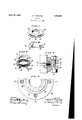
- Fig. I is a perspective view of my improved gasket.
- Fig. II is an exploded view of the parts constituting the asket.
- Fig. III is a dlagrammatic sectional view showing how the parts of the gasket are assemhled.
- Fig. IV is a fragmentary sectional view of a pipe flange jointwith my improved gasket clamped in place to seal the joint;
- Fig. V is a partial cross sectional View of the pipe flange joint taken as indicated by the arrows VV in Fig. IV.
- the numeral 10 comprehensively designates a flat gasket ring constructed after the manner described in the patent supra, i. e. with convolutions 11 of soft strip metal like aluminum, for example alternating with convolutions 12 of asbestos or other compressible packing material, and with the longitudinal corrugation 13 of one convolution of the strip metal interlapping with the corrugation 13 of another.
- I provide the flat ring 10 with a sheathing 15 of sheet copper or other relatively pliant meta-l capable of adapting itself conformatively to irregularities in the opposing surfaces of a pipe joint incident to compression of the gasket between them.
- the sheathing 15 comprises upper and lower disk sections 16, 17 formed respectively with complemental perpendicular flanges 18, 19 around central apertures, said flanges being adapted to interengage telescopically within the opening of the ring 10 after the manner illustrated in Fig. III.
- the flange 19 of the sheathing section 17 is expanded over the flange 18 of the companion sheathing component 16 as shown at 20 in Fig. IV.
- the upper sheathing section 16 is made to a diameter corresponding substantially to that of the ring 10; while the lower sheathing section 17 is made to a larger diameter with considerable circumferential projection beyond said ring 10.
- the sheathing 15 thus affords an extended flange, which, as shown in Figs. IV and V, is adapted to reach to the bolts 21 connecting the flanges 22, 23 of a pipe oint, the gasket being there- ⁇ by rendered self-centering.
- the sheathing 15 covers the ring 10 at the top and bottom and peripherally of its opening but not around its outside edge, so that said ring is left free to expand radially incident to 3 compression between the pi e flanges 22, 23.
- the compressible ring 10 is accorded highly efficientprotection' where it is most needed to wit: around its inner periphery which would ordinarily be directly exposed to the fluid passing through the pipe-the telescoping annular flanges 18, 19 of the sheathing components 16, 17 constituting, in effect, a double wall safe-guard or barrier against leakage at the indicated region.
- the sheathing o viously serves to protect the compressible ring 10'against inury and disintegration through rough handling during application-of the gasket to the pipe joint.
- the edges of the metal strip 11 engage the sheathin 15, which coacts with them(being pliant an soft) to resist expansion of the ring 10.
- a gasket comprising a flat ring of compressible material; and a protective sheathing of pliant sheet metal including a top disk of substantially the same diameter as the ring and a bottom disk of larger diameter, said disks having opposing perpendicular flanges around central openings engaging telescopically within the opening of the ring, and one of said disks being expanded over the other to hold the several parts in assembly.
- gasket comprising a lie t compressible ring wherein convolutions of soft strip metal, 4 having a longitudinal corrugation, alternate with convolutions of non-metallic packing material, and wherein the corrugation of one 'convolution of the strip metal interlaps with the corrugation of another; in combination with a protective sheathing of pliant sheet metal having circumfere itial projection beyond the compressible ring, but leaving its periphery open and free to expand.
- A- self-centering asket for pipe flange joints comprising a at compressible ring wherein convolutions of soft strip metal, having a longitudinal corrugation, alternate with convolutions of non-metallic packing material, and wherein-the corrugation of one con- Y volution of the strip metal interlaps with the corrugation of another; in combination with a protective sheathing of pliant sheet metal affording a circumferential flan e to reach to the bolts connecting the pipe anges.
Landscapes
- Engineering & Computer Science (AREA)
- General Engineering & Computer Science (AREA)
- Mechanical Engineering (AREA)
- Gasket Seals (AREA)
Description
April 26, 1932. IN 1,856,051
GASKET Filed Feb. 19, 1930 FIG-.112
W1 TNESSES' I N VEN TOR.-
Fry 2m I W I ATTORNEYS.
Patented Apr. 26, 1932 UNITED. STATES PATENT OFFICE HARRY I. I'BYLIN'G, 01 HIBCELNTVILLE, NEW JERSEY, ASSIGNOR TO FLEXITALLIC GASKET 60., OF CAMDEN, NEW JERSEY, A CORPORATION OF NEW JERSEY easxnr Application filed February 19,1930. Serial No. 429,530.
This invention relates to' compressible gas-jv kets intended for interposition between the flanges of pipe joints and the like for the purpose of insuring fluid tightness. More spe- & cifically, my invention has reference to the flat ring type of gasket shown and described in U. S. Patent #1,089,134, granted to Charles F. Hettinger on March 3, 1914,
wherein convolutions of strip metal with a 1 longitudinal corrugation alternate with conv'olutions of non-metallic packing materlal, g and wherein the corrugation of one convolution of the metallic strip interlaps with the corrugation of another.
The main objects of my invention are to enhance the efliciency of compressible gasket rings-particularly gasket rings of the kind referred toby providing them with a protective sheathing of pliant sheet metal; and
to render such gaskets self-centering by cireumferentially extending the sheathing beyond the compressible ring with formation of a flange adapted to reach substantially to the bolts connecting the opposing pipe flanges.
Other objects and attendant advantages will be manifest from the following description in connection with the attached drawings wherein Fig. I is a perspective view of my improved gasket.
Fig. II is an exploded view of the parts constituting the asket.
Fig. III is a dlagrammatic sectional view showing how the parts of the gasket are assemhled.
Fig. IV is a fragmentary sectional view of a pipe flange jointwith my improved gasket clamped in place to seal the joint; and
Fig. V is a partial cross sectional View of the pipe flange joint taken as indicated by the arrows VV in Fig. IV.
With more detailed reference to these illustrations, the numeral 10 comprehensively designates a flat gasket ring constructed after the manner described in the patent supra, i. e. with convolutions 11 of soft strip metal like aluminum, for example alternating with convolutions 12 of asbestos or other compressible packing material, and with the longitudinal corrugation 13 of one convolution of the strip metal interlapping with the corrugation 13 of another. In carrying out my invention, I provide the flat ring 10 with a sheathing 15 of sheet copper or other relatively pliant meta-l capable of adapting itself conformatively to irregularities in the opposing surfaces of a pipe joint incident to compression of the gasket between them. As shown, the sheathing 15 comprises upper and lower disk sections 16, 17 formed respectively with complemental perpendicular flanges 18, 19 around central apertures, said flanges being adapted to interengage telescopically within the opening of the ring 10 after the manner illustrated in Fig. III. To secure the several component parts of the gasket together, the flange 19 of the sheathing section 17 is expanded over the flange 18 of the companion sheathing component 16 as shown at 20 in Fig. IV. The upper sheathing section 16 is made to a diameter corresponding substantially to that of the ring 10; while the lower sheathing section 17 is made to a larger diameter with considerable circumferential projection beyond said ring 10. The sheathing 15 thus affords an extended flange, which, as shown in Figs. IV and V, is adapted to reach to the bolts 21 connecting the flanges 22, 23 of a pipe oint, the gasket being there- \by rendered self-centering.
It is to be noted particularly that the sheathing 15 covers the ring 10 at the top and bottom and peripherally of its opening but not around its outside edge, so that said ring is left free to expand radially incident to 3 compression between the pi e flanges 22, 23. In addition to being shiel ed top and bottom, the compressible ring 10 is accorded highly efficientprotection' where it is most needed to wit: around its inner periphery which would ordinarily be directly exposed to the fluid passing through the pipe-the telescoping annular flanges 18, 19 of the sheathing components 16, 17 constituting, in effect, a double wall safe-guard or barrier against leakage at the indicated region.
\Vhile I prefer to employ a compressible ring having the construction of the patent supra, I do not wish to be limited in this regard since compressible rings otherwise con structe'd may be readily substituted without departing from the spirit of my invention.
In addition to the advantages already pointed out; the sheathing o viously serves to protect the compressible ring 10'against inury and disintegration through rough handling during application-of the gasket to the pipe joint. When the gasket is compressed in a pipe joint, the edges of the metal strip 11 engage the sheathin 15, which coacts with them(being pliant an soft) to resist expansion of the ring 10.
Having thus described my invention, I claim:
1. A gasket comprisinga flat ring of compressible material; and a protective sheathing of pliant sheet metal including a top disk of substantially the same diameter as the ring and a bottom disk of larger diameter, said disks having opposing perpendicular flanges around central openings engaging telescopically within the opening of the ring, and one of said disks being expanded over the other to hold the several parts in assembly.
2. gasket comprising a lie t compressible ring wherein convolutions of soft strip metal, 4 having a longitudinal corrugation, alternate with convolutions of non-metallic packing material, and wherein the corrugation of one 'convolution of the strip metal interlaps with the corrugation of another; in combination with a protective sheathing of pliant sheet metal having circumfere itial projection beyond the compressible ring, but leaving its periphery open and free to expand.
3. A- self-centering asket for pipe flange joints comprising a at compressible ring wherein convolutions of soft strip metal, having a longitudinal corrugation, alternate with convolutions of non-metallic packing material, and wherein-the corrugation of one con- Y volution of the strip metal interlaps with the corrugation of another; in combination with a protective sheathing of pliant sheet metal affording a circumferential flan e to reach to the bolts connecting the pipe anges.
In testimony whereof, I have hereunto signed my name at Camden, New Jersey, this 14th day of February, 1930.
. HARRY F. FRYLING.
Priority Applications (1)
| Application Number | Priority Date | Filing Date | Title |
|---|---|---|---|
| US429530A US1856051A (en) | 1930-02-19 | 1930-02-19 | Gasket |
Applications Claiming Priority (1)
| Application Number | Priority Date | Filing Date | Title |
|---|---|---|---|
| US429530A US1856051A (en) | 1930-02-19 | 1930-02-19 | Gasket |
Publications (1)
| Publication Number | Publication Date |
|---|---|
| US1856051A true US1856051A (en) | 1932-04-26 |
Family
ID=23703645
Family Applications (1)
| Application Number | Title | Priority Date | Filing Date |
|---|---|---|---|
| US429530A Expired - Lifetime US1856051A (en) | 1930-02-19 | 1930-02-19 | Gasket |
Country Status (1)
| Country | Link |
|---|---|
| US (1) | US1856051A (en) |
Cited By (7)
| Publication number | Priority date | Publication date | Assignee | Title |
|---|---|---|---|---|
| US2462762A (en) * | 1944-10-19 | 1949-02-22 | Us Gasket Company | Gasket centering means |
| US2580546A (en) * | 1947-07-02 | 1952-01-01 | Us Gasket Company | Jacketed gasket |
| US3231288A (en) * | 1962-10-16 | 1966-01-25 | Ford Motor Co | Gasket assembly |
| US5803464A (en) * | 1994-05-09 | 1998-09-08 | Nippon Pillar Packing Co., Ltd. | Gland packing |
| US5921558A (en) * | 1997-04-15 | 1999-07-13 | Dana Corporation | High recovery combustion seal gasket |
| US20030047886A1 (en) * | 2000-06-27 | 2003-03-13 | Muehle Hubertus | Flap seal |
| WO2005120196A3 (en) * | 2004-06-04 | 2006-12-21 | Atlas Copco Secoroc Ab | Disassembleable washer device for down-hole drills |
-
1930
- 1930-02-19 US US429530A patent/US1856051A/en not_active Expired - Lifetime
Cited By (10)
| Publication number | Priority date | Publication date | Assignee | Title |
|---|---|---|---|---|
| US2462762A (en) * | 1944-10-19 | 1949-02-22 | Us Gasket Company | Gasket centering means |
| US2580546A (en) * | 1947-07-02 | 1952-01-01 | Us Gasket Company | Jacketed gasket |
| US3231288A (en) * | 1962-10-16 | 1966-01-25 | Ford Motor Co | Gasket assembly |
| US5803464A (en) * | 1994-05-09 | 1998-09-08 | Nippon Pillar Packing Co., Ltd. | Gland packing |
| US5921558A (en) * | 1997-04-15 | 1999-07-13 | Dana Corporation | High recovery combustion seal gasket |
| US20030047886A1 (en) * | 2000-06-27 | 2003-03-13 | Muehle Hubertus | Flap seal |
| US6719299B2 (en) * | 2000-06-27 | 2004-04-13 | Crane Process Flow Technologies Gmbh | Flap seal |
| WO2005120196A3 (en) * | 2004-06-04 | 2006-12-21 | Atlas Copco Secoroc Ab | Disassembleable washer device for down-hole drills |
| JP2008501907A (en) * | 2004-06-04 | 2008-01-24 | アトラス コプコ セコロク エイビー | Removable washer device for downhole drills |
| US20080067758A1 (en) * | 2004-06-04 | 2008-03-20 | Lyon Leland H | Disassembleable Washer Device for Down-Hole Drills |
Similar Documents
| Publication | Publication Date | Title |
|---|---|---|
| US2291709A (en) | Gasket construction | |
| US5427386A (en) | Protective seal for use in fluid flow lines and method therefor | |
| US2998986A (en) | Expansion joint | |
| US1896795A (en) | Gasket | |
| US3135538A (en) | Flanged pipe joint having one flange deflectable | |
| US4564220A (en) | Elastic gasket pipe coupling for pressurized plumbing systems | |
| US1856051A (en) | Gasket | |
| US805645A (en) | Gasket. | |
| US5823542A (en) | Spiral wound gasket | |
| US2201862A (en) | Pipe coupling | |
| US3124366A (en) | Ring-type gasket | |
| US3687487A (en) | Universal connector | |
| US5765876A (en) | Pipe coupling requiring low closing force | |
| JPS63280990A (en) | Butt joint for thin pipe | |
| US2489587A (en) | Connection for furnace members | |
| US3294408A (en) | Auxiliary, external, pressure seal for shank of plug valve | |
| US2022694A (en) | Tube | |
| US3854761A (en) | Sealing arrangement | |
| US2226494A (en) | Pressure vessel | |
| US2862729A (en) | Flexible bellows seal for flanged pipe joint | |
| US2145645A (en) | Pipe joint | |
| US605891A (en) | Steam-packing | |
| US1944135A (en) | Gasket | |
| US2194943A (en) | Armored machinery packing | |
| US1903029A (en) | Pipe coupling |