US5427386A - Protective seal for use in fluid flow lines and method therefor - Google Patents
Protective seal for use in fluid flow lines and method therefor Download PDFInfo
- Publication number
- US5427386A US5427386A US07/960,781 US96078192A US5427386A US 5427386 A US5427386 A US 5427386A US 96078192 A US96078192 A US 96078192A US 5427386 A US5427386 A US 5427386A
- Authority
- US
- United States
- Prior art keywords
- intumescent material
- seal
- channel
- gasket
- protective seal
- Prior art date
- Legal status (The legal status is an assumption and is not a legal conclusion. Google has not performed a legal analysis and makes no representation as to the accuracy of the status listed.)
- Expired - Lifetime
Links
- 230000001681 protective effect Effects 0.000 title claims abstract description 49
- 239000012530 fluid Substances 0.000 title claims abstract description 40
- 238000000034 method Methods 0.000 title abstract description 19
- 239000000463 material Substances 0.000 claims abstract description 113
- 238000000926 separation method Methods 0.000 claims abstract description 53
- 230000005465 channeling Effects 0.000 claims abstract description 31
- 230000004913 activation Effects 0.000 claims description 18
- 238000007789 sealing Methods 0.000 claims description 8
- OKTJSMMVPCPJKN-UHFFFAOYSA-N Carbon Chemical compound [C] OKTJSMMVPCPJKN-UHFFFAOYSA-N 0.000 claims description 7
- 229910002804 graphite Inorganic materials 0.000 claims description 7
- 239000010439 graphite Substances 0.000 claims description 7
- 239000002184 metal Substances 0.000 claims description 6
- 230000000717 retained effect Effects 0.000 claims description 4
- 230000000979 retarding effect Effects 0.000 claims description 2
- 238000002955 isolation Methods 0.000 description 9
- 239000003566 sealing material Substances 0.000 description 4
- 239000004593 Epoxy Substances 0.000 description 2
- 239000002131 composite material Substances 0.000 description 2
- 230000006835 compression Effects 0.000 description 2
- 238000007906 compression Methods 0.000 description 2
- 238000010276 construction Methods 0.000 description 2
- 230000032798 delamination Effects 0.000 description 2
- 238000005516 engineering process Methods 0.000 description 2
- 239000002360 explosive Substances 0.000 description 2
- 239000007789 gas Substances 0.000 description 2
- 238000012986 modification Methods 0.000 description 2
- 230000004048 modification Effects 0.000 description 2
- 229920000728 polyester Polymers 0.000 description 2
- 229920001296 polysiloxane Polymers 0.000 description 2
- -1 polytetrafluoroethylene Polymers 0.000 description 2
- 229920001343 polytetrafluoroethylene Polymers 0.000 description 2
- 239000004810 polytetrafluoroethylene Substances 0.000 description 2
- 229920002635 polyurethane Polymers 0.000 description 2
- 239000004814 polyurethane Substances 0.000 description 2
- 238000012545 processing Methods 0.000 description 2
- 239000000126 substance Substances 0.000 description 2
- 101100188555 Arabidopsis thaliana OCT6 gene Proteins 0.000 description 1
- 229910000831 Steel Inorganic materials 0.000 description 1
- 238000013459 approach Methods 0.000 description 1
- 230000015572 biosynthetic process Effects 0.000 description 1
- 230000008867 communication pathway Effects 0.000 description 1
- 238000011161 development Methods 0.000 description 1
- 239000000835 fiber Substances 0.000 description 1
- 230000009970 fire resistant effect Effects 0.000 description 1
- 239000000446 fuel Substances 0.000 description 1
- 239000003517 fume Substances 0.000 description 1
- 238000007429 general method Methods 0.000 description 1
- 239000011521 glass Substances 0.000 description 1
- 231100001261 hazardous Toxicity 0.000 description 1
- 238000009434 installation Methods 0.000 description 1
- 239000007788 liquid Substances 0.000 description 1
- 238000004519 manufacturing process Methods 0.000 description 1
- 230000002093 peripheral effect Effects 0.000 description 1
- 239000000047 product Substances 0.000 description 1
- 239000012783 reinforcing fiber Substances 0.000 description 1
- 239000000779 smoke Substances 0.000 description 1
- 239000010959 steel Substances 0.000 description 1
- 239000013589 supplement Substances 0.000 description 1
- 230000001988 toxicity Effects 0.000 description 1
- 231100000419 toxicity Toxicity 0.000 description 1
- 238000004804 winding Methods 0.000 description 1
Images


Classifications
-
- F—MECHANICAL ENGINEERING; LIGHTING; HEATING; WEAPONS; BLASTING
- F16—ENGINEERING ELEMENTS AND UNITS; GENERAL MEASURES FOR PRODUCING AND MAINTAINING EFFECTIVE FUNCTIONING OF MACHINES OR INSTALLATIONS; THERMAL INSULATION IN GENERAL
- F16L—PIPES; JOINTS OR FITTINGS FOR PIPES; SUPPORTS FOR PIPES, CABLES OR PROTECTIVE TUBING; MEANS FOR THERMAL INSULATION IN GENERAL
- F16L23/00—Flanged joints
- F16L23/16—Flanged joints characterised by the sealing means
- F16L23/18—Flanged joints characterised by the sealing means the sealing means being rings
- F16L23/22—Flanged joints characterised by the sealing means the sealing means being rings made exclusively of a material other than metal
-
- F—MECHANICAL ENGINEERING; LIGHTING; HEATING; WEAPONS; BLASTING
- F16—ENGINEERING ELEMENTS AND UNITS; GENERAL MEASURES FOR PRODUCING AND MAINTAINING EFFECTIVE FUNCTIONING OF MACHINES OR INSTALLATIONS; THERMAL INSULATION IN GENERAL
- F16J—PISTONS; CYLINDERS; SEALINGS
- F16J15/00—Sealings
- F16J15/002—Sealings comprising at least two sealings in succession
- F16J15/008—Sealings comprising at least two sealings in succession with provision to put out of action at least one sealing; One sealing sealing only on standstill; Emergency or servicing sealings
-
- F—MECHANICAL ENGINEERING; LIGHTING; HEATING; WEAPONS; BLASTING
- F16—ENGINEERING ELEMENTS AND UNITS; GENERAL MEASURES FOR PRODUCING AND MAINTAINING EFFECTIVE FUNCTIONING OF MACHINES OR INSTALLATIONS; THERMAL INSULATION IN GENERAL
- F16L—PIPES; JOINTS OR FITTINGS FOR PIPES; SUPPORTS FOR PIPES, CABLES OR PROTECTIVE TUBING; MEANS FOR THERMAL INSULATION IN GENERAL
- F16L23/00—Flanged joints
- F16L23/16—Flanged joints characterised by the sealing means
- F16L23/18—Flanged joints characterised by the sealing means the sealing means being rings
-
- Y—GENERAL TAGGING OF NEW TECHNOLOGICAL DEVELOPMENTS; GENERAL TAGGING OF CROSS-SECTIONAL TECHNOLOGIES SPANNING OVER SEVERAL SECTIONS OF THE IPC; TECHNICAL SUBJECTS COVERED BY FORMER USPC CROSS-REFERENCE ART COLLECTIONS [XRACs] AND DIGESTS
- Y10—TECHNICAL SUBJECTS COVERED BY FORMER USPC
- Y10S—TECHNICAL SUBJECTS COVERED BY FORMER USPC CROSS-REFERENCE ART COLLECTIONS [XRACs] AND DIGESTS
- Y10S277/00—Seal for a joint or juncture
- Y10S277/931—Seal including temperature responsive feature
- Y10S277/933—Chemical reaction or physical change of state
Definitions
- the present invention generally concerns protective seals and seal elements for use in fluid flow lines in order to reduce leakage at the interface between joined pieces forming the flow line when the flow line is subjected to elevated temperatures. More specifically, the present invention is directed to a protective seal device which expands under the influence of elevated temperatures, such as would occur during a fire, in order to fill separation gaps which might occur at joints in the pieces which form a flow line in order to reduce or eliminate the risk of leakage of material carried in the flow line. Correspondingly, the present invention also concerns a method of thermally protecting a fluid flow line upon exposure to elevated temperatures.
- Pipelines are usually constructed of a plurality of pieces or sections joined together to form a continuous fluid communication pathway.
- seals at the interfaces between joined pieces to prevent leakage of the fluid at the joint.
- seals are in the form of gaskets interposed between the joined pieces at their interface with the gaskets carrying compressible seal rings.
- isolation gaskets are used in critical service applications to electrically isolate adjacent pieces of the pipeline.
- an interface gasket may be employed in order to help reduce the risk of leakage from thermal separation of pipeline sections when subjected to elevated temperature such as occur in fire situations.
- An example of such is shown in U.S. patent application No. 801,770 entitled FIREPROOF GASKET FOR PIPE FLANGES.
- a gasket in the shape of a Belleville spring washer is disclosed, and the surfaces of this gasket are provided with annular seals. The gasket is compressed between the flanges of joined pipe segments in order to apply this seal therebetween. Should the pipe segments be separated by thermal expansion or stress on the system, the gaskets can flex to compensate for the separation gap.
- One example of an expandable gasket is shown in U.S. Pat. No. 1,825,962 issued 6 Oct. 1931 to Laird, and another example of an expandable gasket is shown in U.S. Pat. No. 1,965,273 issued 3 Jul. 1934 to Wilson.
- the gasket taught in the Laird patent is an annular gasket element formed of relatively soft metal configured in a frustoconical shape. This metallic washer is simply compressed between the flanges of a pair of joined pipe sections.
- Wilson discloses similar frustoconical metallic gaskets but includes a variety of configurations of auxiliary webs to enhance the seal between the flanges of two pipe sections.
- intumescent material in applications where there is the hazard of fire.
- intumescent material maybe a graphite catalyzed polyurethane, silicone, polyester or other such materials which expand in volume under the influence of elevated temperatures. This material can be compounded to activate at different temperatures so that it may only become activated under the influence of a fire.
- the primary use of such intumescent material has been to surround pipes and cables where they pass through walls or fire protected compartments in order to reduce or prevent the passage of smoke, fumes or fire through or around the pipes or cables.
- One such product is a pipe sleeve marketed by Fire Store, Ltd.
- Another object of the present invention is to provide a fluid seal and method therefore adapted to reduce or eliminate leakage caused at the interface between joined pieces in a pipeline when the interface is subjected to thermal separation should the flow line be subjected to a fire condition.
- a further object of the present invention is to provide a protective seal which can retro-fit onto existing pipeline systems without the need for extensive modification.
- Still a further object of the present invention is to provide a protective seal and method employing intumescent material directly at the interface between joined pieces of a flow line.
- Still a further object of the present invention is to provide a protective seal gasket which maybe interpose between the flanges of joined pieces in a flow line which gasket operates both to seal the interface but which employs intumescent material either in conjunction with the primary seal or as an auxiliary seal to protect the interface when subjected to thermal expansion caused by fire.
- the present invention contemplates a protective seal and a method for protecting a fluid flow line when exposed to elevated temperatures such as would occur during a fire.
- the protective seal element and the method is directing to retarding or eliminating leakage at a separation gap which results from thermal separation of joined pieces forming the flow line.
- the protective seal element utilizes an intumescent material in a channeling structure for the intumescent material.
- the intumescent material has a selected activation temperature such that the material expands at temperatures greater than the activation temperature.
- the channeling structure which is associated with the intumescent material is operative to channel the intumescent material into the separation gap when the joined pieces comprising the flow line are subjected to temperatures greater than the activation temperature.
- the protective seal may include at least one closed channel formed in at least one of the joined pieces, and the intumescent material is disposed within that channel.
- a seal element in the form of a ring seal, diaphragm or bladder may be disposed within the channel and positioned such that expansion of the intumescent material advances the seal element into the separation gap that results from thermal separation of the joined pieces.
- the protective seal element is constructed as a gasket having a flat gasket body with opposite side surfaces facing the joined pieces and a central opening formed therethrough to accommodate the flow of fluid.
- the channeling structure is then associated with the gasket body, and the intumescent material is disposed within the channeling structure.
- the channeling structure includes a channel formed in at least one, but preferably both, of the side surfaces of the gasket body in a closed loop surrounding the central opening.
- the channeling structure may be an annulus which extends around the gasket body with the intumescent material being retained in a region between the annulus and the gasket body.
- the gasket is of a spiral wound type wherein a strip of intumescent material and a strip of a channeling material are spirally wound around a core.
- the gasket body may be an isolation or a nonisolation type.
- the intumescent material may be disposed proximate to the bottom wall of the channel and a ring seal may be positioned in the channel above the intumescent material.
- the intumescent material may be contained within an expandable bladder, or a diaphragm element may be positioned between the ring seal and the intumescent material.
- Fiber bodies may be included within the intumescent material to increase its flow resistance.
- the general method according to the present invention contemplates the step of disposing intumescent material at a location proximate to the interface between joined pieces in a flow line and the step of channeling the intumescent material into the separation gap when the joined pieces are subjected to temperatures greater than the activation temperature of the intumescent material.
- This method may also include the step of providing a seal element proximate to the intumescent material and expanding the intumescent material to move the seal element into the separation gap.
- the method according to the present invention may channel the intumescent material either radially or axially into the separation gap with respect to the flow line.
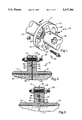
- FIG. 1 is a perspective view of a representative interface between the flanges of two pipeline segments showing an exemplary embodiment with a protective seal structure and method according to the present invention
- FIG. 2 is a cross-sectional view taken about lines 2--2 of FIG. 1 in a normally compressed state
- FIG. 3 is a cross-sectional view, similar to FIG. 2, but showing the protective seal in an activated state sealing a separation gap caused by thermal expansion due to exposure to elevated temperatures;
- FIGS. 4(a) and 4(b) are cross-sectional views showing an alternative embodiment of a protective seal according to the present invention respectively in an inactivated state and in an activated state;
- FIGS. 5(a) and 5(b) are cross-sectional views showing a third alternative embodiment of the present invention respectively in an inactivated state and in an activated state;
- FIGS. 6(a) and 6(b) are cross-sectional views showing a fourth alternative embodiment of the protective seal according to the present invention respectively in an inactivated state and in an activated state;
- FIG. 7 is a cross-sectional view of a flange connection the interface between two pipe segments showing the use of the present invention in conjunction with an isolation gasket;
- FIG. 8(a) is an enlarged cross-sectional view of a representative protective seal shown in FIG. 7 in an inactivated state and prior to compression;
- FIG. 8(b) is a cross-sectional view, similar to FIG. 8(a), showing the protective seal in a compressed state prior to activation;
- FIG. 8(c) is a cross-sectional view similar to FIG. 8(b) showing the protective seal of FIGS. 8(a) and 8(b) in an activated state sealing a separation gap after thermal expansion and separation;
- FIG. 9 is a cross-sectional view of another embodiment of the present invention used as an auxiliary seal in conjunction with an isolation gasket
- FIG. 10 is a cross-sectional view of another exemplary embodiment of the present invention in the form of a stamped gasket construction
- FIG. 11 is a front view in elevation of yet another exeplary embodiment of the present invention, here in the form of a spiral wound gasket;
- FIG. 12 is a cross-sectional view taken about lines 12--12 of FIG. 11;
- FIG. 13 is a cross-sectional view of a flange connection employing yet another gasket having an alternative embodiment of the present invention in an inactivated state;
- FIG. 14 is a cross-sectional view, similar to FIG. 13 but showing the gasket in an activated state.
- the present invention generally concerns the use of intumescent materials in forming a protective seal at the interface joined between joined pieces in a flow line, such as a pipeline system. Accordingly, the present invention also is directed to a method for protectively sealing the interface between such joined pieces in order to reduce or eliminate leakage of the fluid conveyed by the flow line should the flow line be subjected to elevated temperatures that would occur, for example, during a fire. Specifically, the present invention is directed to using intumescent material in combination with pipe flange gaskets in critical surface applications where the pipeline may be exposed to a fire hazard.
- a flow line 10 is formed by a pair of pipe segments 12 and 16 respectively provided with flanges 14 and 18 which may be bolted together at an interface joint 11, for example, by means of nut and bolt sets 20 extending through bores 22 formed in flanges 14 and 18.
- Flow line 10 is adapted to convey a fluid 24 of any nature, whether liquid or gas, with fluid 24 typically being of a type to be used in industry.
- a pair of protective seals 26 and 28 are formed directly in the facing surfaces of flanges 14 and 18, respectively in order to protect the interface against leakage should flow line 10 be subjected to elevated temperatures.
- seal 26 includes an annular channel 30 of rectangular cross-section is formed in surface 32 of flange 14.
- Channel 30 receives a mass 34 of intumescent material so that mass 34 surrounds axial flow path 36 of the flow line formed by pipe segments 12 and 16.
- annular channel 40 is formed through surface 42 of flange 18, and a mass 44 of intumescent material is disposed in annular channel 40.
- mass 44 surrounds flow path 36.
- annular channel 30 has a greater radius than annular channel 40 so that the channels 30 and 40 are offset with respect to one another. Accordingly, joint 38 is formed by flanges 14 and 18.
- seals 26 and 28 operate to maintain a seal between flanges 14 and 18 when interface joint 11 is subjected to elevated temperatures.
- FIG. 3 it may be seen that pipe segments 12 and 16 have been subjected to elevated temperatures, such as would exist in a fire, so that separation gap 46 is formed by the thermal expansion or warping of flanges 14 and 18 as well as thermal expansion of nut and bolt sets 22. Ordinarily, the fluid 24 conveyed by pipeline 10 would leak out separation gap 46 into the external environment. However, due to the expansive properties of the intumescent material forming masses 34 and 44, these masses swell under the influence of heat so that seals 26 and 28 are relatively maintained.
- the intumescent material used for masses 34 and 44 is accordingly formed of any suitable material known to expand under temperature increase at a selected activation temperature and which can withstand the temperatures normally associated with fire conditions.
- materials known in the art include graphite catalyzed polyurethane, silicone, polyester and the like.
- the present invention by the use of the term "intumescent material” contemplates these known expanding materials and similar such materials as are hereinafter developed in the industry.
- channels 30 and 40 act as channeling structures which operate to direct the expansive flow of the intumescent material into the separation gap 46 and, in this embodiment, directly against the surface of the opposed flange.
- mass 34 is channeled into separation gap 46 and against surface 42 of flange 18 while intumescent mass 44 is channeled into separation gap 46 and against surface 32 of flange 14.
- the intumescent material in FIGS. 1-3 is described to be the sealing means to fill the separation gap, and it can be used in this manner, it has been found preferably to use the intumescent material in conjunction with a normal ring seal element of graphite, polytetrafluoroethylene or similar material.
- the expansion property of the activated intumescent material is used to physically move the ring seal axially outwardly away from the flange and into the separation gap to maintain a sealed relationship at the joint 11.
- a representative channel 30 is formed in representative flange 14.
- a seal element such as a ring seal 50 is received in channel 30, and a layer of intumescent material 54 is positioned between seal 60 and bottom wall 52 of channel 30.
- An inverted U-shaped layer or diaphragm 56 is positioned between seal 50 and intumescent mass 54 with layer 56 having downwardly depending panels 58 which serve to retain intumescent mass 54 therein.
- flange 18 in the non-activated state, flange 18 abuts flange 14 so that flanges 14 and 18 are relatively sealed with respect to one another.
- flanges 14 and 18 when flanges 14 and 18 are subjected to elevated temperatures, as is shown in FIG. 4(b), flanges 14 and 18 move apart from one another to create separation gap 46.
- Intumescent mass 54 expands against diaphragm 56 which in turn acts on ring seal 50 to physically move ring seal 50 outwardly of channel 30 so that it is maintained in abutting relationship with flange 18 under the expansion force of the intumescent material.
- FIGS. 5(a) and 5(b) show a similar structure to FIGS. 4(a) and 4(b).
- intumescent mass 64 is enclosed within a flexible bladder 66 and is disposed on the bottom of channel 30 formed in flange 14.
- Ring seal 50 is again provided and, as is shown in FIG. 5(b), when separation gap 46 results from thermal expansion, bladder 66 expands along with intumescent material 64 to physically move seal 50 outwardly of channel 50 thereby retaining it in contact with flange 18.
- FIG. 6(a) and 6(b) Yet another alternative embodiment of the protective seal according to the present invention is shown in FIG. 6(a) and 6(b).
- This seal is similar to that shown in FIGS. 1-3 with the exception that intumescent mass 74 is shown retained in an enlarged inverted U-shaped diaphragm 76 that is then positioned in channel 30, and ring seal 50 is eliminated.
- intumescent mass 74 expands to cause diaphragm 76 to maintain a sealed relationship with flange 18 thus effectively sealing separation gap 46.
- diaphragm 76 is constructed of a material that will seal against flange 18.
- FIGS. 7 and 8 show the protective seal utilizing the intumescent material according to the present invention in an isolation gasket 100 that is positioned between flanges 114 and 118 of pipe segments 112 and 116 of flow line 110.
- Isolation gasket 100 may be of a type that is disclosed in U.S. Pat. No. 4,776,600 issued 11 Oct. 1988 to Kohn.
- This isolation gasket includes a central metallic core 102 which is sandwiched between two high elastic modulus glass reinforced epoxy laminates 103 and 104 in order to electrically isolate pipe segments 112 and 116 from one another.
- a central metallic core 102 which is sandwiched between two high elastic modulus glass reinforced epoxy laminates 103 and 104 in order to electrically isolate pipe segments 112 and 116 from one another.
- gasket 100 has a pair of dove-tail channels 130 formed in opposite side surfaces, and a ring seal 150 may be received in each channel 130.
- a mass of intumescent material 154 is interposed at the bottom of channel 130 between bottom wall 152 and seal 150 and a diaphragm 156 is disposed between intumescent mass 154 and seal 150.
- intumescent mass 154 activates to expand thereby forcing ring seal 150 into contact with flange 114 notwithstanding the formation of separation gap 146. Furthermore, with reference to FIG. 8(c), it may be seen that, where an isolation gasket 100 is used, the heat of the external environment sometimes delaminates epoxy layer 103 from metal core 102. In this situation, intumescent mass 154 can migrate into the delamination space 148 so as to assist in preventing or reducing any leakage of fluid through this space created by the delamination of the gasket layers.
- the dove-tail shape of channels 130 helps retain a seal for both ring seal 150 and the intumescent material 154 contained therein.
- FIGS. 7 and 8 show the use of intumescent material with a primary seal in a gasket structure
- the protective seal could be formed as an auxiliary protective seal to supplement the normal primary seal for the interface joint between the joined pieces.
- primary seal 200 is provided by a gasket 202 with seal 200 being in the form of a ring seal received in channel 204 of gasket 200.
- An auxiliary seal 210 is provided in the form of a flexible bladder 212 filled with intumescent material 214 that, in this embodiment, includes reinforcing fibers 216.
- primary seal 200 seals against flange 218 to prevent egress of fluid.
- auxiliary 210 expands to maintain the seal between gasket 202 and flange 218.
- gasket 220 is formed as a stamped piece of metal or other formable substance.
- a pair of oppositely-facing, concentric channel structures 222 and 224 are produced in surrounding relationship to axial opening 226 that is adapted to permit flow of fluid therethrough when gasket 220 is interposed in a flow line.
- a first seal element 232 is disposed in channel structure 222, and a second seal element 234 is disposed in channel structure 224.
- Seal element 232 is constructed as a ring seal having an outer layer 240 of sealing material, such as graphite, polytetrafluoroethylene, etc., bonded to an inner layer 242.
- seal element 234 is constructed to have an outer layer 244 of sealing material and an inner layer 246 of intumescent material bonded together.
- seal elements 232 and 234 act to prevent leakage of fluid.
- these layers 242 and 246 expand to drive layers 240 and 244 into any resulting separation gap thereby to help reduce or prevent leakage of fluid from the damaged flow line.
- gasket 250 has an inner annulus or ring core 252 formed of suitable material, such as metal.
- a three-layered composite strip comprising a strip 254 of metal, a strip 256 of graphite (or other sealing material) and a strip 258 of intumescent material is then wound spoolwise around core 252 to create an annular seal region 260 for gasket 250.
- An outer annulus 262 is used to retain the spiral winding of the composite strip and to provide an outer boundary for gasket 250.
- strips 254 and 256 act as channeling structures for the intumescent material of strip 258 in order to channel the intumescent material axially upon activation. Either of strips 254 or 256 could be eliminated from this structure, however, without departing from the scope of the invention. It is useful, though, to employ a sealing material of the types known in the art, and as discussed above, as the channeling strip since it can also function as a seal during normal use to prevent leakage of fluid from the flow line.
- yet another embodiment of the present invention provides a gasket 300 with a metallic rim in the form of annulus 302 which surrounds the peripheral edge 304 of gasket 300.
- Annulus 302 encloses a mass 324 of intumescent material, and primary seals 310 and 312 are provided for normally sealing gasket 300 between flanges 312 and 316.
- FIG. 14 it may be seen that, upon activation, sidewalls 303 of annulus 302 will expand due to the expansion of intumescent material 324 to bear against flanges 312 and 316. Such expansion then channels intumescent material 324 radially inwardly thereby maintaining the integrity of the seal at joint 328.
- the method according to the present invention contemplates a method of protecting a fluid flow line that is operative to convey a fluid in order to retard leakage of the fluid at a separation gap which results from thermal separation at an interface between joined pieces forming the flow line when the joined pieces are subjected to a high temperature external environment.
- This method broadly includes the step of disposing intumescent material at a location proximate to the interface between the joined pieces with this intumescent material having a selective activation temperature such that the intumescent material expands at temperatures greater than the activation temperature.
- this method includes the step of channeling the intumescent material into the separation gap resulting when the joined pieces are subjected to temperatures greater than the activation temperature of the intumescent material.
- the intumescent material may be channeled either axially or radially (with respect to the direction of the flow line) into the separation gap according to this method.
- the more detailed method may include the steps of providing a seal element and expanding the intumescent material to advance the seal element into the separation gap.
Abstract
Description
Claims (18)
Priority Applications (2)
| Application Number | Priority Date | Filing Date | Title |
|---|---|---|---|
| US07/960,781 US5427386A (en) | 1992-10-14 | 1992-10-14 | Protective seal for use in fluid flow lines and method therefor |
| PCT/US1993/008266 WO1994009295A1 (en) | 1992-10-14 | 1993-09-02 | Protective seal for use in fluid flow lines and method therefor |
Applications Claiming Priority (1)
| Application Number | Priority Date | Filing Date | Title |
|---|---|---|---|
| US07/960,781 US5427386A (en) | 1992-10-14 | 1992-10-14 | Protective seal for use in fluid flow lines and method therefor |
Publications (1)
| Publication Number | Publication Date |
|---|---|
| US5427386A true US5427386A (en) | 1995-06-27 |
Family
ID=25503618
Family Applications (1)
| Application Number | Title | Priority Date | Filing Date |
|---|---|---|---|
| US07/960,781 Expired - Lifetime US5427386A (en) | 1992-10-14 | 1992-10-14 | Protective seal for use in fluid flow lines and method therefor |
Country Status (2)
| Country | Link |
|---|---|
| US (1) | US5427386A (en) |
| WO (1) | WO1994009295A1 (en) |
Cited By (35)
| Publication number | Priority date | Publication date | Assignee | Title |
|---|---|---|---|---|
| US5851109A (en) * | 1997-01-22 | 1998-12-22 | Warren Rupp, Inc. | Spacer and shim assembly for fluid powered diaphragm pumps |
| US5957508A (en) * | 1996-08-16 | 1999-09-28 | Robert Bosch Gmbh | Sealing device |
| US6128874A (en) * | 1999-03-26 | 2000-10-10 | Unifrax Corporation | Fire resistant barrier for dynamic expansion joints |
| US6402159B1 (en) | 1997-04-08 | 2002-06-11 | Gary A. Kohn | Dielectric gasket |
| US20030075876A1 (en) * | 2000-02-23 | 2003-04-24 | Xomox International Gmbh & Co. | Seal system |
| US6669205B2 (en) | 2001-03-28 | 2003-12-30 | Parker-Hannifin Corporation | Retainer gasket with pressure relief vents |
| US6695357B2 (en) | 2001-03-28 | 2004-02-24 | Parker-Hannifin Corporation | Threaded pipe connection having a retainer gasket with pressure relief vents |
| US20040262851A1 (en) * | 2003-06-25 | 2004-12-30 | Matt Tones | Rebuildable composite seal |
| US20050046121A1 (en) * | 2003-08-26 | 2005-03-03 | Jones Jay M. | Retainer gasket construction |
| US20050044689A1 (en) * | 2003-08-26 | 2005-03-03 | Yetter William P. | Retainer gasket construction |
| US6862852B1 (en) * | 1999-08-02 | 2005-03-08 | Beele Engineering, B.V. | Sealing system and gasket therefor |
| US20060038357A1 (en) * | 2004-08-23 | 2006-02-23 | Kamibayashiyama Julian F | Wedging retainer gasket construction |
| US20060061046A1 (en) * | 2003-01-16 | 2006-03-23 | Garlock France Sas | Sealing joint with laminated internal structure for very high temperatures |
| US20060220324A1 (en) * | 2005-04-04 | 2006-10-05 | Anderson Thornton J | Isolation gasket, system and method of manufacture |
| US20070267868A1 (en) * | 2003-10-23 | 2007-11-22 | Peter Holzheu | Flanged Joint |
| US20080231000A1 (en) * | 2005-08-23 | 2008-09-25 | Zhejiang China Valve Co., Ltd | Trapezoid-Sectional Annular Thermally-Assisted Sealing Arrangement |
| US20090243290A1 (en) * | 2008-03-28 | 2009-10-01 | Corrosion Control Corporation D/B/A Pikotek | Isolation Gasket, System, and Method of Manufacture |
| US20100013220A1 (en) * | 2008-07-16 | 2010-01-21 | General Electric Company | Extrusion resistant gasket face seal |
| US20100219589A1 (en) * | 2007-05-16 | 2010-09-02 | Aakesson Niklas | Seal with fire protection |
| US20110072634A1 (en) * | 2005-04-08 | 2011-03-31 | Kamibayashiyama Julian F | Wedging retainer gasket construction |
| US20110140371A1 (en) * | 2009-09-03 | 2011-06-16 | Christiaan Phillipus Strydom | Flange sealing system |
| US20130020768A1 (en) * | 2009-12-09 | 2013-01-24 | Robert Bosch Gmbh | Arrangement and method for sealing off a joint area between a first joint partner and a second joint partner |
| US20130220668A1 (en) * | 2012-02-29 | 2013-08-29 | Hamilton Sundstrand Corporation | Low electrical resistance bond |
| US20160040810A1 (en) * | 2014-08-08 | 2016-02-11 | Rohr, Inc. | Bolted duct joints |
| US20170254455A1 (en) * | 2014-09-23 | 2017-09-07 | Fr. Jacob Söhne Gmbh & Co. Kg | Folded sealing ring and device for detecting components of a folded sealing ring |
| US9879781B2 (en) * | 2015-03-06 | 2018-01-30 | Ford Global Technologies, Llc | Plated sealing system for vehicle assembly |
| US20180051634A1 (en) * | 2016-08-18 | 2018-02-22 | Pratt & Whitney Canada Corp. | System and method for sealing a fluid system in a safety condition |
| US20180094756A1 (en) * | 2016-10-05 | 2018-04-05 | Garlock Pipeline Technologies, Inc. | Gasket with electrical isolating coatings |
| US10001235B2 (en) | 2014-01-29 | 2018-06-19 | Garlock Pipeline Technologies, Inc. | Sealing system having interlocking inner diameter seal element to resist pressure changes |
| US10197200B2 (en) | 2014-07-01 | 2019-02-05 | Lamons Gasket Company | Electrically isolating, fire-safe sealing element |
| USD877838S1 (en) * | 2018-10-20 | 2020-03-10 | Thomas William Bird | Pool Ball Rack |
| JP2020101220A (en) * | 2018-12-21 | 2020-07-02 | 株式会社藤井合金製作所 | Seal structure of connection part |
| US10920914B2 (en) | 2014-01-29 | 2021-02-16 | Garlock Pipeline Technologies, Inc. | Sealing system having interlocking inner diameter seal element to resist pressure changes |
| US11408544B2 (en) * | 2019-10-31 | 2022-08-09 | Eaton Intelligent Power Limited | Fluid coupling |
| US11898637B2 (en) | 2016-10-05 | 2024-02-13 | Gpt Industries, Llc | Gasket with electrical isolating coatings |
Families Citing this family (3)
| Publication number | Priority date | Publication date | Assignee | Title |
|---|---|---|---|---|
| NL1006313C2 (en) * | 1997-06-13 | 1998-12-15 | Wavin Bv | Pipe connection. |
| WO2016135432A1 (en) * | 2015-02-23 | 2016-09-01 | DALGARNO, Kenneth, James | Fire resistant ducting systems |
| US10976070B1 (en) | 2017-03-31 | 2021-04-13 | Albers Mechanical Contractors, Inc. | Foam core duct system protected by metal sleeves with integral flanges |
Citations (22)
| Publication number | Priority date | Publication date | Assignee | Title |
|---|---|---|---|---|
| US1825962A (en) * | 1927-07-30 | 1931-10-06 | Wilbur G Laird | Gasket |
| US1965273A (en) * | 1926-04-24 | 1934-07-03 | Wilson Rings Company | Sealing and locking device |
| US2462493A (en) * | 1944-07-19 | 1949-02-22 | Paul A Dewhirst | Seal for pipe-line fittings |
| US3836183A (en) * | 1971-03-17 | 1974-09-17 | Pike And Foundry Co | Flange joint |
| US3869132A (en) * | 1973-07-18 | 1975-03-04 | Pressure Science Inc | Fire resistant sealing ring combination |
| US3930656A (en) * | 1974-02-22 | 1976-01-06 | Parker-Hannifin Corporation | Sealed joint and gasket therefor |
| US4109923A (en) * | 1976-04-14 | 1978-08-29 | Kempchen & Co. Gmbh | Pipe joint |
| US4268070A (en) * | 1978-06-01 | 1981-05-19 | Adams Harold R | Orifice flange clamp |
| US4288105A (en) * | 1979-02-21 | 1981-09-08 | Resistoflex Corporation | Pipe union with both pre-load dependent and independent seals |
| US4406467A (en) * | 1982-12-06 | 1983-09-27 | Atlantic Richfield Company | High pressure electrical isolation flange gasket |
| GB2141187A (en) * | 1983-06-06 | 1984-12-12 | Cyril Xavier Latty | Sealing element |
| JPS60101361A (en) * | 1983-11-07 | 1985-06-05 | Adachi Shin Sangyo Kk | Sealing method of vessel |
| US4669759A (en) * | 1986-01-14 | 1987-06-02 | Harbeke Gerold J | Fire-stop stack fitting and method of using same |
| US4673187A (en) * | 1985-07-09 | 1987-06-16 | Fluorocarbon Company | Bimetallic spiral wound gasket |
| US4690438A (en) * | 1984-12-17 | 1987-09-01 | Kraftwerk Union Aktiengesellschaft | Flange connection |
| US4776600A (en) * | 1987-11-23 | 1988-10-11 | Pikotek, Inc. | Dielectric pipe flange gasket |
| US4790544A (en) * | 1983-12-19 | 1988-12-13 | Raychem Gmbh | Expansible seal |
| US4795166A (en) * | 1985-04-10 | 1989-01-03 | Feodor Burgmann Dichtungswerke Gmbh & Co. | Sealing gasket |
| US4826220A (en) * | 1988-04-11 | 1989-05-02 | Swr, Inc. | Means for connecting successive sections of tubular elements |
| JPH01224571A (en) * | 1988-03-03 | 1989-09-07 | Nippon Pillar Packing Co Ltd | Spiral gasket |
| US4871181A (en) * | 1987-04-09 | 1989-10-03 | Metex Corporation | Reinforced squeak free seal for exhaust couplings |
| GB2244782A (en) * | 1990-05-23 | 1991-12-11 | Kempchen & Co Gmbh | Fireproof sealing system for bolted flanges |
-
1992
- 1992-10-14 US US07/960,781 patent/US5427386A/en not_active Expired - Lifetime
-
1993
- 1993-09-02 WO PCT/US1993/008266 patent/WO1994009295A1/en active Application Filing
Patent Citations (22)
| Publication number | Priority date | Publication date | Assignee | Title |
|---|---|---|---|---|
| US1965273A (en) * | 1926-04-24 | 1934-07-03 | Wilson Rings Company | Sealing and locking device |
| US1825962A (en) * | 1927-07-30 | 1931-10-06 | Wilbur G Laird | Gasket |
| US2462493A (en) * | 1944-07-19 | 1949-02-22 | Paul A Dewhirst | Seal for pipe-line fittings |
| US3836183A (en) * | 1971-03-17 | 1974-09-17 | Pike And Foundry Co | Flange joint |
| US3869132A (en) * | 1973-07-18 | 1975-03-04 | Pressure Science Inc | Fire resistant sealing ring combination |
| US3930656A (en) * | 1974-02-22 | 1976-01-06 | Parker-Hannifin Corporation | Sealed joint and gasket therefor |
| US4109923A (en) * | 1976-04-14 | 1978-08-29 | Kempchen & Co. Gmbh | Pipe joint |
| US4268070A (en) * | 1978-06-01 | 1981-05-19 | Adams Harold R | Orifice flange clamp |
| US4288105A (en) * | 1979-02-21 | 1981-09-08 | Resistoflex Corporation | Pipe union with both pre-load dependent and independent seals |
| US4406467A (en) * | 1982-12-06 | 1983-09-27 | Atlantic Richfield Company | High pressure electrical isolation flange gasket |
| GB2141187A (en) * | 1983-06-06 | 1984-12-12 | Cyril Xavier Latty | Sealing element |
| JPS60101361A (en) * | 1983-11-07 | 1985-06-05 | Adachi Shin Sangyo Kk | Sealing method of vessel |
| US4790544A (en) * | 1983-12-19 | 1988-12-13 | Raychem Gmbh | Expansible seal |
| US4690438A (en) * | 1984-12-17 | 1987-09-01 | Kraftwerk Union Aktiengesellschaft | Flange connection |
| US4795166A (en) * | 1985-04-10 | 1989-01-03 | Feodor Burgmann Dichtungswerke Gmbh & Co. | Sealing gasket |
| US4673187A (en) * | 1985-07-09 | 1987-06-16 | Fluorocarbon Company | Bimetallic spiral wound gasket |
| US4669759A (en) * | 1986-01-14 | 1987-06-02 | Harbeke Gerold J | Fire-stop stack fitting and method of using same |
| US4871181A (en) * | 1987-04-09 | 1989-10-03 | Metex Corporation | Reinforced squeak free seal for exhaust couplings |
| US4776600A (en) * | 1987-11-23 | 1988-10-11 | Pikotek, Inc. | Dielectric pipe flange gasket |
| JPH01224571A (en) * | 1988-03-03 | 1989-09-07 | Nippon Pillar Packing Co Ltd | Spiral gasket |
| US4826220A (en) * | 1988-04-11 | 1989-05-02 | Swr, Inc. | Means for connecting successive sections of tubular elements |
| GB2244782A (en) * | 1990-05-23 | 1991-12-11 | Kempchen & Co Gmbh | Fireproof sealing system for bolted flanges |
Cited By (54)
| Publication number | Priority date | Publication date | Assignee | Title |
|---|---|---|---|---|
| US5957508A (en) * | 1996-08-16 | 1999-09-28 | Robert Bosch Gmbh | Sealing device |
| US5851109A (en) * | 1997-01-22 | 1998-12-22 | Warren Rupp, Inc. | Spacer and shim assembly for fluid powered diaphragm pumps |
| US6402159B1 (en) | 1997-04-08 | 2002-06-11 | Gary A. Kohn | Dielectric gasket |
| US6128874A (en) * | 1999-03-26 | 2000-10-10 | Unifrax Corporation | Fire resistant barrier for dynamic expansion joints |
| US6862852B1 (en) * | 1999-08-02 | 2005-03-08 | Beele Engineering, B.V. | Sealing system and gasket therefor |
| US20030075876A1 (en) * | 2000-02-23 | 2003-04-24 | Xomox International Gmbh & Co. | Seal system |
| US6669205B2 (en) | 2001-03-28 | 2003-12-30 | Parker-Hannifin Corporation | Retainer gasket with pressure relief vents |
| US6695357B2 (en) | 2001-03-28 | 2004-02-24 | Parker-Hannifin Corporation | Threaded pipe connection having a retainer gasket with pressure relief vents |
| US20060061046A1 (en) * | 2003-01-16 | 2006-03-23 | Garlock France Sas | Sealing joint with laminated internal structure for very high temperatures |
| US7458587B2 (en) * | 2003-01-16 | 2008-12-02 | Garlock France Sas | Sealing joint with laminated internal structure for very high temperatures |
| US20040262851A1 (en) * | 2003-06-25 | 2004-12-30 | Matt Tones | Rebuildable composite seal |
| US7401404B2 (en) | 2003-08-26 | 2008-07-22 | Parker-Hannifin Corporation | Retainer gasket construction |
| US20050046121A1 (en) * | 2003-08-26 | 2005-03-03 | Jones Jay M. | Retainer gasket construction |
| US20050044689A1 (en) * | 2003-08-26 | 2005-03-03 | Yetter William P. | Retainer gasket construction |
| US7677611B2 (en) * | 2003-10-23 | 2010-03-16 | Fey Lamellenringe GmbH & Co., KG | Flanged joint |
| US20070267868A1 (en) * | 2003-10-23 | 2007-11-22 | Peter Holzheu | Flanged Joint |
| US20060038357A1 (en) * | 2004-08-23 | 2006-02-23 | Kamibayashiyama Julian F | Wedging retainer gasket construction |
| WO2006107798A1 (en) * | 2005-04-04 | 2006-10-12 | Corrosion Control Corp. D/B/A Pikotek | Isolation gasket, system and method of manufacture |
| US20060220324A1 (en) * | 2005-04-04 | 2006-10-05 | Anderson Thornton J | Isolation gasket, system and method of manufacture |
| US20110072634A1 (en) * | 2005-04-08 | 2011-03-31 | Kamibayashiyama Julian F | Wedging retainer gasket construction |
| US20080231000A1 (en) * | 2005-08-23 | 2008-09-25 | Zhejiang China Valve Co., Ltd | Trapezoid-Sectional Annular Thermally-Assisted Sealing Arrangement |
| US8910949B2 (en) * | 2007-05-16 | 2014-12-16 | Roxtec Ab | Seal with fire protection |
| US20100219589A1 (en) * | 2007-05-16 | 2010-09-02 | Aakesson Niklas | Seal with fire protection |
| US20110266755A1 (en) * | 2008-03-28 | 2011-11-03 | Corrosion Control Corporation D/B/A Pikotek | Isolation gasket, system and method of manufacture |
| US7976074B2 (en) * | 2008-03-28 | 2011-07-12 | Corrosion Control Corporation | Isolation gasket system incorporating secondary seal and compression limiter |
| US8678398B2 (en) * | 2008-03-28 | 2014-03-25 | Garlock Pipeline Technologies, Inc. | Isolation gasket, system and method of manufacture |
| US20090243290A1 (en) * | 2008-03-28 | 2009-10-01 | Corrosion Control Corporation D/B/A Pikotek | Isolation Gasket, System, and Method of Manufacture |
| US20100013220A1 (en) * | 2008-07-16 | 2010-01-21 | General Electric Company | Extrusion resistant gasket face seal |
| US8191933B2 (en) * | 2008-07-16 | 2012-06-05 | General Electric Company | Extrusion resistant gasket face seal |
| US20110140371A1 (en) * | 2009-09-03 | 2011-06-16 | Christiaan Phillipus Strydom | Flange sealing system |
| US9206902B2 (en) * | 2009-09-03 | 2015-12-08 | Christiaan Phillipus Strydom | Flange sealing system |
| US8967626B2 (en) * | 2009-12-09 | 2015-03-03 | Robert Bosch Gmbh | Arrangement and method for sealing off a joint area between a first joint partner and a second joint partner |
| US20130020768A1 (en) * | 2009-12-09 | 2013-01-24 | Robert Bosch Gmbh | Arrangement and method for sealing off a joint area between a first joint partner and a second joint partner |
| US20130220668A1 (en) * | 2012-02-29 | 2013-08-29 | Hamilton Sundstrand Corporation | Low electrical resistance bond |
| US8816221B2 (en) * | 2012-02-29 | 2014-08-26 | Hamilton Sundstrand Corporation | Low electrical resistance bond |
| US11619331B2 (en) | 2014-01-29 | 2023-04-04 | Garlock Pipeline Technologies, Inc. | Gasket having interlocked inner diameter seal element |
| US10001235B2 (en) | 2014-01-29 | 2018-06-19 | Garlock Pipeline Technologies, Inc. | Sealing system having interlocking inner diameter seal element to resist pressure changes |
| US10920914B2 (en) | 2014-01-29 | 2021-02-16 | Garlock Pipeline Technologies, Inc. | Sealing system having interlocking inner diameter seal element to resist pressure changes |
| US10197200B2 (en) | 2014-07-01 | 2019-02-05 | Lamons Gasket Company | Electrically isolating, fire-safe sealing element |
| US20160040810A1 (en) * | 2014-08-08 | 2016-02-11 | Rohr, Inc. | Bolted duct joints |
| US10287990B2 (en) * | 2014-08-08 | 2019-05-14 | Rohr, Inc. | Bleed system bolted duct with recessed seals |
| US11118513B2 (en) | 2014-08-08 | 2021-09-14 | Rohr, Inc. | Bolted duct joints |
| US20170254455A1 (en) * | 2014-09-23 | 2017-09-07 | Fr. Jacob Söhne Gmbh & Co. Kg | Folded sealing ring and device for detecting components of a folded sealing ring |
| US9879781B2 (en) * | 2015-03-06 | 2018-01-30 | Ford Global Technologies, Llc | Plated sealing system for vehicle assembly |
| US10823290B2 (en) | 2015-03-06 | 2020-11-03 | Ford Global Technologies, Llc | Plated sealing system for vehicle assembly |
| US20180051634A1 (en) * | 2016-08-18 | 2018-02-22 | Pratt & Whitney Canada Corp. | System and method for sealing a fluid system in a safety condition |
| US10767565B2 (en) * | 2016-08-18 | 2020-09-08 | Pratt & Whitney Canada Corp. | System and method for sealing a fluid system in a safety condition |
| US11015710B2 (en) | 2016-10-05 | 2021-05-25 | Garlock Pipeline Technologies, Inc. | Gasket with electrical isolating coatings |
| US11543030B2 (en) | 2016-10-05 | 2023-01-03 | Garlock Pipeline Technologies, Inc. | Gasket with electrical isolating coatings |
| US20180094756A1 (en) * | 2016-10-05 | 2018-04-05 | Garlock Pipeline Technologies, Inc. | Gasket with electrical isolating coatings |
| US11898637B2 (en) | 2016-10-05 | 2024-02-13 | Gpt Industries, Llc | Gasket with electrical isolating coatings |
| USD877838S1 (en) * | 2018-10-20 | 2020-03-10 | Thomas William Bird | Pool Ball Rack |
| JP2020101220A (en) * | 2018-12-21 | 2020-07-02 | 株式会社藤井合金製作所 | Seal structure of connection part |
| US11408544B2 (en) * | 2019-10-31 | 2022-08-09 | Eaton Intelligent Power Limited | Fluid coupling |
Also Published As
| Publication number | Publication date |
|---|---|
| WO1994009295A1 (en) | 1994-04-28 |
Similar Documents
| Publication | Publication Date | Title |
|---|---|---|
| US5427386A (en) | Protective seal for use in fluid flow lines and method therefor | |
| US5564715A (en) | Tandem seal device for flow line applications | |
| US4288105A (en) | Pipe union with both pre-load dependent and independent seals | |
| US5407214A (en) | Fire barrier gasket seal | |
| US3869132A (en) | Fire resistant sealing ring combination | |
| EP2698573B1 (en) | Isolation gasket | |
| AU621443B2 (en) | Fire-stopping apparatus | |
| US4796401A (en) | Composite fire stop device | |
| US4776600A (en) | Dielectric pipe flange gasket | |
| US6978807B1 (en) | Water stop for a line installation in a pre-insulated pipeline | |
| EP0932795B1 (en) | Double walled pipe structures | |
| US7143788B2 (en) | High temperature line expansion installation with bellows | |
| US5645284A (en) | Gasket | |
| US4058328A (en) | Heat-responsively self-sealing protective jacket for expansion joints | |
| US7028717B1 (en) | Water stop for a loop installation in a pre-insulated pipeline | |
| US3246917A (en) | Flexible diaphragm type conduit seal | |
| US2201862A (en) | Pipe coupling | |
| US2828987A (en) | Pressure seals for pipe flanges | |
| US20140353927A1 (en) | Fire and chemical resistant gasket | |
| US20120146324A1 (en) | Watertight, Expandible and Contractible Pipe Joint for High Temperature Insulated Piping | |
| US6394140B1 (en) | Gasket | |
| GB2324845A (en) | Pipeline joint for double-skinned pipes | |
| AU8321687A (en) | Fire resistant pipe couplings | |
| GB2043813A (en) | Fire Resistant Pipe Joints | |
| WO2009029878A1 (en) | Seal device having an inner diameter seal |
Legal Events
| Date | Code | Title | Description |
|---|---|---|---|
| AS | Assignment |
Owner name: CORROSION CONTROL CORP. D/B/A PIKOTEK, COLORADO Free format text: ASSIGNMENT OF ASSIGNORS INTEREST.;ASSIGNOR:BREAKER, JOHN V.;REEL/FRAME:006380/0263 Effective date: 19921014 |
|
| STCF | Information on status: patent grant |
Free format text: PATENTED CASE |
|
| FPAY | Fee payment |
Year of fee payment: 4 |
|
| FEPP | Fee payment procedure |
Free format text: PAYOR NUMBER ASSIGNED (ORIGINAL EVENT CODE: ASPN); ENTITY STATUS OF PATENT OWNER: LARGE ENTITY |
|
| FPAY | Fee payment |
Year of fee payment: 8 |
|
| AS | Assignment |
Owner name: BANK OF AMERICA, N.A., GEORGIA Free format text: SECURITY AGREEMENT;ASSIGNOR:CORROSION CONTROL CORPORATION;REEL/FRAME:014754/0587 Effective date: 20031114 |
|
| FEPP | Fee payment procedure |
Free format text: PAT HOLDER NO LONGER CLAIMS SMALL ENTITY STATUS, ENTITY STATUS SET TO UNDISCOUNTED (ORIGINAL EVENT CODE: STOL); ENTITY STATUS OF PATENT OWNER: LARGE ENTITY |
|
| FPAY | Fee payment |
Year of fee payment: 12 |
|
| AS | Assignment |
Owner name: BANK OF AMERICA, N.A., AS AGENT, GEORGIA Free format text: SECURITY AGREEMENT;ASSIGNORS:CORROSION CONTROL CORPORATION;GGB, INC.;REEL/FRAME:026114/0477 Effective date: 20110331 |
|
| AS | Assignment |
Owner name: GARLOCK PIPELINE TECHNOLOGIES, INC. (F/K/A CORROSION CONTROL CORPORATION), NEW YORK Free format text: TERMINATION AND RELEASE OF SECURITY INTEREST IN PATENTS;ASSIGNOR:BANK OF AMERICA, N.A., AS AGENT;REEL/FRAME:062571/0806 Effective date: 20230130 Owner name: GARLOCK PIPELINE TECHNOLOGIES, INC. (F/K/A CORROSION CONTROL CORPORATION), NEW YORK Free format text: TERMINATION AND RELEASE OF SECURITY INTEREST IN PATENTS;ASSIGNOR:BANK OF AMERICA, N.A., AS AGENT;REEL/FRAME:062571/0739 Effective date: 20230130 |