EP0707964B1 - Glüssigkeitsstrahlkopf, Kopfkassette, Flüssigkeitsstrahlapparat, Flüssigkeitsstrahlverfahren und Tintenstrahlverfahren - Google Patents
Glüssigkeitsstrahlkopf, Kopfkassette, Flüssigkeitsstrahlapparat, Flüssigkeitsstrahlverfahren und Tintenstrahlverfahren Download PDFInfo
- Publication number
- EP0707964B1 EP0707964B1 EP95116588A EP95116588A EP0707964B1 EP 0707964 B1 EP0707964 B1 EP 0707964B1 EP 95116588 A EP95116588 A EP 95116588A EP 95116588 A EP95116588 A EP 95116588A EP 0707964 B1 EP0707964 B1 EP 0707964B1
- Authority
- EP
- European Patent Office
- Prior art keywords
- liquid
- electrothermal transducer
- transducer elements
- jet head
- liquid jet
- Prior art date
- Legal status (The legal status is an assumption and is not a legal conclusion. Google has not performed a legal analysis and makes no representation as to the accuracy of the status listed.)
- Expired - Lifetime
Links
Images


Classifications
-
- B—PERFORMING OPERATIONS; TRANSPORTING
- B41—PRINTING; LINING MACHINES; TYPEWRITERS; STAMPS
- B41J—TYPEWRITERS; SELECTIVE PRINTING MECHANISMS, i.e. MECHANISMS PRINTING OTHERWISE THAN FROM A FORME; CORRECTION OF TYPOGRAPHICAL ERRORS
- B41J2/00—Typewriters or selective printing mechanisms characterised by the printing or marking process for which they are designed
- B41J2/005—Typewriters or selective printing mechanisms characterised by the printing or marking process for which they are designed characterised by bringing liquid or particles selectively into contact with a printing material
- B41J2/01—Ink jet
- B41J2/015—Ink jet characterised by the jet generation process
- B41J2/04—Ink jet characterised by the jet generation process generating single droplets or particles on demand
- B41J2/045—Ink jet characterised by the jet generation process generating single droplets or particles on demand by pressure, e.g. electromechanical transducers
- B41J2/04501—Control methods or devices therefor, e.g. driver circuits, control circuits
- B41J2/04533—Control methods or devices therefor, e.g. driver circuits, control circuits controlling a head having several actuators per chamber
-
- B—PERFORMING OPERATIONS; TRANSPORTING
- B41—PRINTING; LINING MACHINES; TYPEWRITERS; STAMPS
- B41J—TYPEWRITERS; SELECTIVE PRINTING MECHANISMS, i.e. MECHANISMS PRINTING OTHERWISE THAN FROM A FORME; CORRECTION OF TYPOGRAPHICAL ERRORS
- B41J2/00—Typewriters or selective printing mechanisms characterised by the printing or marking process for which they are designed
- B41J2/005—Typewriters or selective printing mechanisms characterised by the printing or marking process for which they are designed characterised by bringing liquid or particles selectively into contact with a printing material
- B41J2/01—Ink jet
- B41J2/015—Ink jet characterised by the jet generation process
- B41J2/04—Ink jet characterised by the jet generation process generating single droplets or particles on demand
- B41J2/045—Ink jet characterised by the jet generation process generating single droplets or particles on demand by pressure, e.g. electromechanical transducers
- B41J2/04501—Control methods or devices therefor, e.g. driver circuits, control circuits
- B41J2/0458—Control methods or devices therefor, e.g. driver circuits, control circuits controlling heads based on heating elements forming bubbles
-
- B—PERFORMING OPERATIONS; TRANSPORTING
- B41—PRINTING; LINING MACHINES; TYPEWRITERS; STAMPS
- B41J—TYPEWRITERS; SELECTIVE PRINTING MECHANISMS, i.e. MECHANISMS PRINTING OTHERWISE THAN FROM A FORME; CORRECTION OF TYPOGRAPHICAL ERRORS
- B41J2/00—Typewriters or selective printing mechanisms characterised by the printing or marking process for which they are designed
- B41J2/005—Typewriters or selective printing mechanisms characterised by the printing or marking process for which they are designed characterised by bringing liquid or particles selectively into contact with a printing material
- B41J2/01—Ink jet
- B41J2/015—Ink jet characterised by the jet generation process
- B41J2/04—Ink jet characterised by the jet generation process generating single droplets or particles on demand
- B41J2/045—Ink jet characterised by the jet generation process generating single droplets or particles on demand by pressure, e.g. electromechanical transducers
- B41J2/04501—Control methods or devices therefor, e.g. driver circuits, control circuits
- B41J2/04593—Dot-size modulation by changing the size of the drop
-
- B—PERFORMING OPERATIONS; TRANSPORTING
- B41—PRINTING; LINING MACHINES; TYPEWRITERS; STAMPS
- B41J—TYPEWRITERS; SELECTIVE PRINTING MECHANISMS, i.e. MECHANISMS PRINTING OTHERWISE THAN FROM A FORME; CORRECTION OF TYPOGRAPHICAL ERRORS
- B41J2/00—Typewriters or selective printing mechanisms characterised by the printing or marking process for which they are designed
- B41J2/005—Typewriters or selective printing mechanisms characterised by the printing or marking process for which they are designed characterised by bringing liquid or particles selectively into contact with a printing material
- B41J2/01—Ink jet
- B41J2/135—Nozzles
- B41J2/14—Structure thereof only for on-demand ink jet heads
- B41J2/14016—Structure of bubble jet print heads
- B41J2/14032—Structure of the pressure chamber
- B41J2/14056—Plural heating elements per ink chamber
-
- B—PERFORMING OPERATIONS; TRANSPORTING
- B41—PRINTING; LINING MACHINES; TYPEWRITERS; STAMPS
- B41J—TYPEWRITERS; SELECTIVE PRINTING MECHANISMS, i.e. MECHANISMS PRINTING OTHERWISE THAN FROM A FORME; CORRECTION OF TYPOGRAPHICAL ERRORS
- B41J2/00—Typewriters or selective printing mechanisms characterised by the printing or marking process for which they are designed
- B41J2/005—Typewriters or selective printing mechanisms characterised by the printing or marking process for which they are designed characterised by bringing liquid or particles selectively into contact with a printing material
- B41J2/01—Ink jet
- B41J2/135—Nozzles
- B41J2/14—Structure thereof only for on-demand ink jet heads
- B41J2/14016—Structure of bubble jet print heads
- B41J2/14072—Electrical connections, e.g. details on electrodes, connecting the chip to the outside...
-
- B—PERFORMING OPERATIONS; TRANSPORTING
- B41—PRINTING; LINING MACHINES; TYPEWRITERS; STAMPS
- B41J—TYPEWRITERS; SELECTIVE PRINTING MECHANISMS, i.e. MECHANISMS PRINTING OTHERWISE THAN FROM A FORME; CORRECTION OF TYPOGRAPHICAL ERRORS
- B41J2/00—Typewriters or selective printing mechanisms characterised by the printing or marking process for which they are designed
- B41J2/005—Typewriters or selective printing mechanisms characterised by the printing or marking process for which they are designed characterised by bringing liquid or particles selectively into contact with a printing material
- B41J2/01—Ink jet
- B41J2/135—Nozzles
- B41J2/14—Structure thereof only for on-demand ink jet heads
- B41J2/14016—Structure of bubble jet print heads
- B41J2/14088—Structure of heating means
- B41J2/14112—Resistive element
- B41J2/14129—Layer structure
-
- B—PERFORMING OPERATIONS; TRANSPORTING
- B41—PRINTING; LINING MACHINES; TYPEWRITERS; STAMPS
- B41J—TYPEWRITERS; SELECTIVE PRINTING MECHANISMS, i.e. MECHANISMS PRINTING OTHERWISE THAN FROM A FORME; CORRECTION OF TYPOGRAPHICAL ERRORS
- B41J2202/00—Embodiments of or processes related to ink-jet or thermal heads
- B41J2202/01—Embodiments of or processes related to ink-jet heads
- B41J2202/11—Embodiments of or processes related to ink-jet heads characterised by specific geometrical characteristics
Definitions
- the present invention relates to an ink jet recording head and an ink jet recording apparatus for use in a copying machine, a facsimile machine, a word processor, a printer provided as an output terminal of a host computer, a video printer or the like and, more particularly, to an ink jet recording head and an ink jet recording apparatus having an element substrate on which electrothermal transducer elements for generating thermal energy for recording are formed.
- "Recording” hereinafter referred to denotes a process including applying (printing) ink to an ink supporting member in the form of a sheet or any other form, e.g., cloth, string or paper.
- Recording apparatuses to which the present invention can be applied are various kinds of information processors or printers provided as output devices of such processors.
- Japanese Patent Laid-Open Publication No. 132259/1980 or EP-A-124 312 discloses a very simple arrangement in which the dot size is changed by at least two electrothermal transducer elements (which include the case of differing from each other in size) provided in one nozzle to obtain a high gradational effect and high image qualities.
- This art is very important as means for multi-value recording.
- the recording head is ordinarily designed by specially considering the area of a heating region of the electrothermal transducer element and the shape of the nozzle (the ejection opening area, the length and the sectional area of the nozzle, in particular).
- the amount of ejected ink (hereinafter referred to as "ejection amount”) is approximately proportional to the area of the heating region of the electrothermal transducer element. It is also known that the electrothermal transducer element, made on an element substrate along with wiring conductors, is difficult to reform in comparison with the nozzle (liquid passage) in the manufacturing process. For designing heads of the type having one electrothermal transducer element provided in one nozzle, therefore, a method has been adopted in which the area of the heating region of the electrothermal transducer element is determined to roughly set the ejection amount to a desired value, and in which the ejection opening area, easily adjustable by working, is thereafter changed slightly to adjust the ejection amount more accurately.
- a difference between the amounts of ejection by the electrothermal transducer elements due to a difference between the distances from centroids of heating regions of the electrothermal transducer elements to the position at which an ejection opening is formed (to the ejection opening surface) is negligible if the difference between the distances is very small.
- the inventors of the present invention therefore practiced a design for a head having a plurality of electrothermal transducer elements provided in one nozzle.
- the proportional relationship between the ejection amount and the area of the heating region of the electrothermal transducer element in the above-described head having one electrothermal transducer element in one nozzle was also utilized, that is, the ratio of the areas of heating regions of two of the plurality of electrothermal transducer elements was determined to roughly set the amounts of ejection by the plurality of electrothermal transducer elements to desired values assuming that the ratio of the desired ejection amounts was equal to the ratio of the areas of the heating regions.
- the ejection amounts can be set to desired values with a certain degree of accuracy, but it is difficult to adjust the ink ejection amounts so as to obtain desired gradations when the amounts of ejection by the plurality of electrothermal transducer elements are to be adjusted more accurately to satisfy conditions for high image qualities, a high gradational effect, high resolution, a small ejection amount and a high energy efficiency, which are now in demand.
- steps of trial manufacture are repeated until the ratio of ejection amounts for obtaining accurate gradations is obtained. It is possible that the manufacturing efficiency may be reduced thereby.
- an object of the present invention is to provide a recording head capable of achieving suitable gradations.
- the inventors of the present invention made studies to determine conditions for required stable ejection characteristics of a plurality of electrothermal transducer elements provided to set different ejection amounts, and found that a high gradational effect and a high energy efficiency can be achieved by setting the ratio of required amounts of ejection from two of electrothermal transducer elements in a certain relationship with the ratio of the areas of heating regions of the electrothermal transducer elements (preferably, also with the size and the shape of the electrothermal transducer elements) in the above-mentioned head design.
- Another object of the present invention is to determine this relationship so that suitable gradations can be obtained at a high energy efficiency.
- Still another object of the present invention is to stably obtain ejection mounts for desired gradations by using the above-mentioned electrothermal transducer elements.
- a peripheral portion of the heating region is defined as a non-bubble-generating region having a temperature lower than that of a central portion of the heating region and lower than a temperature at which ink is heated to generate a bubble therein. Accordingly, the peripheral portion does not contribute directly to the generation of ejection energy.
- a bubble generating region through which a bubble is generated in ink is defined.
- a plurality of electrothermal transducer elements in one nozzle have been designed on the basis of this conception by a method described below to obtain desired ejection amounts with desired stability.
- the electrothermal transducer elements it is more preferable to design the electrothermal transducer elements so that the ratio of the amounts of ejection by the electrothermal transducer elements to be set is equal to the ratio of values obtained by subtracting 0.1 to 10 ⁇ m from the widths of the heating regions of the electrothermal transducer elements.
- the ratio of the amounts of ejection by the electrothermal transducer elements and the ratio of effective bubble generating areas of the electrothermal transducer elements are approximately equal to each other.
- each electrothermal transducer element is determined by subtracting an area of 1 to 10 ⁇ m from the periphery of the entire area of the electrothermal transducer element.
- the above-described condition of the present invention is particularly desirable when the distances of the centroid positions of the heating regions of the electrothermal transducer elements from the position at which the ejection opening is formed are approximately equal to each other (the error is not larger than a manufacturing variation of about 3 ⁇ m), and when the materials, the film thicknesses and drive conditions with respect to applied pulses or the like of the electrothermal transducer elements are substantially equal to each other.
- the nozzle and the electrothermal transducer elements are designed by this method, desired ejection amounts can be obtained without finely controlling the amount of ejection from each electrothermal transducer element through a drive condition or the like.
- the ejection amount ratio can be determined by such a simple method, a higher gradational effect can be obtained for gradation expression of an image. This effect is very important.
- any liquid other than a recording liquid such as ink used for recording may be used in examples of the ink jet head of the present invention described below as long as the ink jet head can operate with the liquid.
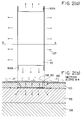
- Fig. 1 is a schematic sectional view of the configurations of a liquid flow passage and electrothermal transducer elements of a liquid jet head in accordance with the present invention, in which the liquid flow passage is seen from the side opposite from the electrothermal transducer elements.
- a liquid flow passage 1 communicates with a liquid chamber 2, and a meniscus 3 is formed in the liquid flow passage (nozzle) in the vicinity of an orifice (ejection opening) by a capillary force.
- At least two electrothermal transducer elements may be provided in the nozzle.
- Selecting electrodes i.e., wiring electrodes 8 and 9 and a common electrode 10 in the form of layers are formed on a heating resistor layer. Regions between these electrodes are defined as heating regions of two electrothermal transducer elements 4 and 6.
- Electric signals are selectively applied to the selecting electrodes 8 and 9 to generate heat in the heating regions of the electrothermal transducer elements independently or simultaneously.
- the distances from the ejection opening to centroids (C A , C B ) of the heating regions of the electrothermal transducer elements are set so as to be equal or nearly equal to each other.
- the difference between these distances is 3 ⁇ m or less. If the difference is larger than this value, a need for considering the difference between ejection amounts due to the difference between the distances between the heating regions and the ejection opening arises.
- the two electrothermal transducer elements disposed in one flow passage (nozzle) differ from each other in heating area.
- the heating region of the smaller electrothermal transducer element 4 has an area Sh A while the heating region of the larger electrothermal transducer element 6 has an area Sh B .
- the selecting wiring electrodes 8 and 9 are connected to the electrothermal transducer elements 4 and 6, respectively, and the common wiring electrode 10 is connected to the same on the side opposite from the selecting wiring electrodes 8 and 9.
- a switching means such as a transistor is connected to the ends of the wiring electrodes 8 and 9 remote from the electrothermal transducer elements 4 and 6. The switching means selectively drives the electrothermal transducer elements 4 and 6 to eject ink contained in the nozzle.
- the head was designed by considering the fact that bubble generating regions 5 and 7 (in the areas indicated by the broken line) through which bubbles are generated in ink and non-bubble-generating regions through which no bubbles are generated in ink exist in the heating regions of the electrothermal transducer elements because of a heat distribution as described above. If such ratios are selected, each of different required amounts of ink can be ejected stably.
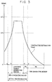
- the bubble generating regions existing in the electrothermal transducer elements will be described briefly with reference to Fig. 2.
- the film structure of the electrothermal transducer elements used in accordance with the present invention is such that a heat accumulating layer 105 formed of an insulating material such as SiO 2 is formed on a silicon substrate 106 having a thickness of about 500 to 600 ⁇ m, and a resistor layer 101 is formed and patterned on the heat accumulating layer 105.
- a protective layer 103 formed of an insulating material such as SiO 2 or SiN and a cavitation proofing layer 120 which absorbs impulse waves caused by growth and collapse of a bubble are formed over the resistor layer 101.
- a voltage is applied to the resistor layer 101 through wiring electrodes 102A and 102B voltages to cause a current for heating.
- Heat generated in the resistor layer escapes in the direction of superposition of the films at a central portion of the electrothermal transducer element, but also escapes in the film spreading direction at each end of the electrothermal transducer element.
- the temperature is lower at each end of the electrothermal transducer element than at the central portion.
- the electrothermal transducer element has, along the line A - A, a surface temperature distribution such as represented by a temperature distribution Temp A shown in Fig. 3. It can be understood from Fig.
- ⁇ T1 represents a lower limit temperature at which a bubble can be formed in ink on the electrothermal transducer element
- ⁇ T2 represents a temperature at which the electrothermal transducer element is excessively heated and damaged by thermal stress or the like so that its life becomes very short.
- a head was constructed in substantially the same manner as the head of Example 1.
- a head was constructed in substantially the same manner as the head of Example 1.
- suitable drive voltages are about 10 V and 33 V if the drive pulse width is constant. Driving by such voltages is disadvantageous in terms of drive energy efficiency, and it is difficult to stably maintain the desired amounts of ejection by the electrothermal transducer elements.
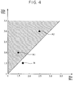
- Fig. 4 is a graph of the ratio of the areas of the heating regions of each of the electrothermal transducer elements of the above-described examples (Example 1: A1, Example 2: A2) and the comparative example (B) (on the abscissa) with respect to the ratio of the ejection amounts (on the ordinate).
- Example 1 designates the case where the area ratio and the ejection amount ratio are equal to each other.
- the area ratio-ejection amount ratio relationship of each of Example 1(A1) and Example 2(A2) is indicated in the hatched area defined in accordance with the present invention.
- the desired amount of liquid can be stably ejected by each electrothermal transducer element, and the ejection characteristics are advantageous in terms of drive energy efficiency.
- the area ratio-ejection amount ratio relationship of the comparative example (B) is out of the area in accordance with the present invention.
- the ejection characteristics are disadvantageous in terms of drive energy efficiency.
- the condition of the present invention is particularly effective when the distances of the centroid positions of the electrothermal transducer elements, i.e., the distances OC A and OC B of the centroids C A and C B of the electrothermal transducer elements 4 and 5 shown in Fig. 1 from the orifice surface are approximately equal to each other (the error is not larger than a manufacturing variation of about 3 ⁇ m). Also, it is more desirable that the materials, the film thicknesses and drive conditions of the electrothermal transducer elements are substantially equal to each other.
- the width W A (d) of the above-described non-bubble-generating region of the electrothermal transducer element is about 3 to 5 ⁇ m.
- the width W A (d) varies depending upon the structure and materials of the films and drive conditions. It is necessary to consider the possibility of the width W A (d) ranging from about 0.1 to 10 ⁇ m under some condition. An optimal condition of Vd B /Vd A > Sh B /Sh A is obtained by considering these conditions, as described below.
- Vd B /Vd A ((Wh B - 2W A ) ⁇ (Lh B - 2W A ))/((Wh A - 2W A ) ⁇ (Lh A - 2W A )) is established in theory.
- Vd B /Vd A (Sh B - L B ⁇ W A )/(Sh A - L A ⁇ W A ) is established in theory where L A and L B are the lengths of the peripheries (indicated by the broken lines in Fig. 1) of the regions defined inside the electrothermal transducer elements 4 and 5 at a distance of W A /2 from the peripheries of the same. If the electrothermal transducer elements are designed under this design condition, the ratio of the desired ejection amounts can easily be set. Actually, the electrothermal transducer elements are ordinarily designed so as to be approximately equal in length in order to equalize conditions of driving them.
- the adjustment of the overall ejection amount and so on may be performed in a later step of setting the orifice area or positioning the electrothermal transducer elements with respect to the nozzle, as mentioned above, thus facilitating designing and manufacturing.
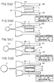
- Ejection nozzle 104 interposed between nozzle walls 109 is filled with ink as shown in Fig. 5(a) is filled with ink.
- a drive signal is applied to each of the electrothermal transducer elements 4 and 6 to heat ink so that a bubble is generated in ink.
- Ink is ejected through orifice 40 by a pressure caused by the growth of the bubble.
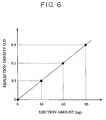
- Fig. 5(b) shows a state in which the smaller electrothermal transducer element 4 is heated to generate a smaller bubble 119, whereby a smaller droplet 114 is ejected. It is assumed here that the ejection amount at this time is 30 ng.
- FIG. 5(c) shows a state in which the larger electrothermal transducer element 6 is heated to generate a larger bubble 112, whereby a larger droplet 115 is ejected.
- the larger electrothermal transducer element 6 is designed to have an effective bubble generating area twice that of the smaller electrothermal transducer element 4, the amount of ejection by the larger electrothermal transducer element 6 is about 60 ng since the ejection amount is proportional to the effective bubble generating area.
- Fig. 5(d) shows a state in which both the electrothermal transducer elements are heated to generate bubbles. In this event, the total ejection amount is the sum of the amounts of ejection by the two electrothermal transducer elements, i.e., 90 ng.
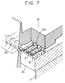
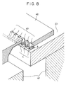
- FIGs. 7 and 8 show examples of the construction of nozzles and portions round the nozzles, i.e., an edge shoe type construction and a side shoe type construction.
- Ink in each of ejection nozzles 104 is heated by one or both of electrothermal transducer elements 4 and 6 to form a bubble, thereby ejecting ink through orifice 40 which is open in a lateral or upward direction.
- An element substrate 23 is bonded to a base plate 41.
- Nozzle walls 109 are provided on a ceiling plate 42.
- Fig. 9 shows an ink jet head cartridge in which the ink jet head (liquid jet head) of the present invention and an ink container containing ink to be supplied to the ink jet head are separably connected to each other.
- Ink is injected into the ink tank constituting this ink jet head cartridge in a manner described below.
- An ink supply pipe or the like is connected to the ink container to form an ink introduction passage, and ink is injected into the ink container through this ink introduction passage.
- an ink supply port of the ink container a supply port to the ink jet head, an atmospheric air opening, a hole formed in a wall portion of the ink container or the like may be used.
- Fig. 10 shows an example of an ink jet recording apparatus IJRA in which the ink jet recording head arranged as described above is mounted.
- the ink jet recording apparatus IJRA has a lead screw 2040 which rotates by being linked to the rotation of a drive motor 2010 in the normal and reverse directions through driving force transmission gears 2020 and 2030.
- a carriage HC which supports an ink jet cartridge IJC in which the ink jet recording head and an ink tank are combined integrally with each other is supported by a carriage shaft 2050 and a lead screw 2040, has a pin (not shown) engaging with a helical groove 2041 of the lead screw 2040, and moves reciprocatingly in the directions of arrows a and b.
- a paper retaining plate 2060 presses a paper sheet P against a platen roller 2070 through a carriage traveling width.
- the platen roller 2070 constitutes a transport means for transporting paper P, i.e., a recording medium.
- Photocouplers 2080 and 2090 operate as home position detection means to confirm the existence of a lever 2100 of the carriage HC in their region to perform an operation of changing the direction of rotation of the motor 2010 or the like.
- a member 2120 supports a cap member 2110 for capping a front side of the recording head.
- a drawing means 2130 for evacuating the interior of the cap is used for drawing recovery of the recording head through an internal cap opening.
- a cleaning blade 2140 for cleaning the end surface of the recording head is provided on a member 2150 which is movable forward and rearward.
- the cleaning blade 2140 and the member 2150 are supported on a main body supporting plate 2160. Needless to say, any other well-known cleaning blade can be applied to this apparatus in place of the cleaning blade 2140.
- a lever 2170 is used to start drawing for drawing recovery. The lever 2170 moves with the movement of a cam 2180 engaging with the carriage HC, and the transmission of the driving force from the drive motor 2010 is controlled by a well-known transmission means such as a clutch.
- the desired processing can be started at the corresponding position through the operation of the lead screw 2040 when the carriage HC moves into a region on the home position side. Any of these kinds of functions can be applied to this apparatus if the desired operation can be performed by a well-known timing.
- This apparatus also has a drive signal supply means for supplying a signal for driving the heating resistors, i.e., electrothermal transducers of the ink jet head of the present invention.
- the ink jet head of the present invention has been described with respect to two electrothermal transducer elements in one nozzle. Needless to say, even if three or more electrothermal transducer elements are provided in one nozzle, the relationship between the ejection amount ratio and the area ratio in accordance with the above-described relational equation is established with respect to each of the electrothermal transducer elements.
- the ratio of the amount of ejection by a plurality of electrothermal transducer elements and the ratio of the areas of the electrothermal transducer elements are set in a suitable relationship to obtain desired ejection amounts, thereby enabling high-linearity gradation control.
Landscapes
- Particle Formation And Scattering Control In Inkjet Printers (AREA)
- Ink Jet (AREA)
Claims (14)
- Flüssigkeitsstrahlkopf miteinem Flüssigkeitsdurchtritt (1) mit einer Ausspritzöffnung zum Ausspritzen einer Flüssigkeit undeiner Vielzahl an elektrothermischen Wandlerelementen (4, 6), die in dem Flüssigkeitsdurchtritt vorgesehen sind, wobei die Vielzahl an elektrothermischen Wandlerelementen unter gleichen oder annähernd gleichen Abständen von der Ausspritzöffnung angeordnet sind,
dadurch gekennzeichnet, daßdie Flächen von zwei der Vielzahl an elektrothermischen Wandlerelementen (4, 6) ShB und ShA (ShB > ShA) betragen und die durch die beiden elektrothermischen Wandlerelemente (4, 6) ausgespritzten Mengen an Tinte VdB und VdA betragen und - Flüssigkeitsstrahlkopf gemäß Anspruch 1, wobeidie Längen (LhB, LhA) der beiden elektrothermischen Wandlerelemente (4, 6) einander annähernd gleich sind und, wenn die Breiten der beiden elektrothermischen Wandlerelemente WhB und WhA betragen und die Breite eines nicht Blasen erzeugenden Bereiches WA trägt, VdB/VdA im wesentlichen
- Flüssigkeitsstrahlkopf gemäß Anspruch 1, wobeiwenn die Breiten der beiden elektrothermischen Wandlerelemente (4, 6) WhB und WhA betragen, die Länge der beiden elektrothermischen Wandlerelemente LhB und LhA betragen und die Breite eines nicht Blasen erzeugenden Bereiches WA beträgt, VdB/VdA im wesentlichen
- Flüssigkeitstrahlkopf gemäß Anspruch 1, wobeider Unterschied zwischen den Entfernungen (OCA, OCB) zwischen der Position, an der die Ausspritzöffnung ausgebildet ist, und den Flächenschwerpunkten (CA, CB) der elektrothermischen Wandlerelemente (4, 5), die so vorgesehen sind, daß sie dem Flüssigkeitsdurchtritt zugewandt sind, nicht größer als drei µm beträgt.
- Flüssigkeitsstrahlkopf gemäß Anspruch 1, wobeidie Anzahl an elektrothermischen Wandlerelementen (4, 6), die so vorgesehen sind, daß sie dem Flüssigkeitsdurchtritt (1) zugewandt sind, 2 beträgt.
- Flüssigkeitsstrahlkopf gemäß Anspruch 1, wobeidie Flüssigkeit Tinte ist.
- Kopfkartusche (IJC) miteinem Flüssigkeitsstrahlkopf gemäß Anspruch 1 undeinem Flüssigkeitsbehälter zum Aufbewahren einer zu dem Flüssigkeitsstrahlkopf zu liefernden Flüssigkeit.
- Kopfkartusche gemäß Anspruch 7, wobeider Flüssigekeitsstrahlkopf und der Flüssigkeitsbehälter aneinander abnehmbar angebracht sind.
- Kopfkartusche gemäß Anspruch 7, wobeidie Flüssigkeit Tinte ist.
- Flüssigkeitsstrahlgerät (IJRA) miteinem Flüssigkeitsstrahlkopf gemäß Anspruch 1 undeiner Transporteinrichtung (2070) zum Transportieren eines Aufzeichnungsmediums.
- Flüssigkeitsstrahlgerät (IJRA) miteinem Flüssigkeitsstrahlkopf gemäß Anspruch 1 undeine Antriebssignalliefereinrichtung zum Antreiben des Flüssigkeitsstrahlkopfes.
- Flüssigkeitsstrahlverfahren mit den folgenden Schritten:Verwenden eines Flüssigkeitsstrahlkopfes mit einem Flüssigkeitsdurchtritt mit einer Ausspritzöffnung zum Ausspritzen einer Flüssigkeit und einer Vielzahl an elektrothermischen Wandlerelementen, die an dem Flüssigkeitsdurchtritt vorgesehen sind, wobei die Vielzahl an elektrothermischen Wandlerelementen bei gleichen oder annähernd gleichen Abständen von der Ausspritzöffnung angeordnet ist, wobei zwei der Vielzahl an elektrothermischen Wandlerelementen Flächen Sh1 und Sh2 haben, undAufbringen von Antriebssignalen auf die elektrothermischen Wandlerelemente (4, 6), so daß das Sh1 entsprechende elektrothermische Wandlerelement eine Menge Vd1 an Flüssigkeit ausspritzt, während das Sh2 entsprechende elektrothermische Wandlerelement eine Menge Vd2 an Flüssigkeit ausspritzt,
dadurch gekennzeichnet, daßdie Flächen ShB, ShA und die Mengen an Flüssigkeit VdB und VdA ShB > ShA und - Verfahren zum Einspritzen einer Flüssigkeit in einen Flüssigkeitsbehälter mit den folgenden Schritten:Ausbilden eines Flüssigkeitseinführdurchtrittes zum Einführen einer Flüssigkeit in einen Flüssigkeitsbehälter, der eine Kopfkartusche gemäß Anspruch 7 bildet, undEinspritzen der Flüssigkeit in den Flüssigkeitsbehälter durch den Flüssigkeitseinleitdurchtritt.
- Verfahren gemäß Anspruch 13, wobeidie Flüssigkeit Tinte ist.
Applications Claiming Priority (6)
| Application Number | Priority Date | Filing Date | Title |
|---|---|---|---|
| JP25524894 | 1994-10-20 | ||
| JP255248/94 | 1994-10-20 | ||
| JP25524894 | 1994-10-20 | ||
| JP25634795 | 1995-10-03 | ||
| JP25634795A JP3715696B2 (ja) | 1994-10-20 | 1995-10-03 | 液体吐出ヘッド、ヘッドカートリッジおよび液体吐出装置 |
| JP256347/95 | 1995-10-03 |
Publications (3)
| Publication Number | Publication Date |
|---|---|
| EP0707964A2 EP0707964A2 (de) | 1996-04-24 |
| EP0707964A3 EP0707964A3 (de) | 1997-03-19 |
| EP0707964B1 true EP0707964B1 (de) | 1999-09-29 |
Family
ID=26542097
Family Applications (1)
| Application Number | Title | Priority Date | Filing Date |
|---|---|---|---|
| EP95116588A Expired - Lifetime EP0707964B1 (de) | 1994-10-20 | 1995-10-20 | Glüssigkeitsstrahlkopf, Kopfkassette, Flüssigkeitsstrahlapparat, Flüssigkeitsstrahlverfahren und Tintenstrahlverfahren |
Country Status (4)
| Country | Link |
|---|---|
| US (1) | US5754201A (de) |
| EP (1) | EP0707964B1 (de) |
| JP (1) | JP3715696B2 (de) |
| DE (1) | DE69512493T2 (de) |
Families Citing this family (27)
| Publication number | Priority date | Publication date | Assignee | Title |
|---|---|---|---|---|
| JPH08118641A (ja) | 1994-10-20 | 1996-05-14 | Canon Inc | インクジェットヘッド、インクジェットヘッドカートリッジ、インクジェット装置およびインクが再注入されたインクジェットヘッドカートリッジ用インク容器 |
| JPH08332727A (ja) * | 1995-06-06 | 1996-12-17 | Canon Inc | インクジェット記録ヘッド及びインクジェット記録装置 |
| JP3559647B2 (ja) * | 1996-04-22 | 2004-09-02 | キヤノン株式会社 | インクジェット記録ヘッド、インクジェットヘッドカートリッジ及びインクジェット記録装置 |
| EP0811489B1 (de) * | 1996-06-07 | 2002-05-22 | Canon Kabushiki Kaisha | Verfahren zum Ausstossen von Flüssigkeit, Flüssigkeitsausstosskopf, Flüssigkeitsausstosskopfkassette und Vorrichtung zum Ausstossen von Flüssigkeit |
| US6062678A (en) * | 1996-06-26 | 2000-05-16 | Canon Kabushiki Kaisha | Ink-jet recording head with a particular arrangement of thermoelectric transducers and discharge openings |
| JPH1071730A (ja) * | 1996-06-27 | 1998-03-17 | Canon Inc | インクジェット記録方法及びその装置とインクジェット記録ヘッド |
| JP3337912B2 (ja) * | 1996-06-28 | 2002-10-28 | キヤノン株式会社 | インクジェットヘッドの駆動方法及びこれを実行するインクジェット装置 |
| JP3554138B2 (ja) * | 1996-06-28 | 2004-08-18 | キヤノン株式会社 | インクジェット記録方法、インクジェット記録ヘッド及びインクジェット記録装置 |
| US6169556B1 (en) * | 1996-06-28 | 2001-01-02 | Canon Kabushiki Kaisha | Method for driving a recording head having a plurality of heaters arranged in each nozzle |
| US6020905A (en) * | 1997-01-24 | 2000-02-01 | Lexmark International, Inc. | Ink jet printhead for drop size modulation |
| JP3501619B2 (ja) * | 1997-05-07 | 2004-03-02 | キヤノン株式会社 | インクジェット記録ヘッド |
| JP3625357B2 (ja) | 1997-06-06 | 2005-03-02 | キヤノン株式会社 | 液体輸送方法および液体輸送装置 |
| JP3639698B2 (ja) * | 1997-07-31 | 2005-04-20 | キヤノン株式会社 | 液体吐出ヘッド、ヘッドカートリッジ、液体吐出記録装置、および液体吐出ヘッドの製造方法 |
| US6375309B1 (en) | 1997-07-31 | 2002-04-23 | Canon Kabushiki Kaisha | Liquid discharge apparatus and method for sequentially driving multiple electrothermal converting members |
| JP3592096B2 (ja) * | 1997-09-11 | 2004-11-24 | キヤノン株式会社 | インクジェット記録ヘッド及びインクジェット記録装置 |
| JPH11227210A (ja) | 1997-12-05 | 1999-08-24 | Canon Inc | 液体吐出ヘッド、該ヘッドの製造方法、ヘッドカートリッジおよび液体吐出装置 |
| US6471337B1 (en) * | 1998-10-27 | 2002-10-29 | Canon Kabushiki Kaisha | Ink-jet printing apparatus, ejection recovery method for ink-jet printing apparatus, and fabrication method of ink-jet printing head |
| JP3697089B2 (ja) * | 1998-11-04 | 2005-09-21 | キヤノン株式会社 | インクジェットヘッド用基体、インクジェットヘッド、インクジェットカートリッジおよびインクジェット記録装置 |
| EP1080906A3 (de) * | 1999-09-03 | 2002-04-24 | Canon Kabushiki Kaisha | Flüssigkeitsausstosskopf, Flüssigkeitsausstossverfahren, und Flüssigkeitsausstossvorrichtung |
| US7222927B2 (en) * | 2002-12-12 | 2007-05-29 | Sony Corporation | Liquid discharge device and liquid discharge method |
| JP3770252B2 (ja) * | 2003-02-27 | 2006-04-26 | ソニー株式会社 | 液体吐出装置及び液体吐出方法 |
| US7905577B2 (en) * | 2006-12-15 | 2011-03-15 | Canon Kabushiki Kaisha | Printhead substrate having electrothermal transducers arranged at high density, printhead, and printing apparatus |
| US8231195B2 (en) * | 2008-05-08 | 2012-07-31 | Canon Kabushiki Kaisha | Print element substrate, printhead, and printing apparatus |
| ATE547249T1 (de) | 2008-05-08 | 2012-03-15 | Canon Kk | Druckelementsubstrat, druckkopf und druckvorrichtung |
| US8167411B2 (en) * | 2008-05-08 | 2012-05-01 | Canon Kabushiki Kaisha | Print element substrate, inkjet printhead, and printing apparatus |
| PL2910380T3 (pl) * | 2010-07-23 | 2018-06-29 | Hewlett-Packard Development Company, L.P. | Zespół opornika grzewczego wyrzucający płyn |
| CN104772983B (zh) * | 2010-07-23 | 2017-04-12 | 惠普发展公司,有限责任合伙企业 | 热电阻器流体喷射组件 |
Family Cites Families (17)
| Publication number | Priority date | Publication date | Assignee | Title |
|---|---|---|---|---|
| DE2945658A1 (de) * | 1978-11-14 | 1980-05-29 | Canon Kk | Fluessigkeitsstrahl-aufzeichnungsverfahren |
| JPS55132259A (en) * | 1979-04-02 | 1980-10-14 | Canon Inc | Liquid jet recording method |
| US4463359A (en) * | 1979-04-02 | 1984-07-31 | Canon Kabushiki Kaisha | Droplet generating method and apparatus thereof |
| US4558333A (en) * | 1981-07-09 | 1985-12-10 | Canon Kabushiki Kaisha | Liquid jet recording head |
| US4611219A (en) * | 1981-12-29 | 1986-09-09 | Canon Kabushiki Kaisha | Liquid-jetting head |
| JPS59123672A (ja) * | 1982-12-28 | 1984-07-17 | Canon Inc | 液体噴射ヘッド及び液体噴射記録装置 |
| US4646110A (en) * | 1982-12-29 | 1987-02-24 | Canon Kabushiki Kaisha | Liquid injection recording apparatus |
| EP0124312A3 (de) * | 1983-04-29 | 1985-08-28 | Hewlett-Packard Company | Widerstandsanordnungen für thermische Tintenstrahldrucker |
| US4881318A (en) * | 1984-06-11 | 1989-11-21 | Canon Kabushiki Kaisha | Method of manufacturing a liquid jet recording head |
| JPS62261452A (ja) * | 1986-05-09 | 1987-11-13 | Canon Inc | 多値化記録方式 |
| JP2793593B2 (ja) * | 1988-03-16 | 1998-09-03 | 株式会社リコー | 液体噴射記録ヘッド |
| US5175565A (en) * | 1988-07-26 | 1992-12-29 | Canon Kabushiki Kaisha | Ink jet substrate including plural temperature sensors and heaters |
| EP0385757B1 (de) * | 1989-03-01 | 1995-02-01 | Canon Kabushiki Kaisha | Substrat für thermischen Aufzeichnungskopf und thermischer Aufzeichnungskopf unter Verwendung dieses Substrats |
| JPH02239940A (ja) * | 1989-03-14 | 1990-09-21 | Nec Corp | インクジェットヘッド |
| ATE148043T1 (de) * | 1989-09-18 | 1997-02-15 | Canon Kk | Flüssigkeitsstrahlaufzeichnungskopf und flüssigkeitsstrahlaufzeichnungsgerät, welches diesen aufweist |
| CA2108304C (en) * | 1992-10-15 | 1999-08-10 | Hiroyuki Ishinaga | Ink jet recording apparatus |
| ATE152399T1 (de) * | 1993-02-26 | 1997-05-15 | Canon Kk | Tintenstrahldruckkopf, tintenstrahlkopf-kartusche und druckgerät |
-
1995
- 1995-10-03 JP JP25634795A patent/JP3715696B2/ja not_active Expired - Fee Related
- 1995-10-18 US US08/544,597 patent/US5754201A/en not_active Expired - Lifetime
- 1995-10-20 DE DE69512493T patent/DE69512493T2/de not_active Expired - Lifetime
- 1995-10-20 EP EP95116588A patent/EP0707964B1/de not_active Expired - Lifetime
Also Published As
| Publication number | Publication date |
|---|---|
| EP0707964A3 (de) | 1997-03-19 |
| DE69512493T2 (de) | 2000-04-13 |
| US5754201A (en) | 1998-05-19 |
| JPH08169116A (ja) | 1996-07-02 |
| JP3715696B2 (ja) | 2005-11-09 |
| DE69512493D1 (de) | 1999-11-04 |
| EP0707964A2 (de) | 1996-04-24 |
Similar Documents
| Publication | Publication Date | Title |
|---|---|---|
| EP0707964B1 (de) | Glüssigkeitsstrahlkopf, Kopfkassette, Flüssigkeitsstrahlapparat, Flüssigkeitsstrahlverfahren und Tintenstrahlverfahren | |
| EP0707963B1 (de) | Tintenstrahlkopf, Tintenstrahlkopfkassette und Tintenstrahlapparat | |
| EP0684134B1 (de) | Tintenstrahlkopf, Tintenstrahlgerät und Verfahren zur Füllen einer Puffenkammer mit Blasen | |
| JP3950730B2 (ja) | インクジェット記録ヘッドおよびインク吐出方法 | |
| JP4574385B2 (ja) | インクジェット記録ヘッドおよび記録装置 | |
| KR20000035178A (ko) | 잉크 제트 헤드용 기판, 잉크 제트 헤드, 잉크 제트카트리지 및 잉크 제트 기록 장치 | |
| EP1033249B1 (de) | Verfahren zum Ansteuern eines Tintenstrahldruckkopfes und Aufzeichnungsvorrichtung zum Ausführen des Verfahrens | |
| JP2004001490A (ja) | インクジェットヘッド | |
| EP1092544B1 (de) | Tintenstrahldruckvorrichtung und Tintenstrahldruckverfahren | |
| US20070052759A1 (en) | Inkjet printhead and method of manufacturing the same | |
| EP0593051B1 (de) | Tintanstrahlaufzeichnungsgerät | |
| EP1419887B1 (de) | Flüssigkeitsausstossverfahren und -Vorrichtung | |
| US6145962A (en) | Method and apparatus for printing | |
| JP4208399B2 (ja) | インクジェット記録装置、及びインクジェット記録方法 | |
| JPH03234636A (ja) | インクジェット記録装置 | |
| JP2002079665A (ja) | インクジェット式記録装置及び記録方法 | |
| JP3025584B2 (ja) | インクジェット記録装置およびインクカセット | |
| US7946688B2 (en) | Recording head and recording apparatus | |
| JPH0441242A (ja) | インクジェット記録装置 | |
| JP2882487B2 (ja) | インクジェット記録ヘッド及び該記録ヘッドを備えたインクジェット記録装置 | |
| JP3544061B2 (ja) | インクジェット記録ヘッドおよびインクジェット記録装置 | |
| JPH0412861A (ja) | インクジェット記録ヘッド及び該記録ヘッドを備えたインクジェット記録装置 | |
| JPH03295662A (ja) | インクジェット記録装置 | |
| JP2000006415A (ja) | 液体吐出ヘッドおよびヘッドカートリッジならびに画像形成装置 | |
| JPH0412860A (ja) | インクジェット記録ヘッド用基体、該基体を有するインクジェット記録ヘッド及び該記録ヘッドを備えたインクジェット記録装置 |
Legal Events
| Date | Code | Title | Description |
|---|---|---|---|
| PUAI | Public reference made under article 153(3) epc to a published international application that has entered the european phase |
Free format text: ORIGINAL CODE: 0009012 |
|
| AK | Designated contracting states |
Kind code of ref document: A2 Designated state(s): DE FR GB IT |
|
| PUAL | Search report despatched |
Free format text: ORIGINAL CODE: 0009013 |
|
| AK | Designated contracting states |
Kind code of ref document: A3 Designated state(s): DE FR GB IT |
|
| 17P | Request for examination filed |
Effective date: 19970805 |
|
| GRAG | Despatch of communication of intention to grant |
Free format text: ORIGINAL CODE: EPIDOS AGRA |
|
| 17Q | First examination report despatched |
Effective date: 19981106 |
|
| GRAG | Despatch of communication of intention to grant |
Free format text: ORIGINAL CODE: EPIDOS AGRA |
|
| GRAH | Despatch of communication of intention to grant a patent |
Free format text: ORIGINAL CODE: EPIDOS IGRA |
|
| GRAH | Despatch of communication of intention to grant a patent |
Free format text: ORIGINAL CODE: EPIDOS IGRA |
|
| GRAA | (expected) grant |
Free format text: ORIGINAL CODE: 0009210 |
|
| AK | Designated contracting states |
Kind code of ref document: B1 Designated state(s): DE FR GB IT |
|
| REF | Corresponds to: |
Ref document number: 69512493 Country of ref document: DE Date of ref document: 19991104 |
|
| ET | Fr: translation filed | ||
| ITF | It: translation for a ep patent filed |
Owner name: SOCIETA' ITALIANA BREVETTI S.P.A. |
|
| PLBE | No opposition filed within time limit |
Free format text: ORIGINAL CODE: 0009261 |
|
| STAA | Information on the status of an ep patent application or granted ep patent |
Free format text: STATUS: NO OPPOSITION FILED WITHIN TIME LIMIT |
|
| 26N | No opposition filed | ||
| REG | Reference to a national code |
Ref country code: GB Ref legal event code: IF02 |
|
| PGFP | Annual fee paid to national office [announced via postgrant information from national office to epo] |
Ref country code: IT Payment date: 20081020 Year of fee payment: 14 |
|
| PGFP | Annual fee paid to national office [announced via postgrant information from national office to epo] |
Ref country code: FR Payment date: 20081024 Year of fee payment: 14 |
|
| REG | Reference to a national code |
Ref country code: FR Ref legal event code: ST Effective date: 20100630 |
|
| PG25 | Lapsed in a contracting state [announced via postgrant information from national office to epo] |
Ref country code: FR Free format text: LAPSE BECAUSE OF NON-PAYMENT OF DUE FEES Effective date: 20091102 |
|
| PGFP | Annual fee paid to national office [announced via postgrant information from national office to epo] |
Ref country code: DE Payment date: 20101031 Year of fee payment: 16 |
|
| PG25 | Lapsed in a contracting state [announced via postgrant information from national office to epo] |
Ref country code: IT Free format text: LAPSE BECAUSE OF NON-PAYMENT OF DUE FEES Effective date: 20091020 |
|
| PGFP | Annual fee paid to national office [announced via postgrant information from national office to epo] |
Ref country code: GB Payment date: 20101019 Year of fee payment: 16 |
|
| GBPC | Gb: european patent ceased through non-payment of renewal fee |
Effective date: 20121020 |
|
| PG25 | Lapsed in a contracting state [announced via postgrant information from national office to epo] |
Ref country code: DE Free format text: LAPSE BECAUSE OF NON-PAYMENT OF DUE FEES Effective date: 20130501 Ref country code: GB Free format text: LAPSE BECAUSE OF NON-PAYMENT OF DUE FEES Effective date: 20121020 |
|
| REG | Reference to a national code |
Ref country code: DE Ref legal event code: R119 Ref document number: 69512493 Country of ref document: DE Effective date: 20130501 |