EP0705950B1 - Hohlraumboden - Google Patents
Hohlraumboden Download PDFInfo
- Publication number
- EP0705950B1 EP0705950B1 EP95102203A EP95102203A EP0705950B1 EP 0705950 B1 EP0705950 B1 EP 0705950B1 EP 95102203 A EP95102203 A EP 95102203A EP 95102203 A EP95102203 A EP 95102203A EP 0705950 B1 EP0705950 B1 EP 0705950B1
- Authority
- EP
- European Patent Office
- Prior art keywords
- depressions
- floor according
- false floor
- floor
- filler
- Prior art date
- Legal status (The legal status is an assumption and is not a legal conclusion. Google has not performed a legal analysis and makes no representation as to the accuracy of the status listed.)
- Expired - Lifetime
Links
- 239000000463 material Substances 0.000 claims abstract description 14
- 229920005830 Polyurethane Foam Polymers 0.000 claims abstract description 4
- 239000007799 cork Substances 0.000 claims abstract description 4
- 230000000717 retained effect Effects 0.000 claims abstract 2
- 239000000945 filler Substances 0.000 claims description 24
- 239000011324 bead Substances 0.000 claims description 5
- 239000006260 foam Substances 0.000 claims description 5
- 239000011148 porous material Substances 0.000 claims description 3
- 239000000853 adhesive Substances 0.000 claims description 2
- 230000001070 adhesive effect Effects 0.000 claims description 2
- 229920000642 polymer Polymers 0.000 claims 1
- 239000000126 substance Substances 0.000 claims 1
- 239000011796 hollow space material Substances 0.000 abstract 1
- 230000002093 peripheral effect Effects 0.000 abstract 1
- 239000002861 polymer material Substances 0.000 abstract 1
- 239000011496 polyurethane foam Substances 0.000 abstract 1
- 230000002787 reinforcement Effects 0.000 abstract 1
- 230000003584 silencer Effects 0.000 description 6
- 238000009413 insulation Methods 0.000 description 5
- 238000004519 manufacturing process Methods 0.000 description 4
- 238000001035 drying Methods 0.000 description 3
- 229920001971 elastomer Polymers 0.000 description 2
- 239000011888 foil Substances 0.000 description 2
- 238000009825 accumulation Methods 0.000 description 1
- 230000005540 biological transmission Effects 0.000 description 1
- 210000000078 claw Anatomy 0.000 description 1
- 230000000694 effects Effects 0.000 description 1
- 238000002474 experimental method Methods 0.000 description 1
- 238000009408 flooring Methods 0.000 description 1
- 230000009969 flowable effect Effects 0.000 description 1
- 238000009415 formwork Methods 0.000 description 1
- 238000009434 installation Methods 0.000 description 1
- 239000007788 liquid Substances 0.000 description 1
- 230000000149 penetrating effect Effects 0.000 description 1
- 229920003023 plastic Polymers 0.000 description 1
- 239000004033 plastic Substances 0.000 description 1
- 239000002689 soil Substances 0.000 description 1
- 238000007711 solidification Methods 0.000 description 1
- 230000008023 solidification Effects 0.000 description 1
- 238000003856 thermoforming Methods 0.000 description 1
Images


Classifications
-
- E—FIXED CONSTRUCTIONS
- E04—BUILDING
- E04F—FINISHING WORK ON BUILDINGS, e.g. STAIRS, FLOORS
- E04F15/00—Flooring
- E04F15/02—Flooring or floor layers composed of a number of similar elements
- E04F15/024—Sectional false floors, e.g. computer floors
- E04F15/02405—Floor panels
- E04F15/02417—Floor panels made of box-like elements
- E04F15/02423—Floor panels made of box-like elements filled with core material
- E04F15/02429—Floor panels made of box-like elements filled with core material the core material hardening after application
Definitions
- the invention relates to a cavity floor, comprising a profiled Intermediate floor arranged between an upper and a lower floor and is plate-shaped, the intermediate bottom pot-shaped Has depressions through substantially flat edge areas connected together and filled with a sound-absorbing filler and wherein on the side of the bottoms facing away from the depressions Wells each a foot muffler is arranged, which the floor in essentially completely covered
- Such a cavity floor is known from DE-U-93 18 517.
- the cavity floor is designed to accommodate underfloor installations and is manufactured using the press or thermoforming process.
- the sound-absorbing filler which consists of a closed-cell foam body with a density of 20 to 70 kg / m 3 , provides impact sound insulation.
- the cup-shaped depressions are circular in cross-section.
- Raised floor has a profiled and covered with screed Floor film with truncated cone-shaped feet, the Floor film adjusts unevenness of the sub-floor and is accessible.
- the Floor film forms a formwork for the screed material to be applied, the forms the topsoil.
- the floor film is plate-shaped and as thin as possible formed so that adjacent foil plates loose at their edges can be laid one on top of the other without steps in the screed layer.
- the invention has for its object a cavity floor of the known Kind to develop in such a way that internal tensions in the screed, the Forms topsoil and avoid that the screed is shorter Has drying time.
- the raised floor is also said to be a good one Have impact sound insulation and in manufacturing technology and economical Regarding be simple and inexpensive to manufacture.
- the The muffler has the shape of a regular hexagon.
- the depressions in the intermediate floor do not form the screed that forms the top floor are filled out, but with a sound-absorbing filler, the Screed drying time by avoiding material accumulation in the The area of the depressions is significantly shortened and internal tensions within the Avoid screed reliably.
- a transmission of annoying impact sound from The top floor on the underbody is covered with the soundproofing Filler-filled depressions significantly reduced.
- the sub-floor mostly consists of concrete, on which the Intermediate floor liquid screed material applied to produce the top floor becomes.
- To produce a top floor with a smooth surface is from Advantage if the mezzanine floor is accessible to the viscous if necessary To be able to smooth screed material.
- a foot muffler is arranged on each side of the bottom of the recesses.
- the impact silencer it is also an advantage that low due to the elastic flexibility of the impact silencer Unevenness in the subfloor can be bleached out.
- the arrangement of the impact silencers is a decoupling of impact or structure-borne noise reached because the flooring film only touches the screed. The whole The intermediate floor and the top floor formed by the screed are only through the impact silencers are supported on the underbody.
- the impact silencer covers the floor essentially completely, whereby the impact silencer has the shape of a regular hexagon.
- the impact silencer with its full coverage the soil is only exposed to a comparatively low surface pressure and therefore relaxation phenomena that impair impact sound insulation be avoided.
- the shape of the regular hexagon is in manufacturing technology and economic terms particularly advantageous.
- the impact silencers can be made absolutely waste-free become.
- the impact silencers are preferred on the bottom of the Recesses of the intermediate floor glued and have a thickness of at least 2, preferably from at least 5 mm. The good usage properties of the mezzanine with respect to the impact sound decoupling remain preserved unchanged throughout its useful life.
- the intermediate floor is formed by a floor film made of polymeric material, which is preferred can be produced by deep drawing.
- the filler within a recess preferably has a load capacity of at least 4000 N. This means that the floor covering is also accessible guaranteed if their thickness is less than 1 mm.
- the filler has good inherent rigidity and can therefore withstand high loads.
- the force acting on the intermediate floor is essentially determined by added the filler.
- the filler can be held in the recesses in an adhesive and / or form-fitting manner be.
- an adhesive and / or form-fitting manner be.
- the filler during curing claws with the adjacent surfaces of the floor film and thereby is held positively in its position.
- the edge areas can be used to improve their dimensional stability at least one bead, preferably at least two beads apply to each other at an angle of substantially Cut through 90 °.
- the increased Dimensional stability the laying of the intermediate floor on the sub-floor simplified.
- the filler is preferably formed by a PU foam.
- the bulk density of the filler is 50 to 120, preferably 60 to 100 kg / m 3 for most applications.
- Such a filler has a comparatively high load-bearing capacity, prevents screed from penetrating into the recesses and provides good impact sound insulation when walking on the cavity floor.
- the filler can also be formed, for example, by a one-piece rubber cork body, which is inserted into a depression and is adhesively connected to it, for example.
- the rubber cork bodies preferably consist of recycled components that are pressed together. The advantage here is that the mezzanine floor can be produced particularly economically in an economical manner.
- the depressions are each designed to match and that the ratio of the largest diameter and height 0.6 to 1.8, preferably 0.8 is up to 1.2.
- the design of the depressions shows the intermediate floor to a high degree Load capacity, with a buckling of the wells even when initiated of transverse forces, for example when walking on the intermediate floor for application of the screed is reliably avoided.
- the depressions are frustoconical and are provided with stiffening ribs that run along the entire height of the Extend depressions and are evenly distributed in the circumferential direction.
- stiffening ribs By which taper in the shape of a truncated cone towards the underbody Wells also arise compared to being substantially cylindrical trained depressions a relatively enlarged cavity for laying Connection cables and hoses.
- stiffening ribs can contribute to the material thickness of the intermediate floor specified minimum resilience can be further reduced.
- the intermediate floor can be formed by at least two separately produced individual elements be formed by each other by at least one fastening device can be determined.
- the intermediate floor is the laying of the intermediate floor and its handling is significantly simplified.
- the individual elements can have external dimensions that the Euro pallet size correspond so that an optimal transport space allocation at Truck and / or train loading is guaranteed.
- the fastening device can be formed by a push button system with at least one cup-shaped bulge of the first individual element at least one congruently shaped recess or recess of the second Individual element can be brought into engagement.
- the thickness of the inserted Material thickness of the partial area of the individual element corresponds to that Top floor is facing.
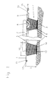
- FIGS. 1 to 4 An embodiment of the cavity floor according to the invention is shown below with reference to FIGS. 1 to 4 explained in more detail.
- Fig. 1 is a section of a cavity floor in a cross-sectional view shown.
- Fig. 2 is the intermediate floor of the cavity floor from Fig. 1 as a single part shown in cross-section, two adjacent individual elements of the intermediate floor are shown before their assembly.
- Fig. 3 the intermediate floor is in a view from the direction of the sub-floor shown.
- FIG. 4 shows two exemplary embodiments for the design of stiffening ribs shown that extend along the height of the wells and evenly are distributed in the circumferential direction.
- a section of a cavity floor is shown in a cross-sectional view.
- the cavity floor consists of an upper floor 2 designed as a screed, which is supported by an intermediate floor 1 on a sub-floor 3 made of concrete impact sound decoupled.
- the intermediate floor 1 consists of several individual elements 1.1, 1.2, which are designed as deep-drawn floor foils.
- the floor film 7 has a multiplicity of cup-shaped depressions 4, which are connected to the surface by a substantially flat edge region 5 adjoining the openings 8 of the depressions 4.
- the depressions 4 are filled with a sound-absorbing filler 6, which in this exemplary embodiment consists of a PU foam and has a density of 80 kg / m 3 .
- the foam has good inherent rigidity and can take a load of around 4000 N per well 4.
- the depressions 4 have a surface profile on the inside facing the filler 6, with which the filler 6 interlocks positively during its solidification.
- the depressions 4 are dimensioned in this embodiment such that the ratio of the largest inner diameter 10 of the depression 4 and the height 11 is one.
- the floor film 7 is provided on the side facing the sub-floor 3 with impact mufflers 14 which are adhesively connected to the floors 13 of the depressions 4.
- the plate-shaped impact silencers 14 consist of a closed-cell plastic body and cover the floor 13 essentially along its entire extent.
- the filler 6 within the depressions 4 extends into the area of the openings 8 of the depressions 4 and is flush with the edge areas 5.
- the reference number 9 denotes beads in the edge region 5, which are provided to improve the dimensional stability of the intermediate floor 1.
- a section of two individual elements 1.1, 1.2 is shown, which in their Edge area 5 to one another in a form-fitting manner by means of a fastening device 15 can be determined.
- the fastening device 15 is by a push button system 16 formed, the first individual element 1.1 with one in the direction of the underbody 3 facing bulge 17 is provided, which in a Direction of the top 2 open recess or recess 18 of the second Single element 1.2 can be snapped in a form-fitting manner.
- the second single element 1.2 has a right-angled shoulder 19, the material thickness corresponds to the edge area 5 of the first individual element 1.1. After connecting of the two individual elements 1.1, 1.2 forms the top 2 facing Surface of the intermediate floor 1 one level.
- the push button system 16 is shown in a top view. It's closed recognize that the recess or recess 18 of the second individual element 1.2 is designed as an elongated hole, while the bulge 17 of the first individual element 1.1 has a circular shape. When connecting the bulge 17 with the recess or recess 18 can be production-related Dimensional tolerances are compensated.
- the screed is distributed over the surface of the intermediate floor 1 and forms the top 2.
- Fig. 3 the single element 1.1 with a length A and a width B in one View from underbody 3 shown.
- bulges 17 and depressions or recesses 18 are arranged, which form part of the push button system 16.
- beads 9 are arranged, the improved dimensional stability of the Intermediate floor 1 condition.
- the impact silencers 14 essentially cover the entire bottom 13 of the wells 4 and are in the form of a regular Hexagons.
- the impact silencer 14 consists of a closed-cell foam body and are glued to the bottom 13.
- the frustoconical depressions 4 Stiffening ribs 12 which extend along the entire height 11 of the Recesses 4 extend and are evenly distributed in the circumferential direction.
- the Stiffening ribs 12 are essentially trapezoidal in FIG. 4.1; 4.2, the stiffening ribs 12 essentially have one triangular cross-section.
- the load capacity of the intermediate floor 1 is significantly increased by the stiffening ribs 12.
Landscapes
- Engineering & Computer Science (AREA)
- Architecture (AREA)
- General Engineering & Computer Science (AREA)
- Civil Engineering (AREA)
- Structural Engineering (AREA)
- Floor Finish (AREA)
Description
Claims (13)
- Hohlraumboden, umfassend einen profilierten Zwischenboden (1), der zwischen einem Ober- (2) und einem Unterboden (3) angeordnet und plattenförmig ausgebildet ist, wobei der Zwischenboden (1) topfförmige Vertiefungen (4) aufweist, die durch im wesentlichen ebene Randbereiche (5) miteinander verbunden und mit einem schalldämenden Füllstoff (6) ausgefüllt sind und wobei auf der den Vertiefungen (4) abgewandten Seite der Böden (13) der Vertiefungen (4) jeweils ein Trittschalldämpfer (14) angeordnet ist, der den Boden (13) im wesentlichen vollständig überdeckt, dadurch gekennzeichnet, daß der Trittschalldämpfer (14) die Form eines regelmäßigen 6-Ecks aufweist.
- Hohlraumboden nach Anspruch 1, dadurch gekennzeichnet, daß der Zwischenboden (1) durch eine Fußbodenfolie (7) aus polymerem Werkstoff gebildet ist.
- Hohlraumboden nach einem der Ansprüche 1 oder 2, dadurch gekennzeichnet, daß der Füllstoff (6) adhäsiv und/oder formschlüssig in den Vertiefungen (4) gehalten ist.
- Hohlraumboden nach einem der Ansprüche 1 bis 3, dadurch gekennzeichnet, daß der Füllstoff (6) und die an die Öffnungen (8) der Vertiefungen (4) angrenzenden Randbereiche (5) oberflächenbündig ausgebildet sind.
- Hohlraumboden nach Anspruch 4, dadurch gekennzeichnet, daß die Randbereiche (5) mit jeweils zumindest einer, ihre Formbeständigkeit verbessernde Sicke (9) versehen sind.
- Hohlraumboden nach einem der Ansprüche 1 bis 5, dadurch gekennzeichnet, daß der Füllstoff (6) durch einen PU-Schaum gebildet ist und ein Raumgewicht von 50 bis 120 kg/m3 aufweist.
- Hohlraumboden nach einem der Ansprüche 1 bis 5, dadurch gekennzeichnet, daß der Füllstoff (6) durch einstückig ausgebildete Gummi-Korkkörper gebildet ist.
- Hohlraumboden nach einem der Ansprüche 1 bis 7, dadurch gekennzeichnet, daß die Vertiefungen (4) jeweils übereinstimmend ausgebildet sind und daß das Verhältnis aus größtem Durchmesser (10) und Höhe (11) 0,6 bis 1,5 beträgt.
- Hohlraumboden nach einem der Ansprüche 1 bis 8, dadurch gekennzeichnet, daß die Vertiefungen (4) kegelstumpfförmig ausgebildet und mit Versteifungsrippen (12) versehen sind, die sich entlang der gesamten Höhe (11) der Vertiefungen (4) erstrecken und gleichmäßig in Umfangsrichtung verteilt sind.
- Hohlraumboden nach einem der Ansprüche 1 bis 9, dadurch gekennzeichnet, daß der Trittschalldämpfer (14) aus einem geschlossenzelligen Schaum mit einem Raumgewicht von 20 bis 60 kg/m3 besteht und eine Porenzahl von zumindest 50 ppi aufweist.
- Hohlraumboden nach einem der Ansprüche 1 bis 10, dadurch gekennzeichnet, daß die Dicke des Trittschalldämpfers (14) zumindest 2 mm beträgt.
- Hohlraumboden nach einem der Ansprüche 1 bis 11, dadurch gekennzeichnet, daß der Zwischenboden (1) durch zumindest zwei separat erzeugte Einzelelemente (1.1, 1.2) gebildet ist, die durch zumindest eine Befestigungsvorrichtung (15) aneinander festlegbar sind.
- Hohlraumboden nach Anspruch 12, dadurch gekennzeichnet, daß die Befestigungsvorrichtung (15) durch eine Druckknopfsystem (16) gebildet ist, bei dem eine topfförmige Auswölbung (17) des ersten Einzelelements (1.1) mit einer kongruent geformten Vertiefung oder Ausnehmung (18) des zweiten Einzelelements (1.2) formschlüssig in Eingriff bringbar ist.
Applications Claiming Priority (2)
| Application Number | Priority Date | Filing Date | Title |
|---|---|---|---|
| DE4435895 | 1994-10-07 | ||
| DE4435895A DE4435895C2 (de) | 1994-10-07 | 1994-10-07 | Hohlraumboden |
Publications (2)
| Publication Number | Publication Date |
|---|---|
| EP0705950A1 EP0705950A1 (de) | 1996-04-10 |
| EP0705950B1 true EP0705950B1 (de) | 1999-10-20 |
Family
ID=6530219
Family Applications (1)
| Application Number | Title | Priority Date | Filing Date |
|---|---|---|---|
| EP95102203A Expired - Lifetime EP0705950B1 (de) | 1994-10-07 | 1995-02-17 | Hohlraumboden |
Country Status (6)
| Country | Link |
|---|---|
| US (1) | US5572842A (de) |
| EP (1) | EP0705950B1 (de) |
| JP (2) | JPH08120903A (de) |
| AT (1) | ATE185869T1 (de) |
| CA (1) | CA2158876C (de) |
| DE (1) | DE4435895C2 (de) |
Families Citing this family (27)
| Publication number | Priority date | Publication date | Assignee | Title |
|---|---|---|---|---|
| DE69405881T2 (de) * | 1994-02-11 | 1998-03-19 | Autostrade Concess Const | Schalldämpfender strassenbelag und verfahren zu dessen herstellung |
| US5867957A (en) * | 1996-10-17 | 1999-02-09 | Solutia, Inc. | Sound insulation pad and use thereof |
| DE19713206A1 (de) * | 1997-03-28 | 1998-10-08 | Sicowa Verfahrenstech | Trittschalldämmelement für eine Installationsbodenstütze |
| GB9907607D0 (en) * | 1999-04-06 | 1999-05-26 | Terraplas Plc | Cover assembly |
| US6918215B2 (en) * | 2000-08-09 | 2005-07-19 | Longlac Wood Industries Inc. | Free floating sub-floor panel |
| CA2500956C (en) | 2002-10-01 | 2011-09-13 | Paul C. Downey | Noise and vibration mitigating mat |
| NO320438B1 (no) | 2004-04-15 | 2005-12-05 | Isola As | Knasteplate |
| NL1026388C2 (nl) * | 2004-06-11 | 2005-12-15 | O & P Res And Dev | Werkwijze voor het vervaardigen van een bouwconstructie, alsmede bekisting daarvoor. |
| US20060230699A1 (en) * | 2005-03-22 | 2006-10-19 | Keene James R | Sound control flooring systems and methods therefor |
| NO20061366L (no) * | 2005-04-13 | 2006-10-16 | Schlueter Systems Kg | Gulvkonstruksjon belagt med keraminske plater |
| US20060244187A1 (en) | 2005-05-02 | 2006-11-02 | Downey Paul C | Vibration damper |
| DE05111659T1 (de) | 2005-08-30 | 2007-08-09 | Isola A/S | Fussbodenbelägen mit Holzlatten an einem Untergrund, Verfahren zum Verkleiden des Untergrundes und Verwendung von Noppenplatte |
| EP1790789A1 (de) * | 2005-11-28 | 2007-05-30 | Bartoli N.V. | Bausystem, Trägerelement, Stütze und Verfahren |
| KR100707384B1 (ko) * | 2007-01-23 | 2007-04-13 | 박용운 | 공동주택용 층간 소음방지 구조 |
| US8146310B2 (en) | 2009-03-11 | 2012-04-03 | Keene Building Products Co., Inc. | Noise control flooring system |
| US8528286B2 (en) | 2009-11-10 | 2013-09-10 | Keene Building Products Co., Inc. | Sound control mat |
| US20180202150A1 (en) | 2015-06-25 | 2018-07-19 | Pliteq Inc. | Impact damping mat, equipment accessory and flooring system |
| US9914011B2 (en) | 2015-06-25 | 2018-03-13 | Pliteq Inc. | Impact damping mat, equipment accessory and flooring system |
| AU201711371S (en) * | 2017-03-07 | 2017-05-15 | Nxt Ip Pty Ltd | Void former |
| US10113610B2 (en) * | 2017-03-28 | 2018-10-30 | SK Commercial Construction, Inc. | Method for improved semiconductor processing equipment tool pedestal / pad vibration isolation and reduction |
| US9995365B1 (en) * | 2017-03-28 | 2018-06-12 | SK Commercial Construction, Inc. | Method and system for improved semiconductor processing equipment vibration isolation and reduction |
| US10480611B2 (en) * | 2017-03-28 | 2019-11-19 | SK Commercial Construction, Inc. | Method for improved semiconductor processing equipment tool pedestal / pad vibration isolation and reduction |
| US10060501B1 (en) * | 2017-03-28 | 2018-08-28 | SK Commercial Construction, Inc. | Method for improved semiconductor processing equipment tool pedestal/pad vibration isolation and reduction |
| US20190264066A1 (en) | 2018-02-23 | 2019-08-29 | Ardex, L.P. | Reactivatable Tile Bonding Mat |
| FR3087752B1 (fr) | 2018-10-26 | 2020-10-16 | Airbus Helicopters | Dispositif antivibratoire compact et vehicule |
| CA3029299C (en) * | 2019-01-08 | 2020-01-28 | Jonathan Kowalchuk | Vadir barrier: a concrete slab underlayment with all-in-one void form, air barrier, drainage plane, insulation and radon protection |
| DE102019109458A1 (de) * | 2019-04-10 | 2020-10-15 | Infinex Holding Gmbh | Trägerplatte für einen Boden-, Wand- oder Deckenaufbau |
Family Cites Families (21)
| Publication number | Priority date | Publication date | Assignee | Title |
|---|---|---|---|---|
| GB1132538A (en) * | 1965-04-15 | 1968-11-06 | Longinotti Enrico | Improvements in building structures |
| FR1471287A (fr) * | 1966-01-26 | 1967-03-03 | Heinrich Biehl Fa | Procédé d'alimentation des animaux de rapport, notamment des porcs |
| DE1659152A1 (de) * | 1968-02-16 | 1970-12-23 | Krupp Gmbh | Verbundkonstruktion |
| US3597891A (en) * | 1969-10-02 | 1971-08-10 | Mc Donnell Douglas Corp | Interior absorptive panel |
| CA1181215A (en) * | 1981-02-04 | 1985-01-22 | Wolfgang Radtke | Hollow floor |
| JPS6047156A (ja) * | 1983-08-26 | 1985-03-14 | 株式会社ブリヂストン | 床下地パネル |
| JPS60215956A (ja) * | 1984-04-09 | 1985-10-29 | 東洋リノリユ−ム株式会社 | 衝撃音の少ない床材 |
| DE3637987A1 (de) * | 1986-07-31 | 1988-02-04 | Schmidt Reuter | Hohlraumboden |
| JPH0718198B2 (ja) * | 1987-02-12 | 1995-03-01 | 内山工業株式会社 | 防音防振材 |
| US4800697A (en) * | 1987-04-23 | 1989-01-31 | Oswald Arthur A | Modular interstitial concrete sub-floor |
| DE8808154U1 (de) * | 1987-07-09 | 1988-08-18 | Henkel KGaA, 4000 Düsseldorf | Zweischichtiger Hohlraumbodenbelag |
| JPH0685845B2 (ja) * | 1988-01-25 | 1994-11-02 | 富士電機株式会社 | 電気浸透式脱水機 |
| NL8800611A (nl) * | 1988-03-11 | 1989-10-02 | Stichting Istaned | Samengestelde vloerconstructie en werkwijze voor het vervaardigen daarvan. |
| US4945697A (en) * | 1988-04-28 | 1990-08-07 | Saar-Gummiwerk Gmbh | Floor tile and floor |
| DE3837562C2 (de) * | 1988-11-04 | 1997-11-20 | Eht Siegmund Gmbh | Flächenelement für einen beheizbaren Hohlraumboden |
| DE3906602A1 (de) * | 1989-03-02 | 1990-09-13 | Norina Bautechnik | Verfahren zur herstellung eines aufgestaenderten fussbodens und bauelement zur durchfuehrung des verfahrens |
| US5277010A (en) * | 1991-05-31 | 1994-01-11 | Airthrust International, Inc. | Flooring support |
| US5199240A (en) * | 1991-10-21 | 1993-04-06 | Ewald Jr Herbert J | Building panel and method of making same |
| WO1993014286A1 (de) * | 1992-01-20 | 1993-07-22 | Ruefenacht Hans Peter | Stützfolie |
| DE4205292A1 (de) * | 1992-02-21 | 1993-08-26 | Reis Elfriede | Distanzglied |
| DE9318517U1 (de) * | 1993-12-03 | 1994-03-03 | Wika Isolier- und Dämmtechnik GmbH, 85051 Ingolstadt | Hohlraumbodenelement |
-
1994
- 1994-10-07 DE DE4435895A patent/DE4435895C2/de not_active Expired - Fee Related
-
1995
- 1995-02-17 EP EP95102203A patent/EP0705950B1/de not_active Expired - Lifetime
- 1995-02-17 AT AT95102203T patent/ATE185869T1/de not_active IP Right Cessation
- 1995-06-27 US US08/495,250 patent/US5572842A/en not_active Expired - Fee Related
- 1995-09-22 CA CA002158876A patent/CA2158876C/en not_active Expired - Fee Related
- 1995-10-06 JP JP7260441A patent/JPH08120903A/ja active Pending
-
1997
- 1997-08-26 JP JP1997007594U patent/JP3046566U/ja not_active Expired - Lifetime
Also Published As
| Publication number | Publication date |
|---|---|
| DE4435895A1 (de) | 1996-04-11 |
| CA2158876A1 (en) | 1996-04-08 |
| CA2158876C (en) | 1999-05-04 |
| DE4435895C2 (de) | 2001-09-20 |
| JP3046566U (ja) | 1998-03-10 |
| EP0705950A1 (de) | 1996-04-10 |
| ATE185869T1 (de) | 1999-11-15 |
| US5572842A (en) | 1996-11-12 |
| JPH08120903A (ja) | 1996-05-14 |
Similar Documents
| Publication | Publication Date | Title |
|---|---|---|
| EP0705950A1 (de) | Hohlraumboden | |
| EP3514042B1 (de) | Bodenelement für ein kraftfahrzeug | |
| DE19641812A1 (de) | Schalldämmende Stütze und Verfahren zur Herstellung eines schwingfähigen Fußbodens mit solchen Stützen | |
| EP2801662B1 (de) | Holzpflasterstein und zugehöriger Holzflächenbelag | |
| DE102006004626A1 (de) | Bauelement | |
| DE202013104402U1 (de) | Über dem Untergrund verlegbarer Steinboden | |
| EP3330456B1 (de) | Entkopplungsmatte | |
| DE102008045122A1 (de) | Fliesenverlegematte | |
| EP1566264B1 (de) | Wärmedämmkörper | |
| WO2008122065A1 (de) | Belagsmaterial zur direkten anbindung an ein betonbauteil | |
| DE10066261B4 (de) | Verfahren zur Herstellung eines Wand-/Deckenbauhalbfertigteils | |
| DE3814142A1 (de) | Tragschicht fuer die dachbegruenung | |
| DE102006035135A1 (de) | Noppenbauelement | |
| EP3965615A1 (de) | Schubkastenwandelement | |
| DE10038534C2 (de) | Unterbau für Sportplätze, insbesondere Reitplätze | |
| DE69735544T2 (de) | Schalldämpfungsschicht mit integraler rippenstruktur | |
| DE10222074B4 (de) | Schalldämmender Bodenbelag und Verfahren zu dessen Herstellung | |
| EP2791420B1 (de) | Dämpfungsanordnung | |
| WO2018130719A1 (de) | Kraft- und nutzfahrzeugauflagevorrichtung | |
| DE3925742C2 (de) | Sporthallenboden | |
| AT525787B1 (de) | Abschalung hbv decke | |
| DE602005001081T2 (de) | Verbindungsanordnung für Platten aus formbarem Material | |
| AT520639B1 (de) | Trittschalldämmelement | |
| DE202023103046U1 (de) | Sanitärwannenanordnung | |
| WO2017178117A1 (de) | Bodenbelagelement und daraus bestehender fussboden |
Legal Events
| Date | Code | Title | Description |
|---|---|---|---|
| PUAI | Public reference made under article 153(3) epc to a published international application that has entered the european phase |
Free format text: ORIGINAL CODE: 0009012 |
|
| 17P | Request for examination filed |
Effective date: 19960111 |
|
| AK | Designated contracting states |
Kind code of ref document: A1 Designated state(s): AT CH FR IT LI NL SE |
|
| 17Q | First examination report despatched |
Effective date: 19980903 |
|
| GRAG | Despatch of communication of intention to grant |
Free format text: ORIGINAL CODE: EPIDOS AGRA |
|
| GRAG | Despatch of communication of intention to grant |
Free format text: ORIGINAL CODE: EPIDOS AGRA |
|
| GRAH | Despatch of communication of intention to grant a patent |
Free format text: ORIGINAL CODE: EPIDOS IGRA |
|
| GRAH | Despatch of communication of intention to grant a patent |
Free format text: ORIGINAL CODE: EPIDOS IGRA |
|
| GRAA | (expected) grant |
Free format text: ORIGINAL CODE: 0009210 |
|
| AK | Designated contracting states |
Kind code of ref document: B1 Designated state(s): AT CH FR IT LI NL SE |
|
| REF | Corresponds to: |
Ref document number: 185869 Country of ref document: AT Date of ref document: 19991115 Kind code of ref document: T |
|
| REG | Reference to a national code |
Ref country code: CH Ref legal event code: EP |
|
| REG | Reference to a national code |
Ref country code: CH Ref legal event code: NV Representative=s name: HEPP, WENGER & RYFFEL AG |
|
| ITF | It: translation for a ep patent filed | ||
| ET | Fr: translation filed | ||
| PLBE | No opposition filed within time limit |
Free format text: ORIGINAL CODE: 0009261 |
|
| STAA | Information on the status of an ep patent application or granted ep patent |
Free format text: STATUS: NO OPPOSITION FILED WITHIN TIME LIMIT |
|
| 26N | No opposition filed | ||
| PGFP | Annual fee paid to national office [announced via postgrant information from national office to epo] |
Ref country code: FR Payment date: 20020221 Year of fee payment: 8 |
|
| PGFP | Annual fee paid to national office [announced via postgrant information from national office to epo] |
Ref country code: AT Payment date: 20020222 Year of fee payment: 8 |
|
| PGFP | Annual fee paid to national office [announced via postgrant information from national office to epo] |
Ref country code: SE Payment date: 20020225 Year of fee payment: 8 |
|
| PGFP | Annual fee paid to national office [announced via postgrant information from national office to epo] |
Ref country code: NL Payment date: 20020226 Year of fee payment: 8 |
|
| PGFP | Annual fee paid to national office [announced via postgrant information from national office to epo] |
Ref country code: CH Payment date: 20020308 Year of fee payment: 8 |
|
| NLT1 | Nl: modifications of names registered in virtue of documents presented to the patent office pursuant to art. 16 a, paragraph 1 |
Owner name: CARL FREUDENBERG KG |
|
| PG25 | Lapsed in a contracting state [announced via postgrant information from national office to epo] |
Ref country code: AT Free format text: LAPSE BECAUSE OF NON-PAYMENT OF DUE FEES Effective date: 20030217 |
|
| PG25 | Lapsed in a contracting state [announced via postgrant information from national office to epo] |
Ref country code: SE Free format text: LAPSE BECAUSE OF NON-PAYMENT OF DUE FEES Effective date: 20030218 |
|
| PG25 | Lapsed in a contracting state [announced via postgrant information from national office to epo] |
Ref country code: LI Free format text: LAPSE BECAUSE OF NON-PAYMENT OF DUE FEES Effective date: 20030228 Ref country code: CH Free format text: LAPSE BECAUSE OF NON-PAYMENT OF DUE FEES Effective date: 20030228 |
|
| NLT1 | Nl: modifications of names registered in virtue of documents presented to the patent office pursuant to art. 16 a, paragraph 1 |
Owner name: CARL FREUDENBERG KG |
|
| PG25 | Lapsed in a contracting state [announced via postgrant information from national office to epo] |
Ref country code: NL Free format text: LAPSE BECAUSE OF NON-PAYMENT OF DUE FEES Effective date: 20030901 |
|
| EUG | Se: european patent has lapsed | ||
| REG | Reference to a national code |
Ref country code: CH Ref legal event code: PL |
|
| PG25 | Lapsed in a contracting state [announced via postgrant information from national office to epo] |
Ref country code: FR Free format text: LAPSE BECAUSE OF NON-PAYMENT OF DUE FEES Effective date: 20031031 |
|
| NLV4 | Nl: lapsed or anulled due to non-payment of the annual fee |
Effective date: 20030901 |
|
| REG | Reference to a national code |
Ref country code: FR Ref legal event code: ST |
|
| PG25 | Lapsed in a contracting state [announced via postgrant information from national office to epo] |
Ref country code: IT Free format text: LAPSE BECAUSE OF NON-PAYMENT OF DUE FEES;WARNING: LAPSES OF ITALIAN PATENTS WITH EFFECTIVE DATE BEFORE 2007 MAY HAVE OCCURRED AT ANY TIME BEFORE 2007. THE CORRECT EFFECTIVE DATE MAY BE DIFFERENT FROM THE ONE RECORDED. Effective date: 20050217 |