EP0703847B1 - Magnetorheologische poliervorrichtungen und verfahren - Google Patents
Magnetorheologische poliervorrichtungen und verfahren Download PDFInfo
- Publication number
- EP0703847B1 EP0703847B1 EP94919329A EP94919329A EP0703847B1 EP 0703847 B1 EP0703847 B1 EP 0703847B1 EP 94919329 A EP94919329 A EP 94919329A EP 94919329 A EP94919329 A EP 94919329A EP 0703847 B1 EP0703847 B1 EP 0703847B1
- Authority
- EP
- European Patent Office
- Prior art keywords
- workpiece
- polishing
- determining
- zone
- magnetorheological fluid
- Prior art date
- Legal status (The legal status is an assumption and is not a legal conclusion. Google has not performed a legal analysis and makes no representation as to the accuracy of the status listed.)
- Expired - Lifetime
Links
- 238000005498 polishing Methods 0.000 title claims abstract description 159
- 238000000034 method Methods 0.000 title claims abstract description 67
- 239000012530 fluid Substances 0.000 claims abstract description 71
- 230000001939 inductive effect Effects 0.000 claims abstract description 7
- 238000007517 polishing process Methods 0.000 claims abstract description 5
- 239000000463 material Substances 0.000 claims description 82
- 230000033001 locomotion Effects 0.000 claims description 22
- 238000006073 displacement reaction Methods 0.000 claims description 15
- 239000002245 particle Substances 0.000 claims description 11
- PEDCQBHIVMGVHV-UHFFFAOYSA-N Glycerine Chemical compound OCC(O)CO PEDCQBHIVMGVHV-UHFFFAOYSA-N 0.000 claims description 8
- 239000006249 magnetic particle Substances 0.000 claims description 5
- 235000011187 glycerol Nutrition 0.000 claims description 4
- XLYOFNOQVPJJNP-UHFFFAOYSA-N water Substances O XLYOFNOQVPJJNP-UHFFFAOYSA-N 0.000 claims description 4
- XEEYBQQBJWHFJM-UHFFFAOYSA-N Iron Chemical compound [Fe] XEEYBQQBJWHFJM-UHFFFAOYSA-N 0.000 claims description 3
- 239000003381 stabilizer Substances 0.000 claims description 3
- 238000003756 stirring Methods 0.000 claims description 3
- 239000004809 Teflon Substances 0.000 claims description 2
- 229920006362 Teflon® Polymers 0.000 claims description 2
- 230000003647 oxidation Effects 0.000 claims description 2
- 238000007254 oxidation reaction Methods 0.000 claims description 2
- 230000001681 protective effect Effects 0.000 claims 3
- 239000003082 abrasive agent Substances 0.000 claims 2
- 230000007423 decrease Effects 0.000 claims 2
- 230000001052 transient effect Effects 0.000 claims 2
- CETPSERCERDGAM-UHFFFAOYSA-N ceric oxide Chemical compound O=[Ce]=O CETPSERCERDGAM-UHFFFAOYSA-N 0.000 claims 1
- 229910000422 cerium(IV) oxide Inorganic materials 0.000 claims 1
- 238000000151 deposition Methods 0.000 claims 1
- 230000008020 evaporation Effects 0.000 claims 1
- 238000001704 evaporation Methods 0.000 claims 1
- 229920000642 polymer Polymers 0.000 claims 1
- 230000003134 recirculating effect Effects 0.000 claims 1
- 239000010410 layer Substances 0.000 description 16
- 230000001276 controlling effect Effects 0.000 description 6
- 238000012360 testing method Methods 0.000 description 5
- 238000005259 measurement Methods 0.000 description 4
- 230000003287 optical effect Effects 0.000 description 4
- 230000003746 surface roughness Effects 0.000 description 4
- 238000004804 winding Methods 0.000 description 4
- 238000004364 calculation method Methods 0.000 description 3
- 238000004590 computer program Methods 0.000 description 3
- 239000011521 glass Substances 0.000 description 3
- 230000001105 regulatory effect Effects 0.000 description 3
- VYPSYNLAJGMNEJ-UHFFFAOYSA-N Silicium dioxide Chemical compound O=[Si]=O VYPSYNLAJGMNEJ-UHFFFAOYSA-N 0.000 description 2
- 238000010586 diagram Methods 0.000 description 2
- 239000000696 magnetic material Substances 0.000 description 2
- 239000011241 protective layer Substances 0.000 description 2
- 239000007787 solid Substances 0.000 description 2
- 229910002012 Aerosil® Inorganic materials 0.000 description 1
- 239000006061 abrasive grain Substances 0.000 description 1
- 238000009825 accumulation Methods 0.000 description 1
- 239000000919 ceramic Substances 0.000 description 1
- 229910000420 cerium oxide Inorganic materials 0.000 description 1
- 239000011248 coating agent Substances 0.000 description 1
- 238000000576 coating method Methods 0.000 description 1
- 230000001419 dependent effect Effects 0.000 description 1
- 239000012153 distilled water Substances 0.000 description 1
- 230000000694 effects Effects 0.000 description 1
- 229920001971 elastomer Polymers 0.000 description 1
- 230000005672 electromagnetic field Effects 0.000 description 1
- 229910021485 fumed silica Inorganic materials 0.000 description 1
- 238000000227 grinding Methods 0.000 description 1
- 238000011031 large-scale manufacturing process Methods 0.000 description 1
- 239000011553 magnetic fluid Substances 0.000 description 1
- 239000006247 magnetic powder Substances 0.000 description 1
- 239000000203 mixture Substances 0.000 description 1
- 239000005304 optical glass Substances 0.000 description 1
- BMMGVYCKOGBVEV-UHFFFAOYSA-N oxo(oxoceriooxy)cerium Chemical compound [Ce]=O.O=[Ce]=O BMMGVYCKOGBVEV-UHFFFAOYSA-N 0.000 description 1
- 239000004033 plastic Substances 0.000 description 1
- 229920003023 plastic Polymers 0.000 description 1
- 239000002861 polymer material Substances 0.000 description 1
- 229920002635 polyurethane Polymers 0.000 description 1
- 239000004814 polyurethane Substances 0.000 description 1
- 238000012545 processing Methods 0.000 description 1
- 229920005989 resin Polymers 0.000 description 1
- 239000011347 resin Substances 0.000 description 1
- 239000011435 rock Substances 0.000 description 1
- 239000005060 rubber Substances 0.000 description 1
- 239000004065 semiconductor Substances 0.000 description 1
- 239000011343 solid material Substances 0.000 description 1
- 239000007921 spray Substances 0.000 description 1
- 238000012546 transfer Methods 0.000 description 1
- -1 tubes Substances 0.000 description 1
Images


Classifications
-
- B—PERFORMING OPERATIONS; TRANSPORTING
- B24—GRINDING; POLISHING
- B24B—MACHINES, DEVICES, OR PROCESSES FOR GRINDING OR POLISHING; DRESSING OR CONDITIONING OF ABRADING SURFACES; FEEDING OF GRINDING, POLISHING, OR LAPPING AGENTS
- B24B37/00—Lapping machines or devices; Accessories
- B24B37/04—Lapping machines or devices; Accessories designed for working plane surfaces
-
- B—PERFORMING OPERATIONS; TRANSPORTING
- B24—GRINDING; POLISHING
- B24B—MACHINES, DEVICES, OR PROCESSES FOR GRINDING OR POLISHING; DRESSING OR CONDITIONING OF ABRADING SURFACES; FEEDING OF GRINDING, POLISHING, OR LAPPING AGENTS
- B24B39/00—Burnishing machines or devices, i.e. requiring pressure members for compacting the surface zone; Accessories therefor
- B24B39/02—Burnishing machines or devices, i.e. requiring pressure members for compacting the surface zone; Accessories therefor designed for working internal surfaces of revolution
-
- B—PERFORMING OPERATIONS; TRANSPORTING
- B24—GRINDING; POLISHING
- B24B—MACHINES, DEVICES, OR PROCESSES FOR GRINDING OR POLISHING; DRESSING OR CONDITIONING OF ABRADING SURFACES; FEEDING OF GRINDING, POLISHING, OR LAPPING AGENTS
- B24B1/00—Processes of grinding or polishing; Use of auxiliary equipment in connection with such processes
- B24B1/005—Processes of grinding or polishing; Use of auxiliary equipment in connection with such processes using a magnetic polishing agent
Definitions
- This invention relates to methods of polishing surfaces using magnetorheological fluids.
- Workpieces such as glass optical lenses, semiconductors, tubes, and ceramics have been polished in the art using one-piece polishing tools made of resin, rubber, polyurethane or other solid materials.
- the working surface of the polishing tool should conform to the workpiece surface. This makes polishing complex surfaces complicated, and difficult to adapt to largescale production. Additionally, heat transfer from such a solid polishing tool is generally poor, and can result in superheated and deformed workpieces and polishing tools, thus causing damage to the geometry of the workpiece surface and/or the tool.
- US 4,821,466 describes a method and apparatus for grinding whereby a work is immersed in a magnetic fluid having abrasive grains and a floating pad.
- US 2,735,231 describes a device for sharpening or polishing objects whereby the object is suspended in an abrasive bath containing magnetic powders which has a consistency that changes under the influence of a magnetic field.
- This invention is directed to improved devices and methods for polishing objects in a magnetorheological polishing fluid (MP-fluid). More particularly, this invention is directed to a highly accurate method of polishing objects, in a magnetorheological fluid, which may be automatically controlled, and to improved polishing devices.
- the method of this invention is defined in claim 1.
- polishing of this invention is defined in claim 14.
- the magnetorheological fluid is acted upon by a magnetic field in the region where the fluid contacts the object to be polished.
- the magnetic field causes the MP-fluid to acquire the characteristics of a plasticized solid whose yield point depends on the magnetic field intensity and the viscosity.
- the yield point of the fluid is high enough that it forms an effective polishing surface, yet still permits movement of abrasive particles.
- the effective viscosity and elasticity of the magnetorheological fluid when acted upon by the magnetic field provides resistance to the abrasive particles such that the particles have sufficient force to abrade the workpiece.
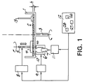
- FIG. 1 is a schematic of a polishing device which may be operated according to the method of the present invention.
- a cylindrical vessel 1 contains magnetorheological polishing fluid (MP-fluid) 2.
- the MP-fluid 2 contains an abrasive.
- Vessel 1 is preferably constructed of a non-magnetic material which is inert to the MP-fluid 2.
- vessel 1 is semi-cylindrically shaped in cross-section and has a flat bottom. However, the particular shape of vessel 1 may be modified to suit the workpiece to be polished, as will be described in greater detail.
- a workpiece 4 to be polished is connected to a rotatable workpiece spindle 5.
- Workpiece spindle 5 is preferably made from a non-magnetic material.
- Workpiece spindle 5 is mounted on a spindle slide 8, and can be moved in the vertical direction.
- Spindle slide 8 may be driven by a conventional servomotor which operates according to electrical signals from a programmable control system 12.
- vessel spindle 3 Rotation of vessel 1 is controlled by vessel spindle 3, which is preferably positioned in a central location below vessel 1.
- Vessel spindle 3 can be driven by conventional motor or other power source.
- An electromagnet 6 is positioned adjacent to vessel 1 so as to be capable of influencing the MP-fluid 2 in a region containing the workpiece 4. Electromagnet 6 should be capable of inducing a magnetic field sufficient to carry out the polishing operation, and preferably will induce a magnetic field of at least about 100 kA/m. Electromagnet 6 is activated by winding 7 from power supply unit 11 which is connected to control system 12. Winding 7 can be any conventional magnetic winding. Electromagnet 6 is set up on an electromagnet slide 9 and can be moved in a horizontal direction, preferably along the radius of vessel 1. Electromagnet slide 9 may be driven by a conventional servomotor which operates according to electrical signals from the programmable control system 12.
- Winding 7 is activated by power supply unit 11 during polishing to induce a magnetic field and influence the MP-fluid 2.
- MP-fluid 2 is acted on by a nonuniform magnetic field in a region adjacent to the workpiece 4.
- equal-intensity lines of the field are normal, or perpendicular, to the gradient of said field, and the force of the magnetic field is a gradient directed toward the vessel bottom normal to the surface of workpiece 4.
- Application of the magnetic field from electromagnet 6 causes the MP-fluid 2 to change its viscosity and plasticity in a limited polishing zone 10 adjacent to the surface being polished.
- the size of the polishing zone 10 is defined by the gap between the pole-pieces of the electromagnet 6 and the shape of the tips of the electromagnet 6.
- Abrasive particles in the MP-fluid are preferably acted upon by the MP-fluid substantially only in polishing zone 10, and the pressure of MP-fluid against the surface of workpiece 4 is largest in the polishing zone 10.
- an MP-fluid comprising a plurality of magnetic particles, a stabilizer, and a carrying fluid selected from the group consisting of water and glycerin, is used.
- the magnetic particles preferably carbonyl iron particles
- the protective layer is preferably resistent to mechanical stresses, and as thin as practicable.
- the coating material is teflon. The particles may be coated by the usual process of microcapsulation.
- the polishing machine shown in Figure 1 can operate as follows. Workpiece 4 is coupled to workpiece spindle 5, and positioned by spindle slide 8 at a clearance, h, with respect to the bottom of vessel 1 so that preferably a portion of the workpiece 4 to be polished is immersed in the MP-fluid 2.
- Said clearance h may be any suitable clearance which will permit polishing of the workpiece.
- the clearance h will affect the material removal rate V for the workpiece 4, as illustrated in Figure 8, and will also affect the size of a contact spot R z at which the polishing zone 10 contacts the workpiece 4.
- the clearance h is preferably chosen so that the surface area of the contact spot R z is less than one third of the surface area of the workpiece 4.
- the clearance h may be changed during the polishing process.
- both workpiece 4 and vessel 1 are rotated, preferably counter to each other.
- Vessel spindle 3 is put into rotating motion, thereby rotating vessel 1.
- Vessel spindle 3 rotates about a central axis and preferably rotates vessel 1 at a speed sufficient to effect polishing but insufficient to generate a centrifugal force sufficient to substantially eject or spray MP-fluid 2 out of vessel 1.
- the vessel is rotated at a constant velocity.
- the motion of vessel 1 provides continuous delivery of a fresh portion of MP-fluid 2 to the region where workpiece 4 is located, and provides continuous motion of the MP-fluid 2 in contact with the surface of the workpiece being polished in the polishing zone 10.
- additional carrying fluid preferably water or glycerin, is added during polishing to replenish carrying fluid that has vaporized, and thus maintain the properties of the fluid.
- Workpiece spindle 5 is also rotated, about a central axis, to provide rotating movement to workpiece 4.
- workpiece spindle 5 operates at speeds of up to 2000 rpm, with about 500 rpm particularly preferred.
- the motion of workpiece spindle 5 continuously brings a fresh part of the surface of the workpiece 4 into contact with the polishing zone 10, so that material removal along the circumference of the surface being polished will be substantially uniform.
- polishing is accomplished in one or more cycles, with an incremental amount of material removed from the workpiece in each cycle. Polishing of the whole surface of the workpiece 4 is achieved by radial displacement of the electromagnet 6 using electromagnet slide 9, which causes the polishing zone 10 to move relative to the workpiece surface.
- the radial motion of the electromagnet 6 may be continuous, or in discrete steps. If the movement of the electromagnet 6 is continuous, the optimal velocity U z of electromagnet 6 for each point of the trajectory of motion is calculated.
- R z is a function of the clearance h, as described above.
- the material removal rate, V can be empirically determined given the clearance h and the velocity at which the vessel 1 is rotated.
- the material removal rate V may be determined by measuring the amount of material removed from a given spot in a given time.
- the thickness of the workpiece material layer to be removed during one polishing cycle, k 3 is a function of the accuracy required for the finished workpiece; k 3 may be selected to minimize local error accumulation. For example, when optical glass is polished, the value of k 3 is determined by the required fit to shape in waves.
- the amount of time for which the contact spot R z should be polished during one cycle, t is calculated according to the formula: t ⁇ k 3 /V
- the number of cycles required and the time required for polishing may be determined.
- N the thickness of the layer of material to be removed during polishing
- K the thickness of the layer of material to be removed during polishing
- Figure 5 shows the relationship of the radius of the workpiece R w , the contact spot R z , the clearance h, and the velocity of the magnet U z for a flat workpiece such as is shown in Figure 1.
- the dwell time at each step must be determined.
- the overall material removal is maintained constant at each step.
- the displacement in a single step, r may be determined empirically using results from preliminary trials, such as those detailed in the example given below.
- control unit 12 may be prepared on the basis of these calculations, for either continuous or stepwise polishing. The whole process of polishing a workpiece 4 may then be conducted under automatic control.
- the control unit 12 preferably includes an input device 26, a processing unit 27, and a signal generator 28.
- the accuracy of figure generation, or correspondence of the finished workpiece to the desired shape and tolerances may be improved by conducting tests to determine the spatial distribution of the removal rate of the material as a function of R z , V[R z ], in the contact spot R z .
- the spatial distribution of the removal rate may be determined by the method of successive approximation, as detailed in the example given below and in Figure 4.
- FIG. 2 there is shown an alternate embodiment of the invention.
- This embodiment achieves highly efficient polishing of convex workpieces 204, such as spherical and nonspherical optical lenses.
- the vessel 201 is a circular trough, and the radius of curvature of the internal wall, adjacent to polishing zone 210, is larger than the largest radius of curvature of workpiece 204.
- polishing it is desirable to minimize the movement of the fluid 202 relative to the vessel 201.
- the internal wall of the vessel 201 may be covered with a layer of a nap, or porous, material 215 to provide reliable mechanical adhesion between the MP-fluid 202 and the wall of the vessel 201.
- Workpiece spindle 205 is connected with spindle slide 208, which is connected with a rotatable table 216.
- the rotatable table 216 is connected to a table slide 217.
- Spindle slide 208, rotatable table 216, and table slide 217 may be driven by conventional servomotors which operate according to electrical signals from programmable control system 212.
- Rotatable table 216 permits workpiece spindle 205 to be continuously rocked about its horizontal axis 214, or permits its positioning at an angle ⁇ with the initial vertical axis 218 of spindle 205.
- Axis 214 preferably is located at the center of curvature of the polished surface at the initial vertical position of the workpiece spindle.
- Spindle slide 208 permits vertical displacement ⁇ of the center of polished surface curvature relative to axis 214.
- Table slide 217 moves the rotatable table 216 with spindle slide 208 and workpiece spindle 205 to obtain, and maintain, the desired clearance h between the polished surface of workpiece 204 and the bottom of vessel 201.
- an electromagnet 206 is stationary, and is positioned below the vessel 201 such that its magnetic gap is symmetric about the workpiece spindle axis 218 when this axis is perpendicular to the plane of polishing zone 210.
- the device illustrated in Figure 2 is the same as the device shown in Figure 1 in all other respects.
- the polishing machine operates as follows. To polish workpiece 204, workpiece spindle 205 with attached workpiece 204 is positioned so that the center of the radius of curvature of workpiece 204 is brought into coincidence with the pivot point (axis of rotation 214) of the rotatable table 216. The removal rate for the workpiece to be polished is then determined experimentally, using a test workpiece similar to the workpiece to be polished. Polishing of work piece 204 may then be conducted automatically by moving its surface relative to polishing zone 210 using rotatable table 216, which rocks workpiece spindle 205 and changes the angle ⁇ according to calculated regimes of treatment.
- R sf represents what the radius of the workpiece would be if it were spherical, based upon the radius of curvature of the actual workpiece 204.
- Rocking of workpiece spindle 205 may be continuous or stepwise. If the workpiece spindle 205 is continuously rocked, the angular velocity ⁇ z of this motion is determined by the formula: ⁇ z ⁇ ⁇ V/k 3 where ⁇ is the angle dimension of the contact spot, V is the material removal rate, and k 3 is the thickness of the workpiece material layer to be removed during one cycle of polishing.
- the dwell time for each step must be calculated. In calculating the dwell time for each step, it is necessary to take the coefficient of overlapping I into account.
- the polishing may be conducted under conditions which yield uniform material removal from each point of the surface, if it is desired that the surface figure should not be altered, or specific material removal goals for each point on the surface may be achieved by varying the dwell time.
- a non-spherical workpiece 204 may be polished to the desired shape by varying the dwell time depending upon the radius of curvature of the section of the workpiece being polished.
- workpiece spindle 205 may also be moved vertically during polishing.
- the calculations previously described may be carried out for each section of the workpiece having a different radius of curvature. As it is rocked to angle ⁇ , the radius of curvature of the section of a non-spherical workpiece being polished changes.
- rocking of the workpiece spindle 205 is accompanied with vertical motion by spindle slide 208 when polishing non-spherical objects.
- the magnetic field strength may also be varied for each stage of treatment during polishing, if desired.
- the material removal rate V is a function of the magnetic field intensity G, as shown in Figure 7. It is therefore possible to change the quantities of the operating parameters, such as dwell time or clearance.
- the magnetic field strength may be used as another means for controlling the polishing process.
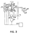
- FIG 3 there is shown an alternate embodiment of the invention.
- the internal wall of the vessel 301 has an additional circular trough which passes through the gap of the electromagnet 306.
- This configuration of the internal wall of the vessel 301 results in a smaller, more focused, polishing zone 310, and an increase in adhesion between the MP-fluid 302 and the vessel 301 is achieved.
- the smaller, more focused, polishing zone will result in a smaller contact spot R z .
- the embodiment depicted in Figure 3 is the same as that depicted in Figure 2.
- the polishing of a glass lens was accomplished, using a device as shown in Figure 2.
- the workpiece 204 had the following initial parameters: a) Glass type BK7 b) Shape Spherical c) Diameter, mm 20 d) Radius of curvature, mm 40 e) Center thickness, mm 15 f) Initial fit to shape, waves 0.5 g) Initial surface roughness, nm, rms 100
- a vessel 201 in which the radius of curvature of the internal wall adjacent to the electromagnet pole pieces 206 was 200 mm, was used. The radius from central axis 219 was 145 mm and the width of the vessel trough was 60 mm.
- the vessel 201 was filled with 300 ml of the MP-fluid 202, having the following composition: Component Weight Percentage Polirit (cerium oxide) 10 Carbonyl iron powder 60 Aerosil (fumed silica) 2.5 Glycerin 5.5 Distilled water balance
- a test workpiece 204 identical to the workpiece to be polished was polished at arbitrarily chosen standard parameters.
- the test workpiece was attached to the workpiece spindle 205 and positioned by spindle slide 208 so that the distance between the workpiece surface to be polished and the pivot point of the rotatable table 216 (axis 214) was equal to 40 mm (the radius of curvature of the workpiece 204 surface).
- the clearance h between the surface of workpiece 204 to be polished and the bottom of the vessel 201 was set at 2 mm using the table slide 217.
- Both the workpiece spindle 205 and the vessel 201 were then rotated.
- the workpiece spindle rotation speed was 500 rpm, and the vessel rotation speed was 150 rpm.
- the electromagnet 206 having a magnet gap equal to 20 mm, was turned on to a level where the magnetic field intensity near the workpiece surface was about 350 kA/m. All parameters were kept constant, and the workpiece was polished for about 10 minutes, which was sufficient to create a well-defined spot.
- the polishing required to finish the workpiece is determined.
- a computer program is used to calculate the necessary parameters and control the polishing operation. Determination of the polishing requirements includes determination of the number of steps for changing angle ⁇ , the value of angle ⁇ for each step, and the dwell time for each step in order to maintain constant the material removal over the surface of the workpiece by overlapping polishing zones, as described above.
- the parameters of the workpiece, parameters of the polishing zone, and spatial distribution of removed material in the polishing zone given above for this example are used to control the system during the polishing method.
- the results were entered into a computer program for this purpose.
- the results of the calculations were as follows:
- control radius represents the relative position of the polishing zone with respect to the central vertical axis of the workpiece.
- the control radius is determined by the angle ⁇ ; during polishing it is the angle ⁇ , rather than the control radius, that is controlled.
- the dwell times for each angle are then converted to minutes by multiplying the time coefficients in table 1 by a constant factor.
- the constant factor used to convert the time coefficients to dwell times will depend upon the characteristics of the workpiece. For the example given here, this constant was empirically determined to be 5 minutes.
- the programmable controller 212 was programmed.
- the workpiece 204 to be polished was attached to the workpiece spindle 205, and the procedure described for the test workpiece was repeated under the automatic control of the programmable controller 212.
- the following results were obtained.
- Figures 9 through 30 there are numerous alternate embodiments of the device of the present invention. Some of these alternate embodiments are shown in Figures 9 through 30. As illustrated by these figures, only a magnetorheological fluid, a means for inducing a magnetic field, and a means for moving the object to be polished or the means for inducing the magnetic field relative to one another are required to construct a device according to the present invention.
- Figures 9 through 11 illustrate an embodiment of the invention in which the magnetorheological fluid is not contained within a vessel.
- an MP-fluid 902 is placed at the poles of an electromagnet 906.
- Electromagnet 906 is positioned so that the magnetic field that it creates acts only upon a particular surface section of the object to be polished 904, thereby creating a polishing zone.
- object 904 is put into rotation.
- Either electromagnet 906, or object 904, or both electromagnet 906 and object 904, are then moved such that step-by-step the entire surface of the object is polished.
- Electromagnet 906, object to be polished 904, or both may be displaced relative to each other in the vertical and/or horizontal planes.
- the magnetic field strength is also regulated, as required, to polish the object 904. Rotation of the object 904, movement of the electromagnet 906 and/or the object 904, and regulation of the magnetic field strength according to a predetermined program of polishing permits controlled removal of material from the surface of the object to be polished 904.
- FIG 10 illustrates a device for polishing curved surfaces.
- an MP-fluid 1002 is placed at the poles of electromagnet 1006.
- the electromagnet 1006 is configured such that it generates a magnetic field affecting only some surface section of an object to be polished 1004.
- Object to be polished 1004 which has a spherical or aspherical surface, is put into rotation.
- Electromagnet 1006 is displaced to an angle ⁇ along the trajectory which corresponds to the radius of curvature of the object 1004, as indicated by the arrows in Figure 10, such that the electromagnet is moved parallel to the surface of the object, according to a predetermined program of polishing, thus controlling material removal along the part surface.
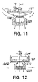
- an MR-fluid 1102 is also placed at the poles of electromagnet 1106.
- the electromagnet is configured such that it generates a magnetic field acting only upon some surface section of the object to be polished 1104.
- an object to be polished 1104 having a spherical or aspherical surface is put into rotation.
- the object to be polished 1104 is then rocked, such that an angle ⁇ , indicated on Fig. 11, varies from 0 to a value which depends upon the size and shape of the workpiece.
- MR-fluid 1202 is placed into a vessel 1201.
- An electromagnet 1206 is positioned beneath vessel 1201 and configured such that the electromagnet 1206 initiates a magnetic field which acts only upon a section, or polishing zone 1210, of the MP-fluid 1202 in the vessel 1201.
- the MP-fluid in the polishing zone 1210 acquires plastic properties for effective material removal in the presence of a magnetic field.
- Object to be polished 1204 is put into rotation, and electromagnet 1206 is displaced along the surface to be polished.
- the workpiece may then be polished according to a predetermined program which controls material removal along the surface of the object to be polished.
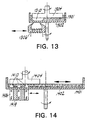
- an MP-fluid 1302 is placed into a vessel 1301.
- Electromagnet 1306 is configured such that it induces a magnetic field acting only upon a section, or polishing zone 1310, of the MP-fluid 1302.
- the MP-fluid 1302 thus acts only upon the section of the object to be polished 1304 positioned in the polishing zone 1310.
- Object to be polished 1304 and vessel 1301, with their axes coinciding, are put into rotation at the same or different speeds in the same or opposite directions.
- Displacing electromagnet 1306 radially along the vessel surface according to an assigned program displaces the polishing zone 1310, and controls material removal along the surface of the object to be polished.
- an MP-fluid 1402 is placed into a vessel 1401.
- a casing 1419 which contains a system of permanent magnets 1406 is set under the vessel 1401.
- An electromagnetic field created by each magnet 1406 affects only a section, or polishing zone 1410, of the object to be polished.
- object to be polished 1404 and vessel 1401 are simultaneously put into rotation.
- the rotation axes of object to be polished 1404 and vessel 1401 are eccentric relative to each other.
- the casing 1419, or the object to be polished 1404, or both, are simultaneously displaced according to a predetermined program of polishing, thus controlling material removal along the object to be polished surface.
- an MP-fluid 1502 is placed into a vessel 1501.
- Electromagnet 1506 is positioned under the vessel such that its magnetic field affects only a section, or polishing zone 1510, of the MP-fluid 1502 in the vessel 1501.
- Object to be polished 1504 which has a spherical or curved shape, and vessel 1501 are put in rotation in the same or opposite directions.
- object 1504 is rocked such that an angle ⁇ , indicated on Fig. 15, varies from 0 to a value which depends upon the size and shape of the object 1504.
- the rotation of the object 1504 and the vessel 1501, and the angle ⁇ are controlled according to a predetermined program of polishing. As a result, material removal along the surface of the object to be polished is controlled.
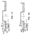
- an MP-fluid 1602 is placed into a longitudinal vessel 1601.
- An electromagnet 1606 is positioned below the vessel 1601 such that it induces a magnetic field in a section, or polishing zone 1610, of the MP-fluid 1602.
- the electromagnet 1606 is displaced along the bottom of the vessel 1601 while the object 1604 and the vessel 1601 are rotating.
- the object is also rocked to an angle ⁇ during the polishing program. Rotation of the object 1604 and vessel 1601, movement of the electromagnet 1606, and rocking the object 1604 according to a predetermined program of polishing permits controlled removal of material from the surface of the object to be polished 904.
- MP-fluid 1702 is placed into a circular vessel with an annular cavity 1701.
- Electromagnet 1706 is positioned under the vessel 1701.
- Electromagnet 1706 is chosen such that its magnetic field affects a section, or polishing zone 1710, of the MP-fluid 1702.
- Object to be polished 1704 and vessel 1701 are put into rotation in the same or opposite directions at equal or different speeds.
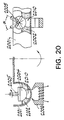
- an MP-fluid 1802 is placed into a circular vessel with an annular cavity 1801.
- the vessel bottom is coated with a nap material 1815, which hinders slippage of the MP-fluid 1802 relative to the vessel bottom 1801, and enhances the rate of material removal from the surface of the object.
- Electromagnet 1806 is mounted under the vessel cavity 1801.
- the pole pieces of the electromagnet 1806 are chosen such that its field will affect only a section, or polishing zone 1810, of the MP-fluid, and therefore it will only affect a portion of the surface of the object to be polished 1804.
- Electromagnet 1806 is also displaced relative to the surface of the object to be polished 1804 according to a program of polishing.
- MP-fluid 1902 is placed into an annular cavity in a circular vessel 1901.
- the radius of curvature of the vessel cavity is chosen to correspond to the desired radius of curvature of the object 1904 after polishing, such that the inner wall of the cavity 1901 will equi-distant to the surface of the polished object 1904.
- Object to be polished 1904 which is mounted on a spindle 1905, and vessel 1901 are put into rotation at equal or different speeds in the same or opposite directions.
- Electromagnet 1906 is displaced along the bottom of the vessel cavity 1901 according to a predetermined program, thus controlling material removal along the surface of the object to be polished.
- the MP-fluid 2002 is also placed into a circular vessel with an annular cavity 2001.
- An electromagnet 2006 is mounted under the vessel 2001.
- the pole pieces of the electromagnet 2006 are chosen such that its field will affect only a section, or polishing zone 2010, of the MP-fluid 2002, and therefore will affect only a surface section of the object to be polished 2004.
- Object to be polished 2004 and the vessel 2001 are put into rotation at the same or fferent speeds in the same or opposite directions.
- the object to be polished 2004 is also rocked, or swung, relative to the vessel.
- the object is rocked from a vertical position to an angle ⁇ during polishing according to a predetermined program, thereby controlling material removal along the surface to be polished.
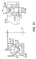
- an MP-fluid 2102 is placed in a circular vessel 2101 with an annular cavity having a valley 2120.
- the pole pieces of electromagnet 2106 are chosen such that its magnetic field will affect only a portion, or polishing zone 2110, of the MP-fluid 2101.
- the portion of the MP-fluid 2102 affected by the magnetic field is located within, or above, the valley 2120.
- An object to be polished 2104 is put into rotation.
- the object to be polished 2104 is also rocked, or swung, relative to its axis normal to the vessel rotation plane to an angle ⁇ , according to an assigned program, thus controlling material removal along the surface of the object to be polished.
- an MP-fluid 2302 is placed into a vessel 2301.
- An electromagnet 2306 is installed below the vessel bottom.
- the pole pieces of the electromagnet are chosen such that it will create a magnetic field which acts only upon a portion, or polishing zone 2310, of the MP-fluid 2302 in the vessel 2301.
- Objects to be polished 2304a, 2304b, etc. are mounted on spindles 2305a, 2305b, etc., which are capable of rotating relative to a disc 2321 on which they are installed.
- Disc 2321 is also capable of rotating relative to vessel 2301.
- Electromagnet 2306 is also radially displaced along the surface of the vessel. This rotation, and displacing electromagnet 2306 along the vessel surface, are regulated to control material removal from the surface of the object to be polished.
- an MP-fluid 2402 is placed into a vessel 2401.
- Electromagnets 2406a, 2406b, etc. are mounted near the vessel bottom.
- the pole pieces of electromagnets 2406a, 2406b, etc. are chosen such that each will create a field acting only upon a section, or polishing zone 2410a, 2410b, etc., of the vessel fluid 2402.
- Objects to be polished 2404a, 2404b, etc. are mounted on spindles 2405a, 2405b, etc. which are capable of rotating relative to a disc 2421 on which they are installed.
- Disc 2421, objects to be polished 2404a, 2404b, etc. and vessel 2401 are put into rotation with equal or different speeds, in the same or opposite directions.
- Electromagnets 2406a, 2406b, etc. are also radially displaced along the bottom surface of the vessel 2401. This rotation, and displacing electromagnets 2406a, 2406b, etc. along the vessel surface, are regulated to control material removal from the surface of the object to be polished.
- an MP-fluid 2802 is placed into vessel 2801.
- Two units 2822a and 2822b equipped with permanently mounted magnets 2823 are installed inside the vessel 2801.
- a flat object to be polished 2804 is mounted between units 2822a and 2822b.
- Units 2822a and 2822b are rotated about their horizontal axes. These units are rotated at the same speed such that a magnetic field, and polishing zones 2810, will be created when different-sign poles are on the contrary with each other.
- Object to be polished 2804 is moved in such a way that polishing zones are created for both object surfaces.
- the material removal rate is controlled by the rotation speed of units 2822a, 2822b and the speed at which the object 2804 is vertically displaced.
- an MP-fluid 2902 is placed into vessel 2901.
- Units 2922 equipped with magnets 2923 are mounted inside vessel 2901 and are capable of rotating along the axis normal to the displacement direction of the object to be polished 2904.
- the magnets are mounted in the unit so that the permanent magnets mounted side by side would have different-sign poles relative to each other, so as to create a polishing zone 2910 between the magnets.
- the polishing is carried out by rotating unit 2922 and giving a scanning motion to object to be polished 2904 in the vertical plane.
- the material removal rate is controlled by changing the rotational speeds of units 2922 and the speed at which object to be polished 2904 is displaced.
Landscapes
- Engineering & Computer Science (AREA)
- Mechanical Engineering (AREA)
- Finish Polishing, Edge Sharpening, And Grinding By Specific Grinding Devices (AREA)
- Constituent Portions Of Griding Lathes, Driving, Sensing And Control (AREA)
Claims (59)
- Verfahren zum Polieren einer Werkstückoberfläche unter Verwendung eines magnetorheologischen Fluids (2) mit den Schritten:Positionieren des Werkstücks (4) mit einem Zwischenraum (h) von einer Oberfläche, die dazu geeignet ist, ein magnetorheologisches Fluid (2) zu tragen;Erzeugen einer Strömung des magnetorheologischen Fluids (2) durch den Zwischenraum (h);Erzeugen eines Magnetfeldes im wesentlichen in dem Zwischenraum (h), um den Polierbereich (10) im magnetorheologischen Fluid (2) zu erzeugen, wobei der Polierbereich (10) ein Übergangswerkzeug bildet, das mit einem Abschnitt der Werkstückoberfläche in Eingriff kommt und veranlaßt, daß in diesem Abschnitt Material von der Werkstückoberfläche abgetragen wird, wobei der Polierbereich (10) mit der Werkstückoberfläche in einem Flächenbereich in Eingriff kommt, der kleiner ist als der zu polierende Flächenbereich der Werkstückoberfläche; undBewegen des Werkstücks (4) bezüglich des Polierbereichs (10) oder des Polierbereichs (10) bezüglich des Werkstücks (4), um verschiedene Abschnitte der Werkstückoberfläche für vorgegebene Verweilzeiten dem Polierbereich (10) auszusetzen, um die Abschnitte der Werkstückoberfläche in vorgegebenen Graden selektiv zu polieren.
- Verfahren nach Anspruch 1, wobei mindestens ein Teil des Zwischenraums (h) in der Höhe von einem ersten zu einem zweiten Abschnitt abnimmt, und wobei das magnetorheologische Fluid (2) in Richtung vom ersten Abschnitt zum zweiten Abschnitt durch den Zwischenraum strömt.
- Verfahren nach Anspruch 1 oder 2, wobei das magnetorheologische Fluid (2) nicht-magnetische Schleifpartikel aufweist, um die Materialabtragung an der Werkstückoberfläche zu verbessern.
- Verfahren nach Anspruch 1, 2 oder 3, ferner mit dem Schritt zum Wiederzuführen des magnetorheologischen Fluids (2), das durch den Zwischenraum (h) geströmt ist, in den Zwischenraum (h).
- Verfahren nach Anspruch 4, ferner mit dem Schritt zum Rühren des magnetorheologischen Fluids (2), das durch den Zwischenraum (h) geströmt ist.
- Verfahren nach Anspruch 5, wobei das magnetorheologische Fluid (2) ein Trägerfluid aufweist, und ferner mit dem Schritt zum Hinzufügen von Trägerfluids zum magnetorheologischen Fluid (2), um verdampftes Trägerfluid zu ersetzen.
- Verfahren nach einem der Ansprüche 1 bis 6, wobei der Schritt zum Erzeugen einer Strömung eines magnetorheologischen Fluids (2) durch den Zwischenraum (h) das Aufbringen von magnetorheologischem Fluid (2) auf die Oberfläche, die dazu geeignet ist, das magnetorheologische Fluid (2) zu tragen, und das Bewegen der Oberfläche bezüglich des Werkstücks (4) aufweist, um das magnetorheologische Fluid (2) durch den Zwischenraum (h) zu zwingen.
- Verfahren nach einem der Ansprüche 1 bis 7, wobei der Schritt zum Erzeugen eines Magnetfeldes den Schritt zum Maximieren des Magnetfeldes im Zwischenraum (h) aufweist.
- Verfahren nach einem der Ansprüche 1 bis 8, ferner mit dem Schritt zum Drehen des Werkstücks (4) bezüglich des Polierbereichs (10).
- Verfahren nach einem der Ansprüche 1 bis 9, wobei das Werkstück (4) auf einem schwenkbaren Werkstückhalter angeordnet ist, und wobei der Schritt zum Bewegen des Werkstücks (4) bezüglich des Polierbereichs (10) bzw. des Polierbereichs (10) bezüglich des Werkstücks (4) das Schwenken des Werkstückhalters aufweist, um die Oberfläche des Werkstücks (4) über den Polierbereich (10) zu bewegen.
- Verfahren nach einem der Ansprüche 1 bis 9, wobei der Schritt zum Bewegen des Werkstücks (4) bezüglich des Polierbereichs (10) bzw. des Polierbereichs (10) bezüglich des Werkstücks (4) das Bewegen des Werkstücks (4) entlang einer Ebene aufweist.
- Verfahren nach Anspruch 11, wobei der Schritt zum Bewegen des Werkstücks (4) entlang einer Ebene das Bewegen des Werkstücks (4) entlang einer Ebene in eine Richtung aufweist, die im wesentlichen senkrecht zur Strömungsrichtung des magnetorheologischen Fluids (2) durch den Zwischenraum (h) ausgerichtet ist.
- Verfahren nach einem der Ansprüche 1 bis 9, wobei der Schritt zum Bewegen des Werkstücks (4) bezüglich des Polierbereichs (10) bzw. des Polierbereichs (10) bezüglich des Werkstücks (4) das Bewegen des Polierbereichs durch Bewegen des Magnetfeldes bezüglich der Oberfläche aufweist, die dazu geeignet ist, das magnetorheologische Fluid (2) zu tragen.
- Vorrichtung zum Polieren einer Werkstückoberfläche unter Verwendung eines magnetorheologischen Fluids (2) mit:einer Oberfläche zum Tragen eines Volumens eines magnetorheologischen Fluids (2);einem Werkstückhalter zum Halten und Positionieren des Werkstücks (4) mit einem Zwischenraum (h) von der Oberfläche, so daß die Oberfläche eine Strömung des magnetorheologischen Fluids (2) über den Zwischenraum (h) erzwingt;einem Magneten zum Erzeugen eines Magnetfeldes in dem Zwischenraum (h), um einen Polierbereich (10) im magnetorheologischen Fluid zu erzeugen, das durch den Zwischenraum (h) strömt, um ein Übergangspolierwerkzeug zu bilden, das mit einem Abschnitt der Werkstückoberfläche in Eingriff kommt und veranlaßt, daß in diesem Abschnitt Material von der Werkstückoberfläche abgetragen wird, wobei der Polierbereich (10) mit der Werkstückoberfläche in einem Flächenbereich in Eingriff kommt, der kleiner ist als der zu polierende Flächenbereich der Werkstückoberfläche; undeiner Einrichtung zum Bewegen des Werkstücks (4) bezüglich des Polierbereichs (10) oder des Polierbereichs (10) bezüglich des Werkstücks (4), um verschiedene Abschnitte der Werkstückoberfläche für vorgegebene Verweilzeiten dem Polierbereich (10) auszusetzen, um die Abschnitte der Werkstückoberfläche in vorgegebenen Graden selektiv zu polieren.
- Vorrichtung nach Anspruch 14, wobei mindestens ein Teil des Zwischenraums (h) in der Höhe von einem ersten zu einem zweiten Abschnitt abnimmt, und wobei das magnetorheologische Fluid in Richtung vom ersten Abschnitt zum zweiten Abschnitt durch den Zwischenraum (h) strömt.
- Vorrichtung nach Anspruch 14 oder 15, ferner mit einer Einrichtung zum Hinzufügen eines Trägerfluids zum magnetorheologischen Fluid (2), um das Verdampfen von Trägerfluid vom magnetorheologischen Fluid (2) zu kompensieren.
- Vorrichtung nach Anspruch 16, ferner mit einem Mischer zum Rühren des magnetorheologischen Fluids (2).
- Vorrichtung nach einem der Ansprüche 14 bis 17, ferner mit einer Einrichtung zum Drehen des Werkstücks (4) bezüglich des Polierbereichs (10).
- Vorrichtung nach einem der Ansprüche 14 bis 18, wobei das Werkstück (4) auf einem schwenkbaren Werkzeughalter angeordnet ist, um die Oberfläche des Werkstücks (4) über den Polierbereich (10) zu bewegen.
- Vorrichtung nach einem der Ansprüche 14 bis 18, ferner mit einer Einrichtung zum Bewegen des Werkstücks (4) entlang einer Ebene in eine Richtung, die im wesentlichen senkrecht zur Strömungsrichtung des magnetorheologischen Fluids (2) durch den Zwischenraum (h) ausgerichtet ist.
- Verfahren nach einem der Ansprüche 1 bis 13, wobei das magnetorheologische Fluid (2) magnetische Partikel, die mit einer Schutzmaterialschicht beschichtet sind, um zu verhindern, daß sie oxidieren, einen Stabilisator und ein Trägerfluid aufweist.
- Verfahren nach Anspruch 21, wobei das Schutzmaterial ein Polymer aufweist.
- Verfahren nach Anspruch 21 oder 22, wobei das Schutzmaterial Teflon aufweist.
- Verfahren nach einem der Ansprüche 21 bis 23, wobei das Trägerfluid Wasser aufweist.
- Verfahren nach einem der Ansprüche 21 bis 24, wobei das Trägerfluid Glyzerin aufweist.
- Verfahren nach einem der Ansprüche 21 bis 25, wobei die magnetischen Partikel Carbonyleisenpartikel aufweisen.
- Verfahren nach einem der Ansprüche 21 bis 26, wobei das magnetorheologische Fluid ferner Schleifpartikel aufweist.
- Verfahren nach Anspruch 27, wobei die Schleifpartikel CeO2 aufweisen.
- Verfahren nach einem der Ansprüche 1 bis 13, ferner mit den Schritten:Steuern der Konsistenz des Fluids (2) im Polierbereich (10);Bestimmen der Materialabtragrate für das Werkstück (4);Bestimmen der Richtung und der Geschwindigkeit der Bewegung des Polierbereichs (10) bezüglich des Werkstücks (4); undBestimmen der erforderlichen Anzahl von Polierzyklen mit:Bestimmen des anfänglichen quadratischen Mittelwertes der Höhe von Oberflächenunregelmäßigkeiten des Werkstücks (4);Bestimmen der Dicke einer defekten Schicht unter der Oberfläche;Bestimmen der anfänglichen Oberflächenform; undBestimmen der während eines Polierzyklus abzutragenden Materialschichtdicke.
- Verfahren nach Anspruch 29, wobei der Schritt zum Bestimmen der Materialabtragrate für das Werkstück (4) das Bestimmen der räumlichen Verteilung der Materialabtragung aufweist.
- Verfahren nach Anspruch 29 oder 30, wobei die Bewegung des Polierbereichs (10) bezüglich des Werkstücks (4) kontinuierlich ist.
- Verfahren nach einem der Ansprüche 29 bis 31, wobei der Schritt zum Bestimmen der Richtung und der Geschwindigkeit der Bewegung des Polierbereichs bezüglich des Werkstücks (4) aufweist:Bestimmen der Größe eines Kontaktabschnitts des Werkstücks (4), der mit dem Polierbereich (10) in Kontakt steht, zu jedem vorgegebenen Zeitpunkt;Bestimmen der während eines Polierzyklus abzutragenden Materialschichtdicke; undBestimmen der Geschwindigkeit des Polierbereichs (10).
- Verfahren nach Anspruch 29 oder 30, wobei die Bewegung des Polierbereichs (10) bezüglich des Werkstücks (4) in diskreten Schritten erfolgt.
- Verfahren nach Anspruch 33, wobei der Schritt zum Bestimmen der Richtung und der Geschwindigkeit der Bewegung des Polierbereichs (10) bezüglich des Werkstücks (4) aufweist:Bestimmen der Größe eines Kontaktabschnitts des Werkstücks (4), der mit dem Polierbereich (10) in Kontakt steht, zu jedem vorgegebenen Zeitpunkt;Bestimmen des Versatzes des Polierbereichs (10) in einem einzelnen Schritt;Bestimmen eines Überlappungskoeffizienten;Bestimmen der während eines Polierzyklus abzutragenden Materialschichtdicke;Bestimmen der Verweilzeit für jeden Polierschritt; undBestimmen der erforderlichen Anzahl von Polierschritten.
- Verfahren nach einem der Ansprüche 29 bis 34, ferner mit dem Schritt zum Versetzen des Werkstücks (4) von seiner vertikalen Achse um einen Winkel α.
- Verfahren nach Anspruch 35, wobei das Werkstück (4) mit einer kontinuierlichen Geschwindigkeit um einen Winkel α von seiner vertikalen Achse versetzt wird.
- Verfahren nach Anspruch 36, wobei der Schritt zum Versetzen des Werkstücks (4) um einen Winkel α von seiner vertikalen Achse mit einer kontinuierlichen Geschwindigkeit ferner aufweist:Bestimmen des Winkelmaßes des Kontaktbereichs;Bestimmen der während eines Polierzyklus abzutragenden Materialschichtdicke; undBestimmen der Winkelgeschwindigkeit des Versatzes des Werkstücks (4) um den Winkel α.
- Verfahren nach Anspruch 35, wobei das Werkstück (4) in diskreten Schritten um einen Winkel α von seiner vertikalen Achse versetzt wird.
- Verfahren nach Anspruch 38, wobei das Versetzen des Werkstücks (4) in diskreten Schritten um einen Winkel α von seiner vertikalen Achse aufweist:Bestimmen des Winkelmaßes des Kontaktbereichs;Bestimmen der während eines Polierzyklus abzutragenden Materialschichtdicke;Bestimmen des Winkelversatzes für einen einzelnen Schritt;Bestimmen des Überlappungskoeffizienten; undBestimmen der Verweilzeit für jeden Schritt.
- Verfahren nach einem der Ansprüche 29 bis 39, wobei das magnetorheologische Fluid (2) aufweist:mehrere magnetische Partikel;einen Stabilisator; undein Trägerfluid.
- Verfahren nach Anspruch 40, ferner mit dem Schritt zum Steuern der Eigenschaften des magnetorheologischen Fluids (2) durch Nachfüllen des Trägerfluids während des Poliervorgangs.
- Verfahren nach einem der Ansprüche 29 bis 41, wobei das magnetorheologische Fluid in einem Behälter mit einer Referenzoberfläche angeordnet ist.
- Verfahren nach Anspruch 42, wobei der Behälter bezüglich des Werkstücks (4) bewegt wird.
- Verfahren nach Anspruch 43, wobei der Behälter mit vorgegebenen Geschwindigkeiten gedreht wird.
- Verfahren nach Anspruch 42, wobei der Polierbereich (10) eine nominelle Größe von höchstens einem Drittel der Oberfläche des Werkstücks (4) hat.
- Verfahren nach einem der Ansprüche 42 bis 45, wobei der Schritt zum Erzeugen eines Polierbereichs (10) in einem magnetorheologischen Fluid (2) aufweist:Induzieren eines Magnetfeldes in der Nähe des magnetorheologischen Fluids; undSteuern der Richtung und der Intensität des Magnetfeldes.
- Verfahren nach einem der Ansprüche 42 bis 45, wobei der Schritt zum Erzeugen eines Polierbereichs (10) in einem magnetorheologischen Fluid (2) aufweist:Veranlassen, daß das magnetorheologische Fluid in einem Bereich in der Nähe des Werkstücks (4) einem ungleichmäßigen Magnetfeld ausgesetzt wird, das Magnetfeldlinien aufweist, die senkrecht zum Gradienten des Feldes verlaufen.
- Verfahren nach Anspruch 47, wobei der Gradient des Magnetfeldes zum Boden der Referenzoberfläche des Behälters hin gerichtet ist.
- Verfahren nach Anspruch 46, wobei das Magnetfeld durch eine außerhalb des Behälters angeordnete Einrichtung zum Induzieren eines Magnetfeldes erzeugt wird.
- Verfahren nach einem der Ansprüche 42 bis 49, ferner mit dem Schritt zum Bestimmen des Zwischenraums (h) zwischen dem Werkstück (4) und der Refrenzoberfläche des Behälters.
- Verfahren nach Anspruch 46, ferner mit dem Schritt zum Steuern des Poliervorgangs des Werkstücks (4) durch Steuern der Magnetfeldintensität und der Position des Polierbereichs (10) bezüglich der Oberfläche des Werkstücks (4).
- Verfahren nach Anspruch 51, wobei der Poliervorgang durch eine programmierbare Steuereinheit gesteuert wird.
- Verfahren nach einem der Ansprüche 29 bis 52, wobei das magnetorheologische Fluid (2) Polierschleifmaterial aufweist.
- Verfahren nach einem der Ansprüche 29 bis 53, wobei der Schritt zum Bestimmen der Anzahl von Zyklen das Bestimmen der Anzahl von Zyklen gemäß dem folgenden Ausdruck aufweist:
- Verfahren nach Anspruch 34, wobei der Schritt zum Bestimmen der Geschwindigkeit des Polierbereichs (10) das Bestimmen der Geschwindigkeit des Polierbereichs (10) gemäß folgendem Ausdruck aufweist:
- Verfahren nach Anspruch 34, wobei der Schritt zum Bestimmen des Überlappungskoeffizienten das Bestimmen des Überlappungskoeffizienten gemäß dem folgenden Ausdruck aufweist:
- Verfahren nach Anspruch 37, wobei der Schritt zum Bestimmen der Winkelgeschwindigkeit des Versatzes des Werkstücks um einen Winkel α das Bestimmen der Winkelgeschwindigkeit gemäß dem folgendem Ausdruck aufweist:
- Verfahren nach Anspruch 39, wobei der Schritt zum Bestimmen der Verweilzeit in jedem Schritt das Bestimmen der Verweilzeit gemäß dem folgenden Ausdruck aufweist:
- Verfahren nach einem der Ansprüche 40 bis 58, wobei das magnetorheologische Fluid (2) Polierschleifmaterial aufweist.
Applications Claiming Priority (5)
| Application Number | Priority Date | Filing Date | Title |
|---|---|---|---|
| US71813 | 1993-06-04 | ||
| US08/071,813 US5449313A (en) | 1992-04-14 | 1993-06-04 | Magnetorheological polishing devices and methods |
| BY8630193 | 1993-12-09 | ||
| BY863 | 1993-12-09 | ||
| PCT/US1994/006209 WO1994029077A1 (en) | 1993-06-04 | 1994-06-03 | Magnetorheological polishing devices and methods |
Publications (3)
| Publication Number | Publication Date |
|---|---|
| EP0703847A1 EP0703847A1 (de) | 1996-04-03 |
| EP0703847A4 EP0703847A4 (de) | 1997-07-09 |
| EP0703847B1 true EP0703847B1 (de) | 2002-04-10 |
Family
ID=25665737
Family Applications (1)
| Application Number | Title | Priority Date | Filing Date |
|---|---|---|---|
| EP94919329A Expired - Lifetime EP0703847B1 (de) | 1993-06-04 | 1994-06-03 | Magnetorheologische poliervorrichtungen und verfahren |
Country Status (7)
| Country | Link |
|---|---|
| EP (1) | EP0703847B1 (de) |
| JP (2) | JPH08510695A (de) |
| KR (1) | KR100335219B1 (de) |
| AT (1) | ATE215869T1 (de) |
| CA (3) | CA2497731C (de) |
| DE (1) | DE69430370T2 (de) |
| WO (1) | WO1994029077A1 (de) |
Cited By (3)
| Publication number | Priority date | Publication date | Assignee | Title |
|---|---|---|---|---|
| CN102284890A (zh) * | 2011-09-26 | 2011-12-21 | 厦门大学 | 面形自适应回转轴对称光学元件抛光装置 |
| US9707658B2 (en) | 2010-07-09 | 2017-07-18 | Corning Incorporated | Edge finishing apparatus |
| WO2019243914A1 (en) * | 2018-06-19 | 2019-12-26 | Hamid Reza Radnezhad | Magnetic abrasive finishing of curved surfaces |
Families Citing this family (24)
| Publication number | Priority date | Publication date | Assignee | Title |
|---|---|---|---|---|
| EP0687525A1 (de) * | 1994-06-13 | 1995-12-20 | Read-Rite Corporation | Lappsystem zur automatisierten Oberflächenformgebung |
| JP4805640B2 (ja) * | 2005-09-16 | 2011-11-02 | 株式会社リコー | 表面処理装置 |
| JP2007326183A (ja) * | 2006-06-08 | 2007-12-20 | Fdk Corp | 磁気研磨液 |
| US7364493B1 (en) | 2006-07-06 | 2008-04-29 | Itt Manufacturing Enterprises, Inc. | Lap grinding and polishing machine |
| KR100788796B1 (ko) | 2006-11-20 | 2007-12-27 | 연세대학교 산학협력단 | 집속이온빔과 mrf를 이용한 나노 구조물의 제조방법 |
| US8974268B2 (en) * | 2010-06-25 | 2015-03-10 | Corning Incorporated | Method of preparing an edge-strengthened article |
| JP5124034B2 (ja) * | 2011-06-14 | 2013-01-23 | 有限会社村松研磨工業 | バレル研磨装置 |
| EA024869B1 (ru) * | 2013-12-27 | 2016-10-31 | Государственное Научное Учреждение "Институт Тепло- И Массообмена Имени А.В. Лыкова Национальной Академии Наук Беларуси" | Способ магнитореологического формообразования и полирования поверхности сложной формы |
| CN104308671B (zh) * | 2014-10-09 | 2017-01-11 | 东北大学 | 一种磁流变抛光装置与方法 |
| CN105014484A (zh) * | 2015-08-17 | 2015-11-04 | 宇环数控机床股份有限公司 | 磁流变抛光设备的磁场发生装置 |
| CN107378651A (zh) * | 2017-08-04 | 2017-11-24 | 北京交通大学 | 一种磁流变平面抛光装置 |
| KR101932413B1 (ko) * | 2017-08-29 | 2018-12-27 | 인하대학교 산학협력단 | 표면광택 생성장치 |
| KR101994029B1 (ko) * | 2018-01-02 | 2019-09-30 | 인하대학교 산학협력단 | 평면 연마 장치 |
| CN108789117B (zh) * | 2018-06-20 | 2020-05-05 | 中国科学院上海光学精密机械研究所 | 米级大口径光学元件高效抛光机及抛光方法 |
| CN109623507A (zh) * | 2019-01-02 | 2019-04-16 | 中国科学院上海光学精密机械研究所 | Yag板条激光晶体反射面形加工方法 |
| CN110421412A (zh) * | 2019-09-05 | 2019-11-08 | 河北工业大学 | 一种小型磁流变平面抛光装置 |
| CN112123029B (zh) * | 2020-09-25 | 2022-09-06 | 山东理工大学 | 一种基于磁场辅助的微细结构振动光整装置及光整方法 |
| CN112536649A (zh) * | 2020-12-21 | 2021-03-23 | 浙江师范大学 | 一种基于磁性磨粒流的光学玻璃抛光方法及其装置 |
| CN113561035B (zh) * | 2021-07-30 | 2023-04-11 | 西安工业大学 | 一种点云交变磁流变抛光装置及方法 |
| CN113752098B (zh) * | 2021-09-29 | 2022-06-21 | 哈尔滨工业大学 | 一种基于水浴加热辅助的小球头磁流变抛光方法 |
| CN113941904B (zh) * | 2021-10-29 | 2022-07-29 | 哈尔滨工业大学 | 一种基于小型回转体零件旋转超声振动的小球头磁流变抛光工艺方法 |
| CN113878413B (zh) * | 2021-11-15 | 2022-12-13 | 华圭精密科技(东莞)有限公司 | 一种抛光防撞磁流变抛光机与控制方法 |
| CN114055258B (zh) * | 2021-11-19 | 2023-04-18 | 浙江师范大学 | 一种磁性抛光装置及磁性抛光控制方法 |
| CN117428580B (zh) * | 2023-12-15 | 2024-03-19 | 成都市凯林机械贸易有限责任公司 | 一种阀门加工用抛光装置 |
Family Cites Families (18)
| Publication number | Priority date | Publication date | Assignee | Title |
|---|---|---|---|---|
| US2735231A (en) * | 1953-05-22 | 1956-02-21 | Reflectone Corp | simjian |
| US3848363A (en) * | 1973-02-20 | 1974-11-19 | Minnesota Mining & Mfg | Apparatus for treating objects with particles moved by magnetic force |
| US3897350A (en) * | 1974-05-30 | 1975-07-29 | Mobil Oil Corp | Anti-rust compositions |
| US4186528A (en) * | 1978-05-23 | 1980-02-05 | Kosobutsky Alexandr A | Machine for treating spherical surfaces of parts with magneto-abrasive powder |
| US4485024A (en) * | 1982-04-07 | 1984-11-27 | Nippon Seiko Kabushiki Kaisha | Process for producing a ferrofluid, and a composition thereof |
| JPS6067057A (ja) * | 1983-09-21 | 1985-04-17 | Taihoo Kogyo Kk | 研磨方法 |
| JPS6173305A (ja) * | 1984-09-18 | 1986-04-15 | Tdk Corp | 磁性流体 |
| JPS6167045A (ja) * | 1984-09-10 | 1986-04-07 | Canon Inc | トナ−塗布方法 |
| DD227372A1 (de) * | 1984-10-25 | 1985-09-18 | Orsta Hydraulik Veb K | Verfahren zur feinstbearbeitung von stahlrohren |
| SE464565B (sv) * | 1987-02-09 | 1991-05-13 | Jgc Corp | Foerfarande foer slipning med anvaendning av ett magnetiskt fluidum och anordning daerfoer |
| JPS63232402A (ja) * | 1987-03-20 | 1988-09-28 | Nippon Seiko Kk | 導電性磁性流体組成物とその製造方法 |
| US4839074A (en) * | 1987-05-22 | 1989-06-13 | Exxon Chemical Patents Inc. | Specified C14 -carboxylate/vinyl ester polymer-containing compositions for lubricating oil flow improvement |
| JPH01303446A (ja) * | 1988-06-01 | 1989-12-07 | Asahi Chem Ind Co Ltd | 磁性粒子とその製造方法 |
| JP2632943B2 (ja) * | 1988-07-26 | 1997-07-23 | 戸田工業株式会社 | 磁気記録媒体 |
| JP2949289B2 (ja) * | 1989-03-28 | 1999-09-13 | 日本エクスラン工業株式会社 | ポリマー被覆磁性粒子の製造法 |
| US4992190A (en) * | 1989-09-22 | 1991-02-12 | Trw Inc. | Fluid responsive to a magnetic field |
| JP3069612B2 (ja) * | 1990-06-13 | 2000-07-24 | 科学技術庁金属材料技術研究所長 | 磁性流体及びその製造方法 |
| JP2889664B2 (ja) * | 1990-07-19 | 1999-05-10 | 株式会社リコー | 回転量測定方法 |
-
1994
- 1994-06-03 WO PCT/US1994/006209 patent/WO1994029077A1/en active IP Right Grant
- 1994-06-03 KR KR1019950705488A patent/KR100335219B1/ko not_active IP Right Cessation
- 1994-06-03 JP JP7501936A patent/JPH08510695A/ja not_active Withdrawn
- 1994-06-03 CA CA002497731A patent/CA2497731C/en not_active Expired - Lifetime
- 1994-06-03 EP EP94919329A patent/EP0703847B1/de not_active Expired - Lifetime
- 1994-06-03 DE DE69430370T patent/DE69430370T2/de not_active Expired - Lifetime
- 1994-06-03 AT AT94919329T patent/ATE215869T1/de not_active IP Right Cessation
- 1994-06-03 CA CA2497732A patent/CA2497732C/en not_active Expired - Lifetime
- 1994-06-03 CA CA002163671A patent/CA2163671C/en not_active Expired - Lifetime
-
2004
- 2004-08-19 JP JP2004239946A patent/JP4741212B2/ja not_active Expired - Lifetime
Cited By (3)
| Publication number | Priority date | Publication date | Assignee | Title |
|---|---|---|---|---|
| US9707658B2 (en) | 2010-07-09 | 2017-07-18 | Corning Incorporated | Edge finishing apparatus |
| CN102284890A (zh) * | 2011-09-26 | 2011-12-21 | 厦门大学 | 面形自适应回转轴对称光学元件抛光装置 |
| WO2019243914A1 (en) * | 2018-06-19 | 2019-12-26 | Hamid Reza Radnezhad | Magnetic abrasive finishing of curved surfaces |
Also Published As
| Publication number | Publication date |
|---|---|
| CA2497731A1 (en) | 1994-12-22 |
| CA2497732A1 (en) | 1994-12-22 |
| ATE215869T1 (de) | 2002-04-15 |
| KR960702786A (ko) | 1996-05-23 |
| JP4741212B2 (ja) | 2011-08-03 |
| CA2163671C (en) | 2005-10-25 |
| JPH08510695A (ja) | 1996-11-12 |
| EP0703847A1 (de) | 1996-04-03 |
| KR100335219B1 (ko) | 2002-11-07 |
| DE69430370T2 (de) | 2002-12-12 |
| CA2497731C (en) | 2006-02-07 |
| JP2005040944A (ja) | 2005-02-17 |
| CA2163671A1 (en) | 1994-12-22 |
| WO1994029077A1 (en) | 1994-12-22 |
| EP0703847A4 (de) | 1997-07-09 |
| DE69430370D1 (de) | 2002-05-16 |
| CA2497732C (en) | 2011-03-01 |
Similar Documents
| Publication | Publication Date | Title |
|---|---|---|
| EP0703847B1 (de) | Magnetorheologische poliervorrichtungen und verfahren | |
| US5577948A (en) | Magnetorheological polishing devices and methods | |
| US7261616B2 (en) | Magnetorheological polishing devices and methods | |
| EP0858381B1 (de) | Deterministische magnetorheologische feinstbearbeitung | |
| US6746310B2 (en) | Uniform thin films produced by magnetorheological finishing | |
| KR101226757B1 (ko) | 광학 표면 및 반도체 표면을 조연마 및 미세 연마하기 위한유체역학적 방사상 유속 툴 | |
| WO1997014532A9 (en) | Deterministic magnetorheological finishing | |
| Kordonski et al. | Magnetorheological-suspension-based finishing technology | |
| CN106271968B (zh) | 一种磁流变弹性抛光轮、小口径非球面加工装置及方法 | |
| Feng et al. | Effect of the components of Magnetic Compound Fluid (MCF) slurry on polishing characteristics in aspheric-surface finishing with the doughnut-shaped MCF tool | |
| JPS63267155A (ja) | 研磨装置 | |
| KR102068538B1 (ko) | 자기유변유체를 이용한 연마장치 및 그것을 이용한 연마방법 | |
| Kordonski et al. | Magnetorheological suspension-based high precision finishing technology (MRF) | |
| JPH08257897A (ja) | 中心に穴を有する浮子と砥粒を含む磁性流体の循環装 置のある球体の研磨方法及びその装置 | |
| JPH0716870B2 (ja) | 研磨装置 | |
| SU865619A1 (ru) | Способ обработки асферических поверхностей оптических деталей | |
| JP2553538Y2 (ja) | 液浸式研磨装置の研磨液攪拌機構 | |
| JPS63221966A (ja) | 非接触研磨方法 | |
| CN117733661A (zh) | 一种光学元件超光滑表面的高抛方法及高抛设备 | |
| JPS61125759A (ja) | 非球面等の研磨方法 | |
| JPH0623663A (ja) | 超平滑化非接触研磨方法および装置 | |
| JPS63232933A (ja) | 研磨方法及び研磨装置 | |
| JPH08229793A (ja) | 光学素子の研磨装置 |
Legal Events
| Date | Code | Title | Description |
|---|---|---|---|
| PUAI | Public reference made under article 153(3) epc to a published international application that has entered the european phase |
Free format text: ORIGINAL CODE: 0009012 |
|
| 17P | Request for examination filed |
Effective date: 19960104 |
|
| AK | Designated contracting states |
Kind code of ref document: A1 Designated state(s): AT BE CH DE DK ES FR GB GR IE IT LI LU MC NL PT SE |
|
| A4 | Supplementary search report drawn up and despatched | ||
| AK | Designated contracting states |
Kind code of ref document: A4 Designated state(s): AT BE CH DE DK ES FR GB GR IE IT LI LU MC NL PT SE |
|
| 17Q | First examination report despatched |
Effective date: 19990422 |
|
| GRAG | Despatch of communication of intention to grant |
Free format text: ORIGINAL CODE: EPIDOS AGRA |
|
| GRAG | Despatch of communication of intention to grant |
Free format text: ORIGINAL CODE: EPIDOS AGRA |
|
| GRAG | Despatch of communication of intention to grant |
Free format text: ORIGINAL CODE: EPIDOS AGRA |
|
| GRAH | Despatch of communication of intention to grant a patent |
Free format text: ORIGINAL CODE: EPIDOS IGRA |
|
| REG | Reference to a national code |
Ref country code: GB Ref legal event code: IF02 |
|
| GRAH | Despatch of communication of intention to grant a patent |
Free format text: ORIGINAL CODE: EPIDOS IGRA |
|
| GRAA | (expected) grant |
Free format text: ORIGINAL CODE: 0009210 |
|
| AK | Designated contracting states |
Kind code of ref document: B1 Designated state(s): AT BE CH DE DK ES FR GB GR IE IT LI LU MC NL PT SE |
|
| PG25 | Lapsed in a contracting state [announced via postgrant information from national office to epo] |
Ref country code: LI Free format text: LAPSE BECAUSE OF FAILURE TO SUBMIT A TRANSLATION OF THE DESCRIPTION OR TO PAY THE FEE WITHIN THE PRESCRIBED TIME-LIMIT Effective date: 20020410 Ref country code: GR Free format text: LAPSE BECAUSE OF FAILURE TO SUBMIT A TRANSLATION OF THE DESCRIPTION OR TO PAY THE FEE WITHIN THE PRESCRIBED TIME-LIMIT Effective date: 20020410 Ref country code: CH Free format text: LAPSE BECAUSE OF FAILURE TO SUBMIT A TRANSLATION OF THE DESCRIPTION OR TO PAY THE FEE WITHIN THE PRESCRIBED TIME-LIMIT Effective date: 20020410 Ref country code: BE Free format text: LAPSE BECAUSE OF FAILURE TO SUBMIT A TRANSLATION OF THE DESCRIPTION OR TO PAY THE FEE WITHIN THE PRESCRIBED TIME-LIMIT Effective date: 20020410 Ref country code: AT Free format text: LAPSE BECAUSE OF FAILURE TO SUBMIT A TRANSLATION OF THE DESCRIPTION OR TO PAY THE FEE WITHIN THE PRESCRIBED TIME-LIMIT Effective date: 20020410 |
|
| REF | Corresponds to: |
Ref document number: 215869 Country of ref document: AT Date of ref document: 20020415 Kind code of ref document: T |
|
| REG | Reference to a national code |
Ref country code: CH Ref legal event code: EP |
|
| REG | Reference to a national code |
Ref country code: IE Ref legal event code: FG4D |
|
| REF | Corresponds to: |
Ref document number: 69430370 Country of ref document: DE Date of ref document: 20020516 |
|
| PG25 | Lapsed in a contracting state [announced via postgrant information from national office to epo] |
Ref country code: MC Free format text: LAPSE BECAUSE OF NON-PAYMENT OF DUE FEES Effective date: 20020603 Ref country code: LU Free format text: LAPSE BECAUSE OF NON-PAYMENT OF DUE FEES Effective date: 20020603 |
|
| PG25 | Lapsed in a contracting state [announced via postgrant information from national office to epo] |
Ref country code: PT Free format text: LAPSE BECAUSE OF FAILURE TO SUBMIT A TRANSLATION OF THE DESCRIPTION OR TO PAY THE FEE WITHIN THE PRESCRIBED TIME-LIMIT Effective date: 20020710 Ref country code: DK Free format text: LAPSE BECAUSE OF FAILURE TO SUBMIT A TRANSLATION OF THE DESCRIPTION OR TO PAY THE FEE WITHIN THE PRESCRIBED TIME-LIMIT Effective date: 20020710 |
|
| ET | Fr: translation filed | ||
| REG | Reference to a national code |
Ref country code: CH Ref legal event code: PL |
|
| PG25 | Lapsed in a contracting state [announced via postgrant information from national office to epo] |
Ref country code: ES Free format text: LAPSE BECAUSE OF FAILURE TO SUBMIT A TRANSLATION OF THE DESCRIPTION OR TO PAY THE FEE WITHIN THE PRESCRIBED TIME-LIMIT Effective date: 20021030 |
|
| PLBE | No opposition filed within time limit |
Free format text: ORIGINAL CODE: 0009261 |
|
| STAA | Information on the status of an ep patent application or granted ep patent |
Free format text: STATUS: NO OPPOSITION FILED WITHIN TIME LIMIT |
|
| 26N | No opposition filed |
Effective date: 20030113 |
|
| REG | Reference to a national code |
Ref country code: GB Ref legal event code: 732E |
|
| NLS | Nl: assignments of ep-patents |
Owner name: QED TECHNOLOGIES INTERNATIONAL, INC. Effective date: 20071129 |
|
| PGFP | Annual fee paid to national office [announced via postgrant information from national office to epo] |
Ref country code: IE Payment date: 20130330 Year of fee payment: 20 |
|
| PGFP | Annual fee paid to national office [announced via postgrant information from national office to epo] |
Ref country code: GB Payment date: 20130529 Year of fee payment: 20 Ref country code: SE Payment date: 20130607 Year of fee payment: 20 |
|
| PGFP | Annual fee paid to national office [announced via postgrant information from national office to epo] |
Ref country code: NL Payment date: 20130620 Year of fee payment: 20 Ref country code: IT Payment date: 20130617 Year of fee payment: 20 Ref country code: FR Payment date: 20130618 Year of fee payment: 20 |
|
| PGFP | Annual fee paid to national office [announced via postgrant information from national office to epo] |
Ref country code: DE Payment date: 20130628 Year of fee payment: 20 |
|
| REG | Reference to a national code |
Ref country code: DE Ref legal event code: R071 Ref document number: 69430370 Country of ref document: DE |
|
| REG | Reference to a national code |
Ref country code: NL Ref legal event code: V4 Effective date: 20140603 |
|
| REG | Reference to a national code |
Ref country code: GB Ref legal event code: PE20 Expiry date: 20140602 |
|
| REG | Reference to a national code |
Ref country code: SE Ref legal event code: EUG |
|
| REG | Reference to a national code |
Ref country code: IE Ref legal event code: MK9A |
|
| PG25 | Lapsed in a contracting state [announced via postgrant information from national office to epo] |
Ref country code: GB Free format text: LAPSE BECAUSE OF EXPIRATION OF PROTECTION Effective date: 20140602 |
|
| PG25 | Lapsed in a contracting state [announced via postgrant information from national office to epo] |
Ref country code: DE Free format text: LAPSE BECAUSE OF EXPIRATION OF PROTECTION Effective date: 20140604 |
|
| PG25 | Lapsed in a contracting state [announced via postgrant information from national office to epo] |
Ref country code: IE Free format text: LAPSE BECAUSE OF EXPIRATION OF PROTECTION Effective date: 20140603 |