EP0703486A1 - Apparat zur Behandlung eines photographischen Filmes - Google Patents
Apparat zur Behandlung eines photographischen Filmes Download PDFInfo
- Publication number
- EP0703486A1 EP0703486A1 EP95114711A EP95114711A EP0703486A1 EP 0703486 A1 EP0703486 A1 EP 0703486A1 EP 95114711 A EP95114711 A EP 95114711A EP 95114711 A EP95114711 A EP 95114711A EP 0703486 A1 EP0703486 A1 EP 0703486A1
- Authority
- EP
- European Patent Office
- Prior art keywords
- film
- planar member
- processing apparatus
- guide
- film processing
- Prior art date
- Legal status (The legal status is an assumption and is not a legal conclusion. Google has not performed a legal analysis and makes no representation as to the accuracy of the status listed.)
- Granted
Links
Images


Classifications
-
- G—PHYSICS
- G03—PHOTOGRAPHY; CINEMATOGRAPHY; ANALOGOUS TECHNIQUES USING WAVES OTHER THAN OPTICAL WAVES; ELECTROGRAPHY; HOLOGRAPHY
- G03D—APPARATUS FOR PROCESSING EXPOSED PHOTOGRAPHIC MATERIALS; ACCESSORIES THEREFOR
- G03D13/00—Processing apparatus or accessories therefor, not covered by groups G11B3/00 - G11B11/00
-
- G—PHYSICS
- G03—PHOTOGRAPHY; CINEMATOGRAPHY; ANALOGOUS TECHNIQUES USING WAVES OTHER THAN OPTICAL WAVES; ELECTROGRAPHY; HOLOGRAPHY
- G03D—APPARATUS FOR PROCESSING EXPOSED PHOTOGRAPHIC MATERIALS; ACCESSORIES THEREFOR
- G03D15/00—Apparatus for treating processed material
- G03D15/10—Mounting, e.g. of processed material in a frame
Definitions
- the present invention relates to a film processing apparatus for cutting a negative film strip into separate pieces and automatically inserting each separate film piece into a negative-film sheet holder. More particularly, the invention relates to a film processing apparatus of the above-noted type including a film inserting device operable to receive negative film strips cut into a predetermined length and transported from a film transporting device and then to insert the film strips one after another into each independent film-holding pocket of the negative-film sheet holder to be stored therein.
- a bar-like member is disposed at the position on the film transporting passage defining a film inserting opening. This bar-like member is pivotable when contacting a jammed negative film. And, a jamming detection sensor is provided to be operable by the pivotal movement of the bar-like member.
- the detectable area of the member is inevitably limited.
- the condition of the jamming such as when a side edge of the film comes into engagement with the bar-like member disposed at the width-wise center of the film or when a curled leading end of the film strip comes into engagement with the bar-like member, it takes some time for the sensor to detect the jamming.
- the sensor may detect the jamming, this detection may be too late. So that, the sensor cannot fully achieve its original object.
- the primary object of the present invention is to provide a film processing apparatus which allows immediate and reliable detection of jamming trouble of films.
- a film processing apparatus for fulfilling the above-noted object, comprises: a film inserting device operable to receive negative film strips cut into a predetermined length and transported from a film transporting device and then to insert the film strips one after another into each independent film-holding pocket of a film sheet holder; a planar member disposed adjacent an inserting opening of the film sheet holder and displaceable by contacting the film being transported; and a jamming detection sensor for detecting a jammed condition of the film according to a displacement of the planar member.
- the invention has achieved its intended object of providing a film processing apparatus which allows immediate and reliable detection of jamming trouble of films and which therefore may continuously effect the automatic operation for a long period of time with high operational efficiency.
- the planar member acts also as a guide for guiding the film in an introducing passage of the film into the sheet holder.
- the planar member which is provided originally for the purpose of detection of jamming, acts also as a guide for the film.
- the construction provided for the jamming detection may be utilized also for the transportation of the film.
- this guide which acts also as the detecting member, is formed so as to extend not only in the vicinity of the film introducing opening but also to extend farther to a more upstream side relative than the opening, then, the detectable range of the film jamming may be advantageously extended in the longitudinal direction of the film also.
- the planar member for jamming detection is utilized also as the film transport guide, the number of necessary components may be reduced. Further, the jamming detection becomes possible for an extended range in the longitudinal direction of the film. As a result, the film processing apparatus having the above-described additional features is further superior as being capable of detecting a film jamming trouble still more reliably.
- a film transport passage extending from a photographic printer device to the film inserting device detachably includes a manual feed guide for allowing a manual feeding of a negative film strip to the film transporting device.
- this construction allows the further possibility of independent use of the film inserting device.
- the manual feed guide may be attached to the film transporting passage extending from the photographic printer device to the film inserting device. So that, by using this manual feed guide, the transported film may be smoothly fed to the film transporting device manually.
- the above construction eliminates the necessity of temporary detachment of a negative mask of the printing device.
- the manual transportation is possible with the simple operation of attaching the manual feed guide to the film transporting passage.
- occurrence of such trouble as film jamming at the time of its insertion may be restricted. So, the manual feeding operation may be effected speedily and smoothly. Accordingly, the film processing apparatus with this feature is more convenient and causes less trouble.
- the film transporting passage includes an opening portion for forming a loop of the film being transported in order to adsorb difference in film processing speeds between the upstream side and the downstream side; and the manual feed guide is detachably attached to the film transporting passage with the opening portion being opened.
- the opening portion formed in the film transporting passage is opened up to form a loop of the film, so that the processing of this film may be effected smoothly even when there exists difference in the processing speeds between the upstream side and the downstream side. Further, in case a manual transportation is needed, this means that the processing is to be effected on a film which has been already cut, so that there is no necessity of forming such loop. Then, by effectively utilizing the above construction to allow attachment and detachment of the manual feed guide at this location when desired, it is possible to avoid providing an additional arrangement dedicated to the purpose of attachment/detachment of the manual feed guide.
- the construction for allowing smooth film transportation regardless of processing speed difference may be effectively utilized also for the attachment and detachment of the manual feed guide. Then, the number of the necessary components may be reduced to render the construction simple and less costly.
- the manual feed guide includes an arcuate guide face for guiding the film from the downstream side in the film transporting direction to a direction converging with the film transporting passage.
- the film may be manually transported from the downstream side into the film transporting passage smoothly and easily.
- the film processing devices such as a developing device and a printer device have significant height to extend rather far above the film transporting device.
- a film may be manually fed and transported with ease from the downstream side with holding the film with a posture in much free space free from other obstacles.
- the manual feeding operation may be effected easily and efficiently.
- a pair of said guide faces are provided across the film inserting passage in opposition to each other in the film transporting direction; and a distance between the two guide faces increases towards the manual feed inserting opening of the manual feed guide.
- the film manually fed may be reliably guided to the film transporting passage by causing the film to pass between the pair of guide faces. Furthermore, since the distance between the pair of guide faces is gradually increased towards the introducing opening. An operator may readily feel and find the introducing opening for the manual feeding of the film. Thereafter, the fed film may be properly oriented as being guided through the gap between the guide faces which gap is gradually reduced.
- the manual feeding operation may be effected still more efficiently.
- the one guide face disposed on the downstream side in the film transporting direction has a curvature smaller than a curvature of the other guide face disposed on the upstream side.
- the upstream guide face is provided with the relatively greater curvature. Hence, a film manually fed from the downstream side in the film transporting direction may be gently received and guided by the upstream guide face having the greater curvature, thereby to preclude the possibility of occurrence of trouble such as bending of the film.
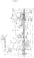
- a film processing apparatus includes, as a serially connected assembly, a printer device A for developing an image of an exposed negative film and printing the image onto a print paper, a film transporting device B for receiving the negative film F transported from a print-assisting automatic negative mask 1 provided at the final processing stage of the printer device A and then transporting this negative film F to the right-hand direction in the figure, and a film inserting device C for automatically and serially inserting the negative film F transported by the film transporting device B into each independent film-holding pocket of a film-storing sheet holder S which is transported in a direction normal to the plane of the figure in synchronism with the transportation of the film F.
- the negative film F after a printing operation (example of film processing operation) thereof using the automatic negative mask 1, is pushed by a drive roller pair 2 provided within the negative mask 1 to be advanced to the right-hand direction in the figure and then this film F is received by a further drive roller pair 3 provided within the film transporting device B to be advanced further to the right to eventually reach the film inserting device C.
- the negative film F is guided by a pair of upper and lower film inserting guides 4A, 4B to be pushed through a vertically opened film inserting opening into each film-holding pocket of the film sheet holder S.
- a light emitting element 6A and a light receiving element 6B of an optical sensor 6 are disposed in opposition to each other across a film transporting passage 5 for counting the number of image frames of the negative film.
- this optical sensor 6 has counted up a predetermined number of image frames; in other words, when a predetermined length of negative film F is detected, the negative film strip F is cut by means of a cutter 7. In the manner described above, while the negative film F is continuously fed, cut film pieces each having the predetermined length may be inserted one after another into the respective film-holding pockets of the film sheet holder S.
- an opening/closing guide 8 which normally constitutes a part of the film transporting passage 5 and which is pivotable about an axis P by an action of an unillustrated solenoid to open up this film transporting passage 5.
- This opening/closing guide 8 is kept closed when e.g. a reprinting operation is to be effected using a negative film F which is already cut, and the guide 8 guides this negative film F using its guide face.
- the guide 8 is pivotably opened to form an opening portion O as indicated by a two-dot chain line in the figure, so as to allow formation of a loop of the negative film F.
- This loop of the negative film F is formed for the purpose of absorbing difference which may be present in the processing speeds between e.g. the transporting speed of the film F and the speed of a printing operation described infra. More specifically, the leading end of the film F is pinched between the drive roller pair 3 to suspend the advancement of the film and then the loop is formed.
- a reference numeral 10 in the figure denotes an optical sensor pair for detecting the limit of the loop formation
- a numeral 11 denotes an assist roller for pushing up the film F from the under to form its loop in the upper area.
- a pair of plate members 12A, 12B adjacent an insertion opening of the film sheet holder S, there are provided a pair of plate members 12A, 12B, with the upper plate member 12A being pivotable. Further, there is provided a jamming detection sensor 13 comprised of a limit switch and activatable in association with a pivotal movement of the plate member 12A caused by its contact with the negative film F.
- a jamming detection sensor 13 comprised of a limit switch and activatable in association with a pivotal movement of the plate member 12A caused by its contact with the negative film F.
- film insertion guides 4A, 4B comprised of a pair of upper and lower guides fixed to each other at the center portions thereof. In operation, when the film insertion guides 4A, 4B are pivoted by contact with the film F to come into contact with and push up the upper plate member 12A, the jamming detection sensor 13 is activated in this case also like the case described supra.
- the film sheet holder S is transported by a pair of rollers 15A, 15B in the direction normal to the transporting direction of the film F.
- the pair of upper and lower film insertion guides 4A, 4B are provided, extending across the transport passage of the negative film F.
- the film insertion guides 4A, 4B function to vertically extend the inserting opening of the pocket of the film sheet holder S to allow smooth insertion of the film F therein.
- the film sheet holder S has its inserting opening extended vertically by the pair of upper and loner film insertion guides 4A, 4B. And, in correspondence with the film insertion guides 4A, 4B and sandwiching the extended opposed ends of the sheet holder S from the above and under, the pair of plate members 12A, 12B are disposed.
- the film insertion guides 4A, 4B are attached to be pivotable about an axis Q, behind which a detecting portion 13A of the jamming detection sensor 13 is disposed.
- a spring 16 biases the film insertion guides 4A, 4B clockwise about the axis Q.
- the detecting portion 13A is pivotable about an axis 13B.
- this detecting portion 13A is biased, by an unillustrated spring, clockwise about the axis 13B so as to constantly maintain its contact with the upper plate member 12A. Further, this upper plate member 12A is attached to be pivotable about an axis R.
- the film insertion guides 4A, 4B comprise a first planar member
- the plate member 12A comprises a second planar member.
- a film processing operation using this film processing apparatus is carried out normally in the above-described manner.
- the negative film F comprises e.g. a half-size film
- the orientation of image recorded on this film differs by 90 degrees from that of the normal, i.e. the full-size type film described above.
- the automatic negative mask 1 will be attached in the direction perpendicular to the normal attaching direction; and in this condition, the film F is transported and a printing operation of the same is effected.
- the above-described construction cannot be used as it is for the transportation of the negative film F; that is, in this case, the film F discharged from the automatic negative mask 1 cannot be directly received, in this condition, by the film transporting device B to be transported thereby. Therefore, in order to allow the possibility of efficient inserting operation of the film F into the film sheet holder S by using the film inserting device C in this special case also, the negative film F needs to be manually fed to the film transporting device B. Further, the same necessity arises also in case such a special operation as a manual printing operation, a trimming operation or the like has been effected.
- a manual feed guide 14 is detachably attached to the film transporting passage 5 for allowing manual feeding of the film F to the drive roller pair 3 of the film transporting device B.
- This manual feed guide 14 may be detachably attached, by means of a magnet M and a positioning pin 15, to the film transporting passage 5 with the opening/closing guide 8 described supra being pivoted to form the opening portion O. Further, with this manual feed guide 14 in operation, the negative film F inserted from the right-hand side, i.e. the downstream side in the film transporting direction as illustrated in Fig.
- the manual insertion opening is formed relatively large to allow easier and smoother manual insertion, and also the inserted film F may be gently received and guided by the upstream guide face 14A having the larger curvature, so that the manual feeding operation of the film F and transporting operation thereafter may be effected without the possibility of such trouble as bending of the leading end of the film.
Landscapes
- Physics & Mathematics (AREA)
- General Physics & Mathematics (AREA)
- Projection-Type Copiers In General (AREA)
- Photographic Processing Devices Using Wet Methods (AREA)
- Feeding Of Articles By Means Other Than Belts Or Rollers (AREA)
- Pile Receivers (AREA)
- Photographic Developing Apparatuses (AREA)
Applications Claiming Priority (6)
| Application Number | Priority Date | Filing Date | Title |
|---|---|---|---|
| JP226662/94 | 1994-09-21 | ||
| JP22666394A JP2780751B2 (ja) | 1994-09-21 | 1994-09-21 | フィルム処理装置 |
| JP22666394 | 1994-09-21 | ||
| JP22666294 | 1994-09-21 | ||
| JP226663/94 | 1994-09-21 | ||
| JP22666294A JP2780750B2 (ja) | 1994-09-21 | 1994-09-21 | フィルム処理装置 |
Publications (2)
| Publication Number | Publication Date |
|---|---|
| EP0703486A1 true EP0703486A1 (de) | 1996-03-27 |
| EP0703486B1 EP0703486B1 (de) | 2002-02-13 |
Family
ID=26527289
Family Applications (1)
| Application Number | Title | Priority Date | Filing Date |
|---|---|---|---|
| EP95114711A Expired - Lifetime EP0703486B1 (de) | 1994-09-21 | 1995-09-19 | Apparat zur Behandlung eines photographischen Filmes |
Country Status (6)
| Country | Link |
|---|---|
| US (1) | US5638157A (de) |
| EP (1) | EP0703486B1 (de) |
| KR (1) | KR100188847B1 (de) |
| CN (1) | CN1066543C (de) |
| CA (1) | CA2158792C (de) |
| DE (1) | DE69525404T2 (de) |
Cited By (1)
| Publication number | Priority date | Publication date | Assignee | Title |
|---|---|---|---|---|
| WO2001023960A1 (en) * | 1999-09-28 | 2001-04-05 | Siral S.R.L. | Automatic machine for inserting sheet-like articles into sleeves as well as sleeve for said machine and method for manufacture thereof |
Families Citing this family (1)
| Publication number | Priority date | Publication date | Assignee | Title |
|---|---|---|---|---|
| US6538718B2 (en) * | 2000-06-05 | 2003-03-25 | Fuji Photo Film Co., Ltd. | Photographic film conveying device |
Citations (5)
| Publication number | Priority date | Publication date | Assignee | Title |
|---|---|---|---|---|
| US3722773A (en) * | 1969-12-29 | 1973-03-27 | G Plate | Jam detector |
| US3823888A (en) * | 1971-05-19 | 1974-07-16 | Agfa Gevaert Ag | Apparatus for detecting and guiding the leaders of photographic roll films |
| JPH03242632A (ja) * | 1990-02-20 | 1991-10-29 | Canon Inc | 画像記録装置 |
| JPH0493930A (ja) * | 1990-08-07 | 1992-03-26 | Canon Inc | プロセッサカメラ |
| EP0516105A2 (de) * | 1991-05-28 | 1992-12-02 | Fuji Photo Film Co., Ltd. | Filmbehälter und automatisches Entwicklungsgerät |
Family Cites Families (3)
| Publication number | Priority date | Publication date | Assignee | Title |
|---|---|---|---|---|
| JPS5821260B2 (ja) * | 1974-08-23 | 1983-04-28 | 京セラミタ株式会社 | フクシヤシサイダンキコウニオケル カミヅマリオボウシシタフクシヤキ |
| US4286869A (en) * | 1979-01-05 | 1981-09-01 | Fuji Photo Film Co., Ltd. | Negative film handling method and apparatus |
| US5374975A (en) * | 1994-02-14 | 1994-12-20 | Amat; Henry W. | Film archival storage holder and method |
-
1995
- 1995-09-19 DE DE69525404T patent/DE69525404T2/de not_active Expired - Fee Related
- 1995-09-19 EP EP95114711A patent/EP0703486B1/de not_active Expired - Lifetime
- 1995-09-20 US US08/531,091 patent/US5638157A/en not_active Expired - Lifetime
- 1995-09-21 KR KR1019950031167A patent/KR100188847B1/ko not_active IP Right Cessation
- 1995-09-21 CA CA002158792A patent/CA2158792C/en not_active Expired - Fee Related
- 1995-09-21 CN CN95117790A patent/CN1066543C/zh not_active Expired - Fee Related
Patent Citations (5)
| Publication number | Priority date | Publication date | Assignee | Title |
|---|---|---|---|---|
| US3722773A (en) * | 1969-12-29 | 1973-03-27 | G Plate | Jam detector |
| US3823888A (en) * | 1971-05-19 | 1974-07-16 | Agfa Gevaert Ag | Apparatus for detecting and guiding the leaders of photographic roll films |
| JPH03242632A (ja) * | 1990-02-20 | 1991-10-29 | Canon Inc | 画像記録装置 |
| JPH0493930A (ja) * | 1990-08-07 | 1992-03-26 | Canon Inc | プロセッサカメラ |
| EP0516105A2 (de) * | 1991-05-28 | 1992-12-02 | Fuji Photo Film Co., Ltd. | Filmbehälter und automatisches Entwicklungsgerät |
Non-Patent Citations (2)
| Title |
|---|
| PATENT ABSTRACTS OF JAPAN vol. 016, no. 032 (P - 1303) 27 January 1992 (1992-01-27) * |
| PATENT ABSTRACTS OF JAPAN vol. 016, no. 319 (P - 1385) 13 July 1992 (1992-07-13) * |
Cited By (1)
| Publication number | Priority date | Publication date | Assignee | Title |
|---|---|---|---|---|
| WO2001023960A1 (en) * | 1999-09-28 | 2001-04-05 | Siral S.R.L. | Automatic machine for inserting sheet-like articles into sleeves as well as sleeve for said machine and method for manufacture thereof |
Also Published As
| Publication number | Publication date |
|---|---|
| CN1066543C (zh) | 2001-05-30 |
| US5638157A (en) | 1997-06-10 |
| CN1143199A (zh) | 1997-02-19 |
| CA2158792A1 (en) | 1996-03-22 |
| EP0703486B1 (de) | 2002-02-13 |
| DE69525404T2 (de) | 2002-11-21 |
| CA2158792C (en) | 2000-05-02 |
| KR960011549A (ko) | 1996-04-20 |
| DE69525404D1 (de) | 2002-03-21 |
| KR100188847B1 (ko) | 1999-06-01 |
Similar Documents
| Publication | Publication Date | Title |
|---|---|---|
| JPH0664370B2 (ja) | 書類シート送り・位置決め装置 | |
| JP3131702B2 (ja) | 自動原稿搬送装置 | |
| US5088405A (en) | Printer with sheet feeding apparatus | |
| US5638157A (en) | Film processing apparatus | |
| US4886352A (en) | Device for conveying photographic paper for use in photograph printing apparatus | |
| JPH0336151A (ja) | 原稿案内装置 | |
| JP2885298B2 (ja) | フィルム処理装置 | |
| JP2788917B2 (ja) | フィルムマガジン装置 | |
| JP2780750B2 (ja) | フィルム処理装置 | |
| JP2780751B2 (ja) | フィルム処理装置 | |
| JP2942676B2 (ja) | 写真焼付装置用搬送制御装置 | |
| EP0784231B1 (de) | Gerät und Verfahren zur Handhabung von Filmbögenträgern | |
| US5794872A (en) | Film feeding apparatus | |
| JPH0596850U (ja) | 片側ローラ搬送ネガキャリア | |
| JP3232459B2 (ja) | 自動原稿搬送装置 | |
| JP2606865B2 (ja) | 写真プリント装置 | |
| JP3452186B2 (ja) | フィルムシートの処理装置 | |
| JP3208924B2 (ja) | 写真処理装置 | |
| JPH0473934B2 (de) | ||
| JPH06347989A (ja) | ペーパカッタ | |
| JPH06166297A (ja) | 封筒等の開封給紙装置 | |
| JPH08188265A (ja) | 画像形成装置 | |
| JPH0331162A (ja) | 原稿案内装置 | |
| JPH07333818A (ja) | 写真ネガフィルム自動挿入装置 | |
| US20050127236A1 (en) | Transporting device and image recording apparatus |
Legal Events
| Date | Code | Title | Description |
|---|---|---|---|
| PUAI | Public reference made under article 153(3) epc to a published international application that has entered the european phase |
Free format text: ORIGINAL CODE: 0009012 |
|
| AK | Designated contracting states |
Kind code of ref document: A1 Designated state(s): CH DE FR GB IT LI |
|
| 17P | Request for examination filed |
Effective date: 19960823 |
|
| 17Q | First examination report despatched |
Effective date: 19991124 |
|
| GRAG | Despatch of communication of intention to grant |
Free format text: ORIGINAL CODE: EPIDOS AGRA |
|
| GRAG | Despatch of communication of intention to grant |
Free format text: ORIGINAL CODE: EPIDOS AGRA |
|
| GRAH | Despatch of communication of intention to grant a patent |
Free format text: ORIGINAL CODE: EPIDOS IGRA |
|
| GRAH | Despatch of communication of intention to grant a patent |
Free format text: ORIGINAL CODE: EPIDOS IGRA |
|
| GRAA | (expected) grant |
Free format text: ORIGINAL CODE: 0009210 |
|
| REG | Reference to a national code |
Ref country code: GB Ref legal event code: IF02 |
|
| AK | Designated contracting states |
Kind code of ref document: B1 Designated state(s): CH DE FR GB IT LI |
|
| PG25 | Lapsed in a contracting state [announced via postgrant information from national office to epo] |
Ref country code: LI Free format text: LAPSE BECAUSE OF FAILURE TO SUBMIT A TRANSLATION OF THE DESCRIPTION OR TO PAY THE FEE WITHIN THE PRESCRIBED TIME-LIMIT Effective date: 20020213 Ref country code: IT Free format text: LAPSE BECAUSE OF FAILURE TO SUBMIT A TRANSLATION OF THE DESCRIPTION OR TO PAY THE FEE WITHIN THE PRE;WARNING: LAPSES OF ITALIAN PATENTS WITH EFFECTIVE DATE BEFORE 2007 MAY HAVE OCCURRED AT ANY TIME BEFORE 2007. THE CORRECT EFFECTIVE DATE MAY BE DIFFERENT FROM THE ONE RECORDED.SCRIBED TIME-LIMIT Effective date: 20020213 Ref country code: CH Free format text: LAPSE BECAUSE OF FAILURE TO SUBMIT A TRANSLATION OF THE DESCRIPTION OR TO PAY THE FEE WITHIN THE PRESCRIBED TIME-LIMIT Effective date: 20020213 |
|
| REG | Reference to a national code |
Ref country code: CH Ref legal event code: EP |
|
| REF | Corresponds to: |
Ref document number: 69525404 Country of ref document: DE Date of ref document: 20020321 |
|
| ET | Fr: translation filed | ||
| REG | Reference to a national code |
Ref country code: CH Ref legal event code: PL |
|
| PLBE | No opposition filed within time limit |
Free format text: ORIGINAL CODE: 0009261 |
|
| STAA | Information on the status of an ep patent application or granted ep patent |
Free format text: STATUS: NO OPPOSITION FILED WITHIN TIME LIMIT |
|
| 26N | No opposition filed |
Effective date: 20021114 |
|
| PGFP | Annual fee paid to national office [announced via postgrant information from national office to epo] |
Ref country code: FR Payment date: 20040908 Year of fee payment: 10 |
|
| PGFP | Annual fee paid to national office [announced via postgrant information from national office to epo] |
Ref country code: GB Payment date: 20040915 Year of fee payment: 10 |
|
| PGFP | Annual fee paid to national office [announced via postgrant information from national office to epo] |
Ref country code: DE Payment date: 20050915 Year of fee payment: 11 |
|
| PG25 | Lapsed in a contracting state [announced via postgrant information from national office to epo] |
Ref country code: GB Free format text: LAPSE BECAUSE OF NON-PAYMENT OF DUE FEES Effective date: 20050919 |
|
| GBPC | Gb: european patent ceased through non-payment of renewal fee |
Effective date: 20050919 |
|
| PG25 | Lapsed in a contracting state [announced via postgrant information from national office to epo] |
Ref country code: FR Free format text: LAPSE BECAUSE OF NON-PAYMENT OF DUE FEES Effective date: 20060531 |
|
| REG | Reference to a national code |
Ref country code: FR Ref legal event code: ST Effective date: 20060531 |
|
| PG25 | Lapsed in a contracting state [announced via postgrant information from national office to epo] |
Ref country code: DE Free format text: LAPSE BECAUSE OF NON-PAYMENT OF DUE FEES Effective date: 20070403 |