EP0702947B1 - Drehteller mit Stand- oder Sitzfläche für Behinderte - Google Patents
Drehteller mit Stand- oder Sitzfläche für Behinderte Download PDFInfo
- Publication number
- EP0702947B1 EP0702947B1 EP95109775A EP95109775A EP0702947B1 EP 0702947 B1 EP0702947 B1 EP 0702947B1 EP 95109775 A EP95109775 A EP 95109775A EP 95109775 A EP95109775 A EP 95109775A EP 0702947 B1 EP0702947 B1 EP 0702947B1
- Authority
- EP
- European Patent Office
- Prior art keywords
- annular element
- base plate
- annular
- rotating plate
- turntable
- Prior art date
- Legal status (The legal status is an assumption and is not a legal conclusion. Google has not performed a legal analysis and makes no representation as to the accuracy of the status listed.)
- Expired - Lifetime
Links
Images

Classifications
-
- A—HUMAN NECESSITIES
- A61—MEDICAL OR VETERINARY SCIENCE; HYGIENE
- A61G—TRANSPORT, PERSONAL CONVEYANCES OR ACCOMMODATION SPECIALLY ADAPTED FOR PATIENTS OR DISABLED PERSONS; OPERATING TABLES OR CHAIRS; CHAIRS FOR DENTISTRY; FUNERAL DEVICES
- A61G7/00—Beds specially adapted for nursing; Devices for lifting patients or disabled persons
- A61G7/10—Devices for lifting patients or disabled persons, e.g. special adaptations of hoists thereto
- A61G7/1073—Parts, details or accessories
- A61G7/1076—Means for rotating around a vertical axis
-
- A—HUMAN NECESSITIES
- A61—MEDICAL OR VETERINARY SCIENCE; HYGIENE
- A61G—TRANSPORT, PERSONAL CONVEYANCES OR ACCOMMODATION SPECIALLY ADAPTED FOR PATIENTS OR DISABLED PERSONS; OPERATING TABLES OR CHAIRS; CHAIRS FOR DENTISTRY; FUNERAL DEVICES
- A61G2200/00—Information related to the kind of patient or his position
- A61G2200/30—Specific positions of the patient
- A61G2200/34—Specific positions of the patient sitting
-
- A—HUMAN NECESSITIES
- A61—MEDICAL OR VETERINARY SCIENCE; HYGIENE
- A61G—TRANSPORT, PERSONAL CONVEYANCES OR ACCOMMODATION SPECIALLY ADAPTED FOR PATIENTS OR DISABLED PERSONS; OPERATING TABLES OR CHAIRS; CHAIRS FOR DENTISTRY; FUNERAL DEVICES
- A61G2200/00—Information related to the kind of patient or his position
- A61G2200/30—Specific positions of the patient
- A61G2200/36—Specific positions of the patient standing
Definitions
- the invention relates to a method for gradually changing the Rotational behavior of one consisting of a base plate and a rotary plate Turntable with which the rotating plate is supported on the base plate.
- Such a turntable is known from US-A-5,000,513.
- the turntable is in central area rotatably held on the base plate by means of a bearing boss and is supported outside of this storage area with an annular surface on the Bottom plate. There is a sliding connection between the rotating plate and the base plate.
- Such turntables are as light as by heavyweight people used. Since the torque depends on the load, a light person needs little torque, but a heavy person a much greater torque.
- the friction pairing has in the known turntable a predetermined coefficient of friction that is tailored to medium-weight people is. The turntable is therefore too easy for light people, the reverse applies for heavy people.
- the object of the invention is to design a turntable of the type mentioned in the introduction, that the turning behavior to the individual needs on simple Way can be adjusted.
- a swivel chair is known from US-A-2905229, in which the rotating part and in the bottom part facing annular grooves and a cage inserted into them are provided with rolling elements, however this document does not provide any suggestion the cage can also be used as a sliding element without the rolling elements.
- the turntable according to the invention has several options, to influence the rotational resistance. For particularly light-weight people, this can Ring element are removed so that the rotating plate as in the known Turntable slides directly on the base plate. The rotational resistance is now the biggest. In the next setting level, the rotating plate slides on the Ring element and this in turn slides on the base plate. Thanks to the light Mobility of the ring element in the ring groove of the rotary plate and / or Bottom plate can have a relative sliding movement between the rotating plate and Ring element or between the ring element and the base plate or between occur both pair of sliding surfaces. The rotational resistance is thus reduced. A further reduction in the torque required during operation is achieved by inserting rolling elements into the openings of the ring element reached.
- the sliding movement is replaced by a rolling movement, whereby the rotational resistance is further reduced.
- the ring element only acts as a cage, that is no longer has any influence on the turntable plate. If you use such Rolling elements, the speed of rotation of the ring element is half as large as that of the turntable.
- the number of rolling elements used also affects the Smooth rotation of the turntable. With a turntable with eight openings in the ring element, a lower one can be achieved by inserting four rolling elements Smoothness level can be achieved than when inserting eight rolling elements, which represents the stage with the lowest rotational resistance.
- the turntable according to The invention thus has an at least three-stage, but if desired also one four, five or six-step adjustability of its rotational resistance, so that the cheapest rotational resistance to the user can be set individually.
- the turntable without that used ring element, or without selling the rolling elements used and to deliver the ring element and / or the rolling elements in the accessory pack or on request to be supplied later if increased ease of movement is required.
- Essential for the invention is that at least one annular groove for inserting the ring element and openings in the ring element for the subsequent insertion of Rolling elements are present.
- the openings point to a pair of opposing upper edges and holding tabs on a pair of opposing lower edges that overlap the respective rolling element at the top and bottom and cause it to fall out prevent, the retaining tabs on at least one pair of edges for the Inserting and removing the rolling element is designed to be elastically deformable are. It is therefore enough to press a finger on each rolling element to insert it into the To snap through breakthrough of the ring element and accordingly to be able to push it out again.
- the rolling elements at most with the exception of theirs End faces, cylindrical and the openings are in the radial section of the Ring element formed rectangular, the rolling elements in the Breakthroughs with rotary play are stored.
- the ring groove for the ring element can optionally be on the bottom side in the rotating plate or be provided on the top side in the base plate, as is also possible, provide corresponding ring grooves in both plates.
- a turntable 10 consists of a circular disk-shaped rotating plate 12, one Bottom plate 14, which is also illustrated here in the form of a circular disk, however could also be elongated, a cushion pad 16 on the rotary plate 12, a locking ring 18 which is clamped onto the outer edge of the rotary plate 12 and overlaps the outer circumference of the cushion pad 16, as well as a central one Bearing which rotatably supports the rotary plate 12 on the base plate 14 and out a rotary plate connector 22 and a bottom plate socket 24, which interlock positively and connected by a screw are.
- the bottom plate 24 On the bottom side, the bottom plate 24 has a rubber ring strip 26, which is the Serves to increase the detention on a base.
- the rotary plate 12 Number of annular support surfaces 28, 30, 32 formed, with which the Can support the rotating plate 12 on the flat base plate 14 on the deck side, namely when the 34 with 34 in FIG. 1 illustrated sliding and / or Rolling arrangement is not provided or is removed from the rotary plate 12.
- annular groove 36 is provided on the bottom, in which a Ring element 38 with radial running gaps coaxial to the axis of rotation of the rotary plate 12 is rotatably mounted.
- the thickness of the ring element 38 is slightly larger than the depth of the annular groove 36, so that upper and lower sliding surfaces on the ring element 38 are formed on the one hand with the bottom surface of the annular groove 36 and on the other hand, each with the top surface of the base plate 14 Form pair of sliding surfaces.
- These sliding surface pairings have a low one Friction coefficient so that the rotational resistance of the rotary plate 12 using of the ring element 38 is smaller than without this ring element 38.
- the ring element 38 has two groups crossing each other, from the deck and Floor surfaces each have raised webs 40, 42 on which in parallel sliding planes lying sliding surfaces 44, 46 are formed.
- the bridges 40, 42 delimit flat chambers in which dust particles and the like. can collect.
- the ring element 38 has eight radially arranged at equal circumferential intervals directed, cross-sectionally rectangular openings 48 for receiving of cylindrical rolling elements 50 can serve but do not have to.
- the rolling elements 50 are aligned exactly radially to the axis of rotation of the ring element 38 and are arranged easily rotatable in the openings 48.
- the diameter of the Rolling element 50 is slightly larger than the effective thickness of the ring element 38, which is measured between the two parallel planes in which the sliding surfaces 44, 46 of the webs 40, 42 lie.
- This excess of the rolling element diameter compared to the thickness of the ring member 38 may be so small that the Sliding friction between the sliding surfaces 44 on the bottom surface of the annular groove 36 and the sliding surfaces 46 on the top surface of the base plate 14 are only reduced, but is not lifted, so that the load on the turntable 10 both on the rolling elements 50 as well as on the sliding surfaces 44, 46 is distributed.
- the set of smaller in diameter Rolling elements is used when a combined sliding-rolling bearing is desired.
- the set of slightly larger rolling elements 50 would then be used to To eliminate sliding friction, so that the ring member 38 in this case only as Cage for the rolling elements is used and when turning the rotating plate 12 under Load only rotates without transmitting force to the base plate 14.
- the ring element 38 rotates half as fast as the rotary plate 12, i.e. with a 90 ° rotation of the rotary plate 12, the ring member 38 only leads one 45 ° turn off.
- each opening 48 At the lower edges of each opening 48 are located along the middle section of the opening 58 extending tabs 52, the rolling element 50th reach under. At the two ends of the upper edges of the opening 48 are similar Flap 54 formed, which overlap the rolling element 50. These rags 52, 54 are resiliently flexible, so that the rolling elements 50 are light by finger pressure are pressed into the openings 48 and also pushed out again can. It is understood that the rolling elements 50 are free between the pairs of lobes lie in order on the respective counter surfaces on the rotary plate 12 and the base plate 14 to be able to pass on.
- each of these openings is very small Rotary resistance for the turntable 10 is reached. This allows under load by a heavy person a comfortable turn with little force. If the rotational resistance is to be increased, the Number of rolling elements 50 are halved, such that every second rolling element is removed becomes. In a next step of increasing the rotational resistance, too these last rolling elements 50 are removed, so that the ring element 38 loses its management function as a cage for the rolling elements, but does lose one Support function in the form of a slide ring. Is for the respective application the rotational resistance of the turntable 10 is still too large, so the ring element 38 completely removed from the recess 36, so that the now forced stiffness when turning the turntable 10 for special lightweight people is suitable.
Landscapes
- Health & Medical Sciences (AREA)
- Veterinary Medicine (AREA)
- Life Sciences & Earth Sciences (AREA)
- Animal Behavior & Ethology (AREA)
- General Health & Medical Sciences (AREA)
- Public Health (AREA)
- Nursing (AREA)
- Rolling Contact Bearings (AREA)
- Seats For Vehicles (AREA)
- Toys (AREA)
- Chairs Characterized By Structure (AREA)
- Invalid Beds And Related Equipment (AREA)
- Adornments (AREA)
Description
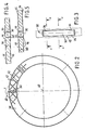
- FIG. 1
- einen Querschnitt durch den neuen Drehteller,
- FIG: 2
- eine Draufsicht auf ein, in den Drehteller eingebautes, Ringelement,
- FIG. 3
- eine vergrößerte Ansicht des Details X der Figur 2,
- FIG. 4
- einen Querschnitt längs der Linie A-A der Figur 3, und
- FIG. 5
- einen Querschnitt längs der Linie B-B der Figur 3.
Claims (10)
- Verfahren zur stufenweisen Veränderung des Drehverhaltens eines aus einer Bodenplatte und einer an dieser leicht abnehmbar zentral gelagerten Drehplatte bestehenden Drehtellers, wobei sich in einer ersten Stufe die Drehplatte (12) mit mindestens einer bodenseitigen Kreisringfläche (28, 30, 32) auf der Bodenplatte (14) abstützt, dadurch gekennzeichnet, daß in einer zweiten Stufe in mindestens eine Ringnut (36) in einer der einander zugewandten Flächen beider Platten (12, 14) ein frei drehbares Ringelement (38) eingesetzt wird, dessen deck- und bodenseitigen Gleitflächen niedrige Reibungsbeiwerte aufweisen, und dessen axial gemessene Dicke größer als die Tiefe der Ringnut (36) ist, sodaß sich die Drehplatte (12) nur über diesen, als leicht drehbarer Gleitring wirkenden Ringelement (38) auf der Bodenplatte (14) abstützt, und daß in einer dritten Stufe in Durchbrüche (48) des Ringelementes (38) Wälzkörper (50) leicht drehbar eingesetzt werden, deren wirksamer Durchmesser größer als die effektive Dicke des Ringelementes (38) ist, sodaß sich die Drehplatte (12) nur über die Wälzkörper (50) auf der Bodenplatte (14) abstützt und das Ringelement (38) nur als Führungskäfig für die Wälzkörper (50) wirkt.
- Verfahren nach Anspruch 1, dadurch gekennzeichnet, daß sich in einer ersten Stufe die Drehplatte (12) mit mindestens einer bodenseitigen Kreisringfläche (28, 30, 32) auf der Bodenplatte (14) abstützt, daß in einer zweiten Stufe in mindestens ein Paar miteinander korrespondierender Ringnuten (36) in den einander zugewandten Flächen beider Platten (12, 14) ein frei drehbares Ringelement (38) eingesetzt wird und dessen axial gemessene Dicke größer als die Summe der Tiefen beider Ringnuten (36) ist, sodaß sich die Drehplatte (12) nur über dieses, als leicht drehbarer Gleitring wirkendes Ringelement (38) auf der Bodenplatte (14) abstützt und daß in einer dritten Stufe in Durchbrüche (48) des Ringelementes (38) Wälzkörper (50) leicht drehbar eingesetzt werden, deren wirksamer Durchmesser größer als die effektive Dicke des Ringelementes (38) ist, sodaß sich die Drehplatte (12) nur über die Wälzkörper (50) auf der Bodenplatte (14) abstützt und das Ringelement (38) nur als Führungskäfig für die Wälzkörper (50) wirkt.
- Nach dem Verfahren gemäß Anspruch 1 oder 2 in seinem Dreh-verhalten veränderbarer Drehteller (10), dessen Drehplatte (12) mit einer Kreisringfläche (28, 30, 32) auf der Bodenplatte (14) drehbar abstützbar ist, dadurch gekennzeichnet, daß in mindestens einer der Platten (12, 14) eine kreisringförmige, koaxial zur Drehplatte (12) liegende, der anderen der beiden Platten (12, 14) zugewandte Ringnut (36) vorgesehen ist, in der ein leicht drehbares Ringelement (38) einsetzbar ist, dessen effektive axiale Wandstärke etwas größer als die auf die Kreisringfläche (28, 30, 32) bezogene Tiefe der Ringnut (36) ist, sodaß das Ringelement (38) geringfügig aus der Ringnut (36) herausragt und daß sich in dem Ringelement (38) mehrere in gleichen Umfangsabständen vorgesehene Durchbrüche (48) befinden, in die mindestens einige leicht drehbare Wälzkörper (50) einsetzbar sind, deren wirksamer Durchmesser geringfügig größer als die effektive Dicke des Ringelementes (38) ist.
- Drehteller nach Anspruch 3, dadurch gekennzeichnet, daß die Gleitflächen (44, 46) an schmalen, deckseitig und bodenseitig vom Ringelement (38) vorstehenden Stegen (40, 42) ausgebildet sind.
- Drehteller nach Anspruch 4, dadurch gekennzeichnet, daß die Stege (40, 42) in zwei Gruppen einander rechtwinklig kreuzender Steganordnungen orientiert sind, wobei jeweils ein Paar linear ausgerichteter Stege (40 bzw. 42) beider Gruppen radial zur Drehachse (40) der Drehplatte (12) angeordnet sind.
- Drehteller nach einem der Ansprüche 3-5, dadurch gekennzeichnet, daß die Durchbrüche (48) länglich ausgebildet und radial angeordnet sind und die Drehachse jedes zylindrisch ausgebildeten Wälzkörpers (50) mit der Radialrichtung der Durchbrüche (48) zusammenfällt.
- Drehteller nach Anspruch 3-6, dadurch gekennzeichnet, daß die Durchbrüche (48) an einem Paar einander gegenüberliegender Oberränder und an einem Paar einander gegenüberliegender Unterränder jeweils Haltelappen (52, 54) aufweisen, die den jeweiligen Wälzkörper (50) oben und unten übergreifen und diesen am Herausfallen hindern und daß die Haltelappen (52, 54) an wenigstens einem Randpaar elastisch verformbar ausgebildet sind.
- Drehteller nach einem der Ansprüche 3-7, dadurch gekennzeichnet, daß die Anzahl der Durchbrüche (48) geteilt durch die Zahl 2 eine ganze Zahl von mindestens 3 ergibt.
- Drehteller nach einem der Ansprüche 3-8, dadurch gekennzeichnet, daß die Ringnut (36) in der Drehplatte (12) vorgesehen ist.
- Drehteller nach einem der Ansprüche 3-8, dadurch gekennzeichnet, daß in der Drehplatte (12) und in der Bodenplatte (14) je eine Ringnut (36) gleichen Durchmessers und gleicher Breite ausgebildet ist und daß das Ringelement (38) in beide Ringnuten (36) eingreift und eine axiale Wandstärke geringfügig größer als die Summe der Tiefen beider Ringnuten (36) hat.
Applications Claiming Priority (2)
| Application Number | Priority Date | Filing Date | Title |
|---|---|---|---|
| DE4433853A DE4433853A1 (de) | 1994-09-22 | 1994-09-22 | Drehteller mit Stand- oder Sitzfläche für Behinderte |
| DE4433853 | 1994-09-22 |
Publications (2)
| Publication Number | Publication Date |
|---|---|
| EP0702947A1 EP0702947A1 (de) | 1996-03-27 |
| EP0702947B1 true EP0702947B1 (de) | 1999-11-24 |
Family
ID=6528909
Family Applications (1)
| Application Number | Title | Priority Date | Filing Date |
|---|---|---|---|
| EP95109775A Expired - Lifetime EP0702947B1 (de) | 1994-09-22 | 1995-06-23 | Drehteller mit Stand- oder Sitzfläche für Behinderte |
Country Status (5)
| Country | Link |
|---|---|
| EP (1) | EP0702947B1 (de) |
| JP (1) | JPH08224277A (de) |
| AT (1) | ATE186833T1 (de) |
| CA (1) | CA2158184A1 (de) |
| DE (2) | DE4433853A1 (de) |
Families Citing this family (1)
| Publication number | Priority date | Publication date | Assignee | Title |
|---|---|---|---|---|
| DE10038849C2 (de) * | 2000-08-04 | 2003-11-27 | Leonair Gmbh | Vorrichtung zum kippsicheren Umsetzen insbesondere körperbehinderter Personen |
Family Cites Families (11)
| Publication number | Priority date | Publication date | Assignee | Title |
|---|---|---|---|---|
| CH254104A (de) * | 1946-08-02 | 1948-04-15 | Raez Ammann Ida | Vorrichtung zum Drehen von Kranken auf ihrem Lager. |
| US2757388A (en) | 1953-07-28 | 1956-08-07 | Adamson Stephens Mfg Co | Bedside transfer stand |
| US2905229A (en) * | 1955-11-08 | 1959-09-22 | Raymond N Adams | Rotary stool |
| DE1989528U (de) * | 1968-04-22 | 1968-07-18 | Fritz Zur Heide | Untergestell fuer sitzmoebel. |
| US3637185A (en) * | 1969-05-21 | 1972-01-25 | Seng Co The | Self-orienting revolving fixture |
| GB2214424A (en) * | 1988-01-28 | 1989-09-06 | Alexander Feldmann | Rotating seat device |
| DE3835532C1 (de) * | 1988-10-19 | 1990-02-15 | Peter 7989 Eisenharz De Schmidt | |
| CA2015353A1 (en) * | 1989-12-04 | 1991-06-04 | Dennis J. Gryp | Swivel seat, especially for vehicles |
| US5078451A (en) * | 1990-08-16 | 1992-01-07 | Sobel David J | Portable rotatable beach chaise lounge |
| US5281017A (en) * | 1992-05-26 | 1994-01-25 | Geiss Ii Michael J | Wheelchair accessible desk/lift |
| US5311622A (en) * | 1992-07-06 | 1994-05-17 | Allen Roy H | Patient handling device |
-
1994
- 1994-09-22 DE DE4433853A patent/DE4433853A1/de not_active Withdrawn
-
1995
- 1995-06-23 AT AT95109775T patent/ATE186833T1/de not_active IP Right Cessation
- 1995-06-23 DE DE59507282T patent/DE59507282D1/de not_active Expired - Fee Related
- 1995-06-23 EP EP95109775A patent/EP0702947B1/de not_active Expired - Lifetime
- 1995-09-13 CA CA002158184A patent/CA2158184A1/en not_active Abandoned
- 1995-09-22 JP JP7269237A patent/JPH08224277A/ja active Pending
Also Published As
| Publication number | Publication date |
|---|---|
| DE59507282D1 (de) | 1999-12-30 |
| JPH08224277A (ja) | 1996-09-03 |
| ATE186833T1 (de) | 1999-12-15 |
| EP0702947A1 (de) | 1996-03-27 |
| DE4433853A1 (de) | 1996-03-28 |
| CA2158184A1 (en) | 1996-03-23 |
Similar Documents
| Publication | Publication Date | Title |
|---|---|---|
| DE2831044C2 (de) | Gleichlaufgelenkkupplung | |
| EP0904751A1 (de) | Rohrförmiger Stützkörper zum Überbrücken zweier Wirbel | |
| DE3618496A1 (de) | Riementrieb und dafuer vorgesehenes antriebselement | |
| DE3702530A1 (de) | Drehlageranordnung | |
| CH672823A5 (de) | ||
| DE19841016A1 (de) | Drehmomentbegrenzer | |
| DE202018102210U1 (de) | Verstellmechanismus und Hebevorrichtung, welche den Verstellmechanismus umfasst | |
| EP0974773A2 (de) | Wellgetriebe mit verbesserten Pulsator | |
| DE112004002814B4 (de) | Zusammengesetztes Wälzlager | |
| DE3014860A1 (de) | Uebersetzungsgetriebe | |
| DE10015957A1 (de) | Wälzaufbau | |
| EP2553281A1 (de) | Lageranordnung mit mindestens zwei relativ zu einander drehbaren teilen | |
| DE3419450C3 (de) | Linearrollenlagerung | |
| EP2551537A1 (de) | Losradlagerung für ein Kraftfahrzeuggetriebe | |
| EP0702947A1 (de) | Drehteller mit Stand- oder Sitzfläche für Behinderte | |
| DE102009034020A1 (de) | Wälzlager | |
| DE2440789C3 (de) | Drucklager für eine Laufrolle einer Schiebetür | |
| EP0784323B1 (de) | Gehäuse | |
| DE1204043B (de) | Grenzkraftkupplung zur UEbertragung kleiner Leistungen in feinmechanischen oder elektro-technischen Geraeten | |
| DE2747400C2 (de) | Hydrodynamisches Axiallager | |
| DE10124267B4 (de) | Hydraulisches Pressgerät | |
| DE60205337T2 (de) | Fördervorrichtung, Rollentransportvorrichtung und eine Fördereinheit | |
| EP3798457B1 (de) | Montagewerkzeug und verfahren zum montieren eines lagers mit diesem montagewerkzeug | |
| DE19824069A1 (de) | Getriebe | |
| EP3550092A1 (de) | Höhenverstellbares stelzlager |
Legal Events
| Date | Code | Title | Description |
|---|---|---|---|
| PUAI | Public reference made under article 153(3) epc to a published international application that has entered the european phase |
Free format text: ORIGINAL CODE: 0009012 |
|
| AK | Designated contracting states |
Kind code of ref document: A1 Designated state(s): AT BE CH DE DK ES FR GB GR IE IT LI LU NL PT SE |
|
| 17P | Request for examination filed |
Effective date: 19960205 |
|
| 17Q | First examination report despatched |
Effective date: 19981126 |
|
| GRAG | Despatch of communication of intention to grant |
Free format text: ORIGINAL CODE: EPIDOS AGRA |
|
| GRAG | Despatch of communication of intention to grant |
Free format text: ORIGINAL CODE: EPIDOS AGRA |
|
| GRAH | Despatch of communication of intention to grant a patent |
Free format text: ORIGINAL CODE: EPIDOS IGRA |
|
| GRAH | Despatch of communication of intention to grant a patent |
Free format text: ORIGINAL CODE: EPIDOS IGRA |
|
| GRAA | (expected) grant |
Free format text: ORIGINAL CODE: 0009210 |
|
| AK | Designated contracting states |
Kind code of ref document: B1 Designated state(s): AT BE CH DE DK ES FR GB GR IE IT LI LU NL PT SE |
|
| PG25 | Lapsed in a contracting state [announced via postgrant information from national office to epo] |
Ref country code: SE Free format text: THE PATENT HAS BEEN ANNULLED BY A DECISION OF A NATIONAL AUTHORITY Effective date: 19991124 Ref country code: NL Free format text: LAPSE BECAUSE OF FAILURE TO SUBMIT A TRANSLATION OF THE DESCRIPTION OR TO PAY THE FEE WITHIN THE PRESCRIBED TIME-LIMIT Effective date: 19991124 Ref country code: IT Free format text: LAPSE BECAUSE OF FAILURE TO SUBMIT A TRANSLATION OF THE DESCRIPTION OR TO PAY THE FEE WITHIN THE PRE;WARNING: LAPSES OF ITALIAN PATENTS WITH EFFECTIVE DATE BEFORE 2007 MAY HAVE OCCURRED AT ANY TIME BEFORE 2007. THE CORRECT EFFECTIVE DATE MAY BE DIFFERENT FROM THE ONE RECORDED.SCRIBED TIME-LIMIT Effective date: 19991124 Ref country code: GR Free format text: LAPSE BECAUSE OF NON-PAYMENT OF DUE FEES Effective date: 19991124 Ref country code: GB Free format text: LAPSE BECAUSE OF FAILURE TO SUBMIT A TRANSLATION OF THE DESCRIPTION OR TO PAY THE FEE WITHIN THE PRESCRIBED TIME-LIMIT Effective date: 19991124 Ref country code: FR Free format text: LAPSE BECAUSE OF FAILURE TO SUBMIT A TRANSLATION OF THE DESCRIPTION OR TO PAY THE FEE WITHIN THE PRESCRIBED TIME-LIMIT Effective date: 19991124 Ref country code: ES Free format text: THE PATENT HAS BEEN ANNULLED BY A DECISION OF A NATIONAL AUTHORITY Effective date: 19991124 |
|
| REF | Corresponds to: |
Ref document number: 186833 Country of ref document: AT Date of ref document: 19991215 Kind code of ref document: T |
|
| REG | Reference to a national code |
Ref country code: CH Ref legal event code: EP |
|
| REF | Corresponds to: |
Ref document number: 59507282 Country of ref document: DE Date of ref document: 19991230 |
|
| REG | Reference to a national code |
Ref country code: IE Ref legal event code: FG4D Free format text: GERMAN |
|
| PG25 | Lapsed in a contracting state [announced via postgrant information from national office to epo] |
Ref country code: PT Free format text: LAPSE BECAUSE OF FAILURE TO SUBMIT A TRANSLATION OF THE DESCRIPTION OR TO PAY THE FEE WITHIN THE PRESCRIBED TIME-LIMIT Effective date: 20000224 Ref country code: DK Free format text: LAPSE BECAUSE OF FAILURE TO SUBMIT A TRANSLATION OF THE DESCRIPTION OR TO PAY THE FEE WITHIN THE PRESCRIBED TIME-LIMIT Effective date: 20000224 |
|
| EN | Fr: translation not filed | ||
| NLV1 | Nl: lapsed or annulled due to failure to fulfill the requirements of art. 29p and 29m of the patents act | ||
| GBV | Gb: ep patent (uk) treated as always having been void in accordance with gb section 77(7)/1977 [no translation filed] |
Effective date: 19991124 |
|
| PG25 | Lapsed in a contracting state [announced via postgrant information from national office to epo] |
Ref country code: LU Free format text: LAPSE BECAUSE OF NON-PAYMENT OF DUE FEES Effective date: 20000623 Ref country code: AT Free format text: LAPSE BECAUSE OF NON-PAYMENT OF DUE FEES Effective date: 20000623 |
|
| PG25 | Lapsed in a contracting state [announced via postgrant information from national office to epo] |
Ref country code: LI Free format text: LAPSE BECAUSE OF NON-PAYMENT OF DUE FEES Effective date: 20000630 Ref country code: CH Free format text: LAPSE BECAUSE OF NON-PAYMENT OF DUE FEES Effective date: 20000630 Ref country code: BE Free format text: LAPSE BECAUSE OF NON-PAYMENT OF DUE FEES Effective date: 20000630 |
|
| PG25 | Lapsed in a contracting state [announced via postgrant information from national office to epo] |
Ref country code: IE Free format text: LAPSE BECAUSE OF NON-PAYMENT OF DUE FEES Effective date: 20000720 |
|
| REG | Reference to a national code |
Ref country code: IE Ref legal event code: FD4D |
|
| PLBE | No opposition filed within time limit |
Free format text: ORIGINAL CODE: 0009261 |
|
| STAA | Information on the status of an ep patent application or granted ep patent |
Free format text: STATUS: NO OPPOSITION FILED WITHIN TIME LIMIT |
|
| 26N | No opposition filed | ||
| BERE | Be: lapsed |
Owner name: SCHMIDT & LENHARDT G.M.B.H. & CO. OHG Effective date: 20000630 |
|
| REG | Reference to a national code |
Ref country code: CH Ref legal event code: PL |
|
| PGFP | Annual fee paid to national office [announced via postgrant information from national office to epo] |
Ref country code: DE Payment date: 20040823 Year of fee payment: 10 |
|
| PG25 | Lapsed in a contracting state [announced via postgrant information from national office to epo] |
Ref country code: DE Free format text: LAPSE BECAUSE OF NON-PAYMENT OF DUE FEES Effective date: 20060103 |