EP0702284B1 - Timepiece having light transmission type display plate - Google Patents
Timepiece having light transmission type display plate Download PDFInfo
- Publication number
- EP0702284B1 EP0702284B1 EP95907872A EP95907872A EP0702284B1 EP 0702284 B1 EP0702284 B1 EP 0702284B1 EP 95907872 A EP95907872 A EP 95907872A EP 95907872 A EP95907872 A EP 95907872A EP 0702284 B1 EP0702284 B1 EP 0702284B1
- Authority
- EP
- European Patent Office
- Prior art keywords
- plate
- light transmitting
- type display
- transmitting type
- display plate
- Prior art date
- Legal status (The legal status is an assumption and is not a legal conclusion. Google has not performed a legal analysis and makes no representation as to the accuracy of the status listed.)
- Expired - Lifetime
Links
Images


Classifications
-
- G—PHYSICS
- G04—HOROLOGY
- G04C—ELECTROMECHANICAL CLOCKS OR WATCHES
- G04C10/00—Arrangements of electric power supplies in time pieces
- G04C10/02—Arrangements of electric power supplies in time pieces the power supply being a radioactive or photovoltaic source
-
- G—PHYSICS
- G04—HOROLOGY
- G04B—MECHANICALLY-DRIVEN CLOCKS OR WATCHES; MECHANICAL PARTS OF CLOCKS OR WATCHES IN GENERAL; TIME PIECES USING THE POSITION OF THE SUN, MOON OR STARS
- G04B19/00—Indicating the time by visual means
- G04B19/06—Dials
- G04B19/12—Selection of materials for dials or graduations markings
-
- G—PHYSICS
- G04—HOROLOGY
- G04B—MECHANICALLY-DRIVEN CLOCKS OR WATCHES; MECHANICAL PARTS OF CLOCKS OR WATCHES IN GENERAL; TIME PIECES USING THE POSITION OF THE SUN, MOON OR STARS
- G04B19/00—Indicating the time by visual means
- G04B19/06—Dials
- G04B19/14—Fastening the dials to the clock or watch plates
-
- G—PHYSICS
- G04—HOROLOGY
- G04B—MECHANICALLY-DRIVEN CLOCKS OR WATCHES; MECHANICAL PARTS OF CLOCKS OR WATCHES IN GENERAL; TIME PIECES USING THE POSITION OF THE SUN, MOON OR STARS
- G04B19/00—Indicating the time by visual means
- G04B19/30—Illumination of dials or hands
-
- G—PHYSICS
- G04—HOROLOGY
- G04C—ELECTROMECHANICAL CLOCKS OR WATCHES
- G04C17/00—Indicating the time optically by electric means
-
- G—PHYSICS
- G04—HOROLOGY
- G04G—ELECTRONIC TIME-PIECES
- G04G9/00—Visual time or date indication means
- G04G9/0023—Visual time or date indication means by light valves in general
- G04G9/0029—Details
- G04G9/0035—Details constructional
- G04G9/0041—Illumination devices
Definitions
- the present invention relates to a watch comprising a cell made up of a light-emitting member or a light-absorbing member laminated onto a movement, and a support member onto which the cell is fixed.
- Such a watch is known from the FR-A-2 212 573 whereby there are mounted several layers between the hands and the movement to improve the decorative effect.
- the said members can nowadays be realised with an EL (electroluminescence) element, a solar panel or the like.
- a conventional structure with a display plate and a light diffusion plate used together with an EL element or a lamp or a light emitting diode, fixed to the movement, is disclosed, for example, in Japanese Laid Open Patent Application (kokai) No. 84886/1993.
- the fixing structure has a transparent display plate and a light diffusing plate having almost the same shape as the transparent display plate and positioned on the bottom surface of the transparent display plate, the both fixed to a support frame using double-sided adhesive tape.
- This type of conventional fixing structure has a superior feature inasmuch as it is possible to easily fix the light diffusing plate and the transparent display plate to the support frame.
- the structure has a disadvantage in that the positioning is unstable because it is not possible to position the transparent display plate and the support frame. Therefore, the positioning depends, in the final analysis, on a method in which an operator must make a visual judgment.
- examples of a fixing structure by which solar cells and the display plate are fixed to the movement include, for example, a structure wherein the color of the solar cell itself is used to full advantage by exposing the solar cell, a structure wherein the time characters or the like are printed directly onto the surface of the solar cell, or a structure wherein a transparent seal onto which an ornament has been printed is affixed to the solar cell. These structures are fixed by a solar cell fixing member.
- FIG 28 is an outline of a sectional view showing the case in which a transparent seal is used.
- a transparent seal 151 on which an ornament has been printed, is fixed by being affixed to the upper surface of a solar cell 140, except for a shaft section 152 which supports the hands of the watch.
- the solar cell 140 to which is affixed the transparent seal 151 is securely connected to a movement 110 by means of a solar cell fixing member 153.
- Figure 29 shows a watch with a solar cell attached which uses a parting plate.
- Figure 29(a) is an outline of a sectional view and Figure 29(b) is a plan view.
- a fixing pin 154a on a parting plate 154 on which an ornament is printed engages a plurality of holes 110a set in a flange section of the movement 110, to incorporate the parting plate 154 and interpose the solar cell 140 between the parting plate 154 and the movement 110, thereby fixing the solar cell 140 to the movement 110.
- Figure 30 is an outline of a sectional view showing the case where a light transmitting display plate is maintained by an outer casing.
- a light transmitting display plate 160 is incorporated at the same time as an external casing 155 is mounted on the completed movement 110 incorporating the solar cell 140 and a solar cell fixing member 153 which positions the solar cell 140.
- the light transmitting display plate 160 is fixed by the external casing 155 when the watch is completely assembled.
- the structure shown in Figure 30 is unstable in the interval from when the hands are attached until the casing is mounted inasmuch as the position of the light transmitting display plate has not been decided. There is therefore the drawback of extremely poor workability and handling.
- an object of the present invention is to provide, with due consideration to the drawbacks of such conventional watches, a watch with a light transmitting display plate wherein, by positioning the light transmitting display plate on the cell which is an EL element or a solar cell or the like, considerable product variety is obtained, and anyone can position the transmitting display plate using a simple operation, and in addition, the operations of mounting and dismounting the transmitting display plate relative to the support frame are easily performed.
- Figure 31 is a sectional view showing a display section described in US Patent No. 4,775,964.
- a symbol 121 illustrating the time or the like referred to as time characters, is formed directly on the upper surface of an EL element 130 formed on the upper surface of a movement 110 by a printing method or the like.
- the appearance of the display section is poor so that the value of the goods decreases.
- the color of the display section is limited to the color of the EL element 130 (generally a cream color).
- a display section in which this problem is eliminated is proposed in Japanese Laid Open Patent Application No. 291192/1992.
- a sectional view of this display section is shown in Figure 32.
- a metal layer 131 and a transparent display plate 120 are formed as successive laminations on the EL element 130.
- the symbol 121 illustrating the time is provided on the transparent display plate 120.
- the metal layer 131 is formed by coating a metal such as gold or silver or the like on the EL element 130.
- the transparent display plate 120 is mounted directly on the EL element 130 via the metal layer 131.
- the color of the display section is determined by the color of the EL element 130 and the metal layer 131 when the EL element 130 is emitting light, and by the color of the metal layer 131 when the EL element 130 is not emitting light. Freedom in color is therefore insufficient.
- the transparent display plate 120 and the EL element 130 are held in close contact via the metal layer 131. Therefore, a Newton ring or the like is produced by the refraction of the light at the surface of the junction. This causes the presentation to be worsened.
- the display section of a watch using a solar cell such as shown in Figure 30 also generates a Newton ring or the like because the transparent plate 160 is positioned directly on the upper surface of the solar cell 140, so that the converging efficiency is poor.
- another object of the present invention is to provide a watch with a light transmitting type display plate which can be easily changed by positioning a transparent or opaque display plate on the upper surface of the EL element or the solar cell at a specified gap, thereby preventing the development of a Newton ring or the like and providing superior converging efficiency, excellent appearance, sufficient freedom for the color, and a clear display section.
- a watch comprising a cell made up of a light-emitting member, such as an EL element, or of a light-absorbing member, such as a solar cell, is laminated onto a movement and fixed to a support member, whereby said watch is characterized in that it has a light transmitting type display plate wherein the light transmitting type display plate is arranged above the cell which is a light-emitting member or a light-absorbing member and fixed to the support member by the engagement of a positioning section formed on the light transmitting type display plate with a positioning section formed on the support member, and in that the positioning section of the light transmitting type display plate is a projecting section extending from the outer periphery of the light transmitting type display plate and in that the positioning section of the support member is an indented section formed in the support member.
- a light transmitting type display plate wherein the light transmitting type display plate is arranged above the cell which is a light-emitting member or a light-absorbing member and fixed to the support member by the engagement of
- the display section of the watch can be easily fixed, and the workability during assembly and disassembly can be considerably improved.
- the light transmitting type display plate is positioned to form a gap at the cell made up of the EL element or the solar cell to prevent light interference fringes of a Newton ring or the like.
- This gap is formed by providing an irregularity on the contact surface of the light transmitting type display plate and/or the cell or by providing a spacer at the outer peripheral section between the light transmitting type display plate and the cell.
- the display plate can be changed and various colors and ornamentations can be enjoyed.
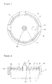
- Figure 1 is a plan view of a first embodiment of the present invention, with the outer casing of the watch omitted.
- Figure 2 is an outline of a sectional view of the first embodiment of the present invention, with the outer casing of the watch omitted.
- Figure 3 is an outline of a sectional view of a second embodiment of the present invention, with the outer casing of the watch omitted.
- Figure 4 is an outline of a sectional view of a third embodiment of the present invention, with the outer casing of the watch omitted.
- Figure 5 is an outline of a sectional view of a fourth embodiment of the present invention, with the outer casing of the watch omitted.
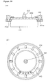
- Figure 6 is a plan view of a fifth embodiment of the present invention, with the outer casing of the watch omitted.
- Figure 7 is an enlarged plan view of the principal parts of the fifth embodiment of the present invention, with the outer casing of the watch omitted.
- Figure 8 is an enlarged side elevation of the principal parts of the fifth embodiment of the present invention, with the outer casing of the watch omitted.
- Figure 9 is a plan view of a sixth embodiment of the present invention, with the outer casing of the watch omitted.
- Figure 10 is an enlarged plan view of the principal parts of the sixth embodiment of the present invention, with the outer casing of the watch omitted.
- Figure 11 is an enlarged side elevation of the principal parts of the sixth embodiment of the present invention, with the outer casing of the watch omitted.
- Figure 12 is a plan view of a seventh embodiment of the present invention, with the outer casing of the watch omitted.
- Figure 13 is an outline of a sectional view of an eighth embodiment of the present invention, with the outer casing of the watch omitted.
- Figure 14 is a plan view of the eighth embodiment of the present invention, with the outer casing of the watch omitted.
- Figure 15 is an outline of expanded sectional view of a completed watch.
- Figure 16 is a plan view of a ninth embodiment of the present invention, with the outer casing of the watch omitted.
- Figure 17 is an outline of a sectional view of the ninth embodiment of the present invention, with the outer casing of the watch omitted.
- Figure 18 is a plan view of a tenth embodiment of the present invention, with the outer casing of the watch omitted.
- Figure 19 is a partial plan view of an eleventh embodiment of the present invention.
- Figure 20 is view taken along the section A - A shown in Figure 19.
- Figure 21 is view taken along the section B - B shown in Figure 19.
- Figure 22 is a plan view showing an example of a pattern plate set into a center-hole of a metal dial, with the outer casing of the watch omitted.
- Figure 23 is an outline of a sectional view of a twelfth embodiment of the present invention, with the outer casing of the watch omitted.
- Figure 24 is an outline of a sectional view of a thirteenth embodiment of the present invention, with the outer casing of the watch omitted.
- Figure 25 is an outline of a sectional view of a fourteenth embodiment of the present invention, with the outer casing of the watch omitted.
- Figure 26 is an outline of a sectional view of a fifteenth embodiment of the present invention, with the outer casing of the watch omitted.
- Figure 27 is an outline of a sectional view of a sixteenth embodiment of the present invention, with the outer casing of the watch omitted.
- Figure 28 is an outline of a sectional view of a first conventional example, with the outer casing of the watch omitted.
- Figure 29(a) is an outline of a sectional view of a second conventional example.
- Figure 29(b) is a plan of a sectional view of the second conventional example.
- Figure 30 is an outline of a sectional view of the principal parts of the third conventional example.
- Figure 31 is an outline of a sectional view of a fourth conventional example, with the outer casing of the watch omitted.
- Figure 32 is an outline of a sectional view of a fifth conventional example, with the outer casing of the watch omitted.
- Figure 1 and Figure 2 are a plan view and an outline of a sectional view respectively of a first embodiment of the present invention, with the outer casing of the watch omitted.
- a cell 2 which is formed by a light emitting member such as an EL element or the like, or a light absorbing member such as a solar cell or the like, is mounted on the upper surface of a movement 1.
- the cell 2 and the movement 1 have almost the same plane shape, and are provided with a hole 2a in the central section through which a shaft 3 for carrying the hands extends.
- a support member 4 is formed from plastic in the shape of a ring.
- a flange 4a is formed on the upper part of the support member 4, projecting inward.
- Indented sections 4b as positioning sections are formed as a groove from the inside to the outside on the upper surface of the flange 4a of the support member 4.
- the indented sections 4b are formed in three locations on the flange 4a.
- the indented sections 4b at two of these three locations are opposedly positioned 180° apart.
- the indented section 4b is formed at the remaining location more or less offset from a location halfway between the two opposing indented sections 4b.
- a light transmitting type display plate 5 is formed by printing or coating an ornament such as a dial, a pet name, numbers, a pattern, or the like on a transparent or semitransparent plate in the form of a thin plate made from acryl, polycarbonate, ceramic, or the like.
- a transparent plate 5 (hereinafter this term is used to include both a transparent and a semitransparent plate), which forms the light transmitting type display plate, is provided with a hole 5a in the central section through which the shaft 3 for carrying the hands extends.
- Projecting sections 5b are formed as positioning sections on the flange section projecting toward the outside in three locations corresponding to the indented sections 4b formed on the flange 4a of the support member 4.
- the watch with this configuration is assembled as follows.
- the transparent plate 5 is mounted on the upper surface of the cell 2.
- a spacer 6 formed in the shape of a ring along the outer periphery of the transparent plate 5 is interposed between the cell 2 and the transparent plate 5 so that a gap 7 is formed between the cell 2 and the transparent plate 5 to prevent the production of light interference fringes such as a Newton ring or the like between the two.
- the gap 7 between the cell 2 and the transparent plate 5 can also be formed simply by providing an elevated bottom surface of the indented section 4b of the support member 4 (see the left side section of Figure 2).
- the positioning at this time can be visually performed very easily and accurately by an operator if the positions of the projecting section 5b and the indented section 4b respectively are in good conformation.
- the transparent plate 5 is pressed downward, and is firmly fixed to the top surface of the cell 2 through the spacer 6.
- the fixing operation can be easily performed when the dimensions of the transparent plate 5 and the support member 4 are set so that a gap 8 is produced in the diametrical direction between the outer periphery of the section other than the projecting section 5b of the transparent plate 5, which is the light transmitting type display plate, and the inner periphery of the support section 4, even when there is a slight dimensional error in the two.
- the transparent plate 5 which is the light transmitting type display plate, can easily be fixed to the support member 4 by the engagement of the indented sections 4b and the projecting sections 5b. Furthermore, because the indented sections 4b and the projecting sections 5b are each formed in three locations, the engaged transparent plate 5 will not rotate or slip from the groove even when force is applied in the horizontal direction.
- the transparent plate 5 can be easily removed from the support member 4.
- at least one of the indented sections 4b and the projecting sections 5b slightly offset so as to be asymmetrical for example, in the case of two, positioned at 12 o'clock and at 7 o'clock
- the directional matching and the positioning of the transparent plate 5, which is the light transmitting type display plate, with respect to the support plate 4 is easier.
- Figure 3 is an outline of a sectional view of a second embodiment of the present invention, with the outer casing of the watch omitted.
- the watch of this second embodiment uses a metal plate, which is surface treated by plating or coating, as a light transmitting type display plate 50.
- a metal plate which is surface treated by plating or coating, as a light transmitting type display plate 50.
- One part or all of the ornamental sections such as the dial, numbers, patterns, and the like is formed by means of a hole 50a through which the shaft supporting the hands penetrates and through-holes 51, and light is transmitted through the hole 50a and the through-holes 51.
- the cell 2 is an EL element
- the light from the EL element passes through the hole 50a and the through-holes 51 and is transmitted to the surface of the display plate.
- the cell 2 is a solar cell
- sunlight passes through the hole 50a and the through-holes 51 and is transmitted to the solar cell on the lower surface of the display plate.
- the light transmitting type display plate is formed as the metal plate 50 in this manner, a large area is provided to the through-holes 51 and the hole 50a on which the ornamental section is formed.
- the configuration is the same as for the first embodiment.
- the light transmitting type display plate is formed as the metal plate 50
- the metal plate 50 when the metal plate 50 is mounted on the upper surface of the cell 2, it is not necessary to provide a gap between the metal plate 50 and the cell 2, therefore it is not necessary to interpose a spacer between the two. Accordingly, the operating procedure to fix the metal plate 50, which is the light transmitting type display plate, to the upper surface of the cell 2 is the same as for the first embodiment with the exception of the operation to interpose the spacer.
- the light transmitting type display plate may also be formed by laminating the transparent plate 5 and the metal plate 50, and, as in a third embodiment shown in Figure 4, the metal plate 50 is laminated onto the transparent plate 5 as explained for the first embodiment, or as in a fourth embodiment shown in Figure 5, the transparent plate 5 is laminated onto the metal plate 50 as explained for the second embodiment.
- the projecting sections 5b and 50b project to the outer periphery of the transparent plate 5 and the metal plate 50 respectively, and engage the indented sections 4b of the support member 4 to fix the plates.
- Figure 6 to Figure 8 are a plan view, an enlarged plan view of the principal parts, and an enlarged side elevation of the principal parts respectively of a fifth embodiment of the present invention, with the outer casing of the watch omitted.
- notched sections 5c which are outward-facing openings almost in the center of the projecting sections 5b, the positioning sections of the transparent plate 5 as the light transmitting type display plate, and which extend from the upper surface to the lower surface of the projecting sections 5b.
- projections 4c which engage the notched sections 5c project from the indented sections 4b of the support member 4 almost at the center.
- the notched sections 5c of the projecting sections 5b are deep, and a gap is formed between the projections 4c. Specifically, by forming a gap 8a similar to the gap 8 between the outer periphery of the transparent plate 5 and the inner periphery of the support member 4, the transparent plate 5 is easily fixed in the same manner as in the above-described case.
- the transparent plate 5, which is the light transmitting type display plate is solidly fixed to the support member 4c by the engagement of the notched section 5c of the projecting section 5b with the projections 4c of the indented section 4b. Accordingly, as shown in Figure 7 and Figure 8, the width of the projecting section 5b is less than the width of the indented section 4b, so that it is possible to form a gap 8b between them. As a result, an unsatisfactory engagement does not occur even when there is a slight dimensional error between the projecting section 5b and the indented section 4b, and an easier fixing operation is possible along with the presence of the previously described gaps 8, 8a.
- the fifth embodiment can be applied to the case where the light transmitting type display plate is made up of the metal plate 50 as in the case of the second embodiment or to the case where the transparent plate 5 and the metal plate 50 are laminated as in the cases of the third and fourth embodiments.
- the projecting sections in which the notched sections 5c, 50c are formed and the indented sections in which the projections 4c are formed can also be part of the projecting sections 5b, 50b and the indented section 4b, respectively.
- the number and position can be suitably selected depending on the number of the positioning sections.
- Figure 9 to Figure 11 are a plan view, an enlarged plan view of the principal parts, and an enlarged side elevation of the principal parts respectively of a sixth embodiment of the present invention, with the outer casing of the watch omitted.
- the watch of this sixth embodiment has a metal plate 50 laminated onto the upper surface of the transparent plate 5 shown in the third embodiment as the light transmitting type display plate and is an example wherein the following design is adopted in the positioning section of a light transmitting type display plate. That is, the projecting section 5b of the transparent plate 5 is provided with a notched section 5c almost in the center of the projecting section 5b, similar to the positioning section in the fifth embodiment, and is formed to engage the projection 4c of the indented section 4b of the support member.
- a projecting section 50b is formed from two projecting leaves 50d and a notch is made in the root section facing the projecting leaves 50d.
- the projecting leaves 50d are made to bend inward from the elasticity of the metal.
- a small through hole 50e is formed in the tip sections of each of the two projecting leaves 50d.
- the light transmitting type display plate To fix the light transmitting type display plate in this case, first, with the notched section 5c of each projecting section 5b of the transparent plate 5 engaging the projection 4c of each indented section 4b of the support member 4, the projecting sections 5b are caused to engage the indented sections 4b so that the transparent plate 5 is fixed to the support member 4. Next, the two projecting leaves 50d of each projecting section 50b of the metal plate 50 are pushed in each indented section 4b of the support member 4 while bending inward, so that the metal plate 50 is fixed to the support member 4 which is laminated onto the upper part of the transparent plate 5.
- the light transmitting type display plate made up of the transparent plate 5 and the metal plate 50 is integrally fixed to and supported on the support plate 4.
- the projecting leaves 50d are solidly fixed in the indented sections 4b because the outer surfaces of the projecting leaves 50d apply outward pressure to the inside surfaces of the indented sections 4b.
- the projecting leaves 50d are pressed upward using a pair of tweezers or the like, to remove each of the pressed-in projecting leaves 50d from the indented section 4b.
- the removal of the metal plate 50 is made even easier by inserting the ends of the tweezers into the holes 50e in each of the projecting leaves 50d to squeezing them, thereby bending the indented section 4b inward to break the engagement of the projecting leaves 50d.
- Figure 12 is a plan view of a seventh embodiment of the present invention, with the outer casing of the watch omitted.
- the watch of the seventh embodiment represents a further improvement over the sixth embodiment.
- the projecting sections 50b of the metal plate 50 two projecting leaves 50d are formed on two corresponding and opposed projecting sections 50b, as in the sixth embodiment, and a notch 5c is formed almost at the center of the remaining projecting sections 50b, as in the fifth embodiment.
- the shapes of the two projecting leaf type projecting sections and the one remaining notched type projecting section are clearly different. Therefore if an assembly operator knows which of the indented sections of the support member 4 is engaged by the notched projecting section, no mistake is made in the corresponding relationship of the indented sections 4b and the projecting sections 50b, so that it is possible to quickly engage and fix the metal plate 50 in the support member 4.
- the number and positions of the projecting leaf type projecting sections and the notched type projecting sections can be suitably changed according to the number of positioning sections provided in the metal plate 50, specifically, the number of projecting sections.
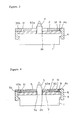
- FIG 13 and Figure 14 are a sectional view and a plan view respectively of an eighth embodiment of the present invention, with the outer casing of the watch omitted.
- This watch of the eighth embodiment has a configuration which uses a solar cell as the cell 2 and the transparent plate 5 as the light transmitting type display plate.
- the solar cell 2 is positioned on the upper surface of the movement 1 by means of a positioning pin (not shown in the drawing) provided on the hands shaft 3 side of the movement 1. Then, the solar cell 2 is interposedly fixed on the movement 1 by the support member 4. A ring-shaped heat application sheet 6a is applied by pressure to the upper surface of the solar cell 2. The projecting section 5b formed on the outer periphery of the transparent plate 5 is fixed by being lightly pressed into the indented section 4b formed on the support member 4. In addition, the heat application sheet 6a and the circuit substrate 9 are connected by a connecting spring 9a.
- a gap 8 is provided between the outer peripheral section other than the projecting section 5b of the transparent plate 5 and the outer peripheral section other than the indented section 4b of the support member 4, so that deformation from a variation in dimensions is prevented during assembly.
- a sloping section 4d is provided in the indented section 4b of the support member 4 to allow smooth incorporation of the transparent plate 5.
- the sloping section 4d may also be provided on the bottom surface of the projecting section 5b of the transparent plate 5, not on the solar cell fixing member, or may be provided on both of these.
- the ornamental transparent plate 5 is arranged on the upper surface of the heat application sheet 6a using the heat application sheet 6a affixed to the light-receiving surface of the solar cell 2 as a spacer.
- a gap 7 as thick as the heat application sheet 6a is ensured between the transparent plate 5 and the solar cell 2, preventing the formation of a Newton ring at the junction of the transparent plate 5 and the solar cell 2, so that good converging efficiency is obtained.
- a single member can therefore serve double duty as a heat application sheet and a spacer.
- This configuration can be applied even in the case where a light transmitting type display plate which has a metal plate laminated onto the upper surface of a transparent plate is used.
- Figure 15 is an outline of a sectional view of a completed watch.
- the integrated completed movement is levelly inserted into an outer casing 30 as far as the transparent plate 5. Accordingly, the floating of the transparent plate 5 in the cross-sectional direction is controlled by the outer casing 30.
- This structure in which the support member and the light transmitting type display plate are supported by the outer casing can be applied in the above-mentioned first to eighth embodiments.
- Figure 16 is a plan view and Figure 17 is an outline of a sectional view of a ninth embodiment of the present invention, with the outer casing of the watch omitted.
- the transparent plate 5 which is the light transmitting type display plate is laminated directly onto the upper surface of the cell 2 formed from an EL element or the like.
- An irregular section 7a is provided on the interface of the transparent plate 5 and the cell 2, and the gap 7 is formed between the cell 2 and the transparent plate 5 by the irregular section 7a.
- the irregular section 7a gives a pattern to the light transmitting type display plate, the design characteristics are improved.
- the gap 7 prevents the production of light interference fringes such as a Newton ring or the like, there is no decrease in the commercial value due to light interference fringes.
- the irregular section 7a needs not be only on the lower surface of the transparent plate 5 but may be provided on the surface on the upper surface of the cell 2 where it contacts the transparent plate 5, and may also be provided on both the surfaces where the transparent plate and the cell contact each other.
- the shape, size, and roughness of the irregular section 7a are optional.
- the irregularity may be like a pear-skin (sprinkled) lacquer.
- the irregular section 7a may be formed on either part or all of the lower surface of the transparent plate 5, or on part or all of the upper surface of the cell.
- the shape of the irregular section 7a is optional.
- the cross-section of the irregular shape may be triangular, as shown in Figure 17, or may be another shape such as, for example, rectangular or circular.
- the shape of the irregular section 7a may also be uniform, as shown in Figure 17, or may be a mixture of a number of different shapes.
- the irregular section may also be shaped as a character or symbol or the like for showing the time.
- This plate 5 may be transparent or colored, but it must be capable of transmitting light of the EL element.
- the entire light transmitting type display plate may be one color or may be made up of a number of different colored regions.
- the ornamental section consisting of the dial, numbers, pattern and the like is directly printed on the transparent plate 5, or formed to provide the irregularity. It is possible to display the ornamental section three-dimensionally in this manner.
- Figure 18 is a plan view of a tenth embodiment of the present invention, with the outer casing of the watch omitted.
- This embodiment is constructed so that the spacer 6 is formed over the entire periphery or on one part of the lower surface of the outer periphery of the transparent plate 5, and integrally with the transparent plate 5.
- the spacer 6 is formed over the entire periphery or on one part of the lower surface of the outer periphery of the transparent plate 5, and integrally with the transparent plate 5.
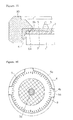
- Figures 19 to 21 are a partial plan view, a view taken along the section A-A, and a view taken along the section B-B respectively of the main part of an eleventh embodiment of the present invention.
- a projection 1a is provided integrally on the upper surface of the movement 1 as a spacer, and the cell 2 is fixedly supported on the outer casing 30 through a cell support frame 41.
- the transparent plate 5 formed as the light transmitting type display plate is fixedly supported directly by the outer casing 30.
- the cell 2 slightly smaller in diameter than the movement 1 and with a part cut out to correspond to the projecting section 5b of the transparent plate 5, is mounted on the upper surface of the movement 1.
- the cell 2 is mounted on a receiving section 1b (omitted from Figure 19) formed on the upper surface of the movement 1 and the outer peripheral section of the cell 2 is fixed by the outer casing 30 through the cell support frame 41 (see Figure 20).
- An indented section 41b is formed on a part of the cell support frame 41 corresponding to the projecting section 5b of the transparent plate 5.
- the projection 1a which is higher than the upper surface of the cell 2 is formed on the upper surface of the movement 1 corresponding to the indented section 41b. Accordingly, the projecting section 5b of the transparent plate 5 engages the indented section 41b and is positioned on the upper surface of the projection 1a, and produces a gap 7 between itself and the cell 2. Subsequently, when the outer periphery of the transparent plate 5 is interposedly held by the outer casing 30, the transparent plate 5, i.e. the light transmitting type display plate, is supportingly and integrally with the cell 2 fixed by the outer casing 30 (see Figure 21).
- the outer casing 30 is wide in the diametrical direction, the projecting section 5b of the transparent plate 5 and the indented section 41b of the cell support frame 41 are covered by the outer casing 30 so that these cannot be seen externally. This provides good design characteristics.
- the ninth, tenth, and eleventh embodiments can be applied in the same manner to watches in which the light transmitting type display plate is fabricated with the metal plate laminated onto the upper surface of the transparent plate.
- the light transmitting type display plate is made up of a transparent plate and a metal plate
- the metal plate 50 is laminated onto the upper surface of the cell 2
- the transparent plate 5 is laminated onto the upper surface of the metal plate 50, as shown in Figure 5, a Newton ring or the like does not develop because the metal plate 50 functions as a spacer.
- the metal plate can be, optionally, a dial, numbers, or a pattern.
- the light transmission orifice of the pattern can be formed integrally at the center section of the metal plate 50 (the portion corresponding to the hole 50a), or, a pattern plate 52 for implementing light transmission of the above-mentioned pattern can be inserted into the center hole 50a.
- Figure 23 is an outline of a sectional view of a twelfth embodiment of the present invention, with the outer casing of the watch omitted.
- the cell 2 which is an EL element or a solar cell or the like is mounted on the upper surface of the movement 1, and, in addition, the light transmitting type display plate is arranged above the cell 2.
- a plurality of installation holes 1c is provided, each hole at an optional position on the outer peripheral side of the movement 1, and, through-holes 2b are provided at positions on the cell 2 corresponding with the installation holes 1c.
- Projections 5f are provided on the rear surface of the light transmitting type display plate at positions corresponding with the installation holes 1c and the through-holes 2b.
- the projections 5f pass through the through-holes 2b of the cell, and engage the installation holes 1c of the movement 1. As a result, the cell 2 and the light transmitting type display plate are firmly fixed to the movement 1.
- the light transmitting type display plate is the transparent plate 5
- the diameter of the root section of the projections 5f is made large so as to act as a spacer 6, as shown in Figure 23. Therefore, the gap 7 is formed between the cell 2 and the transparent plate 5 by the spacer 6, and the cell 2 is fixed so that it does not lift away from the movement 1.
- the spacer 6 may be formed in a ring shape along the outer periphery of the transparent plate 5.
- the transparent plate 5 is prevented from jumping out of the installation hole 1c because the outer periphery is interposedly supported by the outer casing, although this is not shown in the drawings.
- the formation of a Newton ring or the like is also prevented by the gap 7 between the cell 2 and the transparent plate 5, and further the cell 2 and the transparent plate 5 are easily and reliably fixed.
- the number of projections 5 may be optional. For example, in the case of three projections it is possible to have two of them face each other at 180°, and the other one can be positioned slightly offset from the halfway position between the opposed projections 5f. It is also possible for some of projections 5f to have different diameters, for the diameter of the spacer to be changed, or for the spacer to be omitted, so that it is easy to differentiate between the projections 5f, thereby improving the operability during assembly.
- Figure 24 is an outline of a sectional view of a thirteenth embodiment of the present invention, which has a configuration wherein the spacer 6 of the twelfth embodiment shown in Figure 23 is formed separately from the projections 5f.
- the diameters may differ in accordance with the watch variety, and a spacer 6 of a different shape can be selectively used.
- Figure 25 is an outline of a sectional view of a fourteenth embodiment of the present invention.
- the outer casing is eliminated.
- the gap 7 is formed between the cell 2 and the transparent plate 5.
- the formed location, the shape, the size, the roughness and the like of the irregular section 7a can be selected in the same manner as in the ninth embodiment of the present invention.
- Figure 26 is an outline of a sectional view of a fifteenth embodiment of the present invention, with the outer casing of the watch omitted.
- the metal plate 50 is used as the light transmitting type display plate.
- the ornamental sections such as dial, numbers, pattern, and the like, are formed by the hole 50a and the through-hole 51 provided in the metal plate 50, in the same manner as in the twelfth embodiment.
- the projections 50f are provided on the lower surface of the metal plate 50 in the same manner as in the twelfth embodiment.
- the projections 50f pass through the through-holes 2b of the cell 2 and engage the installation holes 1c of the movement 1 so that the cell 2 and the metal plate 50 are firmly fixed to the movement 1.
- Figure 27 is an outline of a sectional view of a sixteenth embodiment of the present invention, with the outer casing of the watch omitted.
- the metal plate 50 is laminated onto the upper surface of the transparent plate 5 as the light transmitting type display plate.
- the movement 1, the cell 2, and the metal plate 50 have the same configuration as in the fifteenth embodiment.
- a through-hole 5g is provided on a transparent plate 5 in a position corresponding to the projection 50f of the metal plate 50.
- the projection 50f of the metal plate 50 passes through the through-hole 5g of the transparent plate 5 and the through-hole 2b of the cell 2 and engages the installation hole 1c of the movement 1.
- the cell 2, the transparent plate 5, and the metal plate 50 are firmly fixed to the movement 1.
- the spacer 6 is integrally provided at the periphery of the through-hole 5g on the lower surface of the transparent plate 5.
- the gap 7 is formed at the cell 2, preventing the formation of Newton rings and the like.
- the spacer 6 in this case may also be provided independently of the transparent plate in the same manner as in the thirteenth embodiment. It is also acceptable for the gap 7 between the cell 2 and the transparent plate 5 to be provided as an irregularity on the cell 2 and/or the transparent plate 5 in the same manner as in the fourteenth embodiment.
- the transparent plate 5 by laminating it onto the upper surface of the metal plate 50 as the light transmitting type display plate, although this is not shown in the drawings.
- a projection is provided on the lower surface of the transparent plate 5 and a through-hole is provided in the metal plate 50, so that the cell 2, the metal plate 50, and the transparent plate 5 are firmly fixed to the movement in the same manner as in the sixteenth embodiment.
- the formation of the projection and the installation hole can also be the reverse of the case described for the above-mentioned embodiment.
- the projection may be formed on the upper surface of the movement 1, and the installation hole may be provided in a corresponding position in the light transmitting type display plate which is the transparent plate or the metal plate.
Landscapes
- Physics & Mathematics (AREA)
- General Physics & Mathematics (AREA)
- Engineering & Computer Science (AREA)
- Power Engineering (AREA)
- Electric Clocks (AREA)
- Illuminated Signs And Luminous Advertising (AREA)
Applications Claiming Priority (7)
| Application Number | Priority Date | Filing Date | Title |
|---|---|---|---|
| JP6345094 | 1994-03-31 | ||
| JP63450/94 | 1994-03-31 | ||
| JP7029994 | 1994-04-08 | ||
| JP70299/94 | 1994-04-08 | ||
| JP108372/94 | 1994-05-23 | ||
| JP10837294 | 1994-05-23 | ||
| PCT/JP1995/000188 WO1995027234A1 (fr) | 1994-03-31 | 1995-02-10 | Montre a affichage du type a transmission lumineuse |
Publications (3)
| Publication Number | Publication Date |
|---|---|
| EP0702284A1 EP0702284A1 (en) | 1996-03-20 |
| EP0702284A4 EP0702284A4 (en) | 1996-08-21 |
| EP0702284B1 true EP0702284B1 (en) | 1999-03-17 |
Family
ID=27298178
Family Applications (1)
| Application Number | Title | Priority Date | Filing Date |
|---|---|---|---|
| EP95907872A Expired - Lifetime EP0702284B1 (en) | 1994-03-31 | 1995-02-10 | Timepiece having light transmission type display plate |
Country Status (8)
| Country | Link |
|---|---|
| US (1) | US5703837A (ja) |
| EP (1) | EP0702284B1 (ja) |
| JP (1) | JP3362152B2 (ja) |
| CN (1) | CN1141626C (ja) |
| BR (1) | BR9505795A (ja) |
| DE (1) | DE69508328T2 (ja) |
| HK (1) | HK1006658A1 (ja) |
| WO (1) | WO1995027234A1 (ja) |
Families Citing this family (38)
| Publication number | Priority date | Publication date | Assignee | Title |
|---|---|---|---|---|
| WO1996031810A1 (fr) * | 1995-04-07 | 1996-10-10 | Citizen Watch Co., Ltd. | Cadran de montre ou d'horloge a photopile |
| JPH1026670A (ja) * | 1996-07-12 | 1998-01-27 | Casio Comput Co Ltd | 発光装置及び発光装置を備えた時計 |
| US5880796A (en) * | 1996-07-12 | 1999-03-09 | Casio Computer Co., Ltd. | Display device with display plate having metal upper suface including narrow outgoing opening for emitting light from light emitting member |
| EP0864904A4 (en) * | 1996-09-02 | 1999-12-01 | Seiko Epson Corp | LIQUID CRYSTAL PANEL AND ELECTRONIC APPARATUS USING THE SAME |
| WO2000003310A1 (fr) * | 1998-07-10 | 2000-01-20 | Citizen Watch Co., Ltd. | Montre |
| DE69939974D1 (de) | 1999-04-22 | 2009-01-08 | Eta Sa Mft Horlogere Suisse | Gegenseitige Befestigung eines Glases,eines Zifferblattes und eines Werkringes für eine Uhr |
| JP4275804B2 (ja) * | 1999-05-17 | 2009-06-10 | シチズンホールディングス株式会社 | 表示板構造 |
| US6603404B1 (en) * | 1999-11-01 | 2003-08-05 | Rohm Co., Ltd. | Light emitting display device and method of making the same |
| US7418726B2 (en) * | 2003-01-02 | 2008-08-26 | Intellectual Property & Ideas, Llc | Illuminated devices using UV-LED's |
| US7123550B2 (en) * | 2003-04-01 | 2006-10-17 | Galli Robert D | Assembly and method for illuminating a watch |
| EP1852754B1 (en) * | 2005-02-09 | 2012-05-30 | Citizen Holdings Co., Ltd. | Display plate for solar cell apparatus |
| JP4922562B2 (ja) * | 2005-02-09 | 2012-04-25 | シチズン時計河口湖株式会社 | 時計用表示板 |
| DE602006009829D1 (de) * | 2006-11-14 | 2009-11-26 | Eta Sa Mft Horlogere Suisse | Mit einem Anzeigemodul ausgerüstetes Uhrwerk |
| US8045421B2 (en) * | 2008-01-17 | 2011-10-25 | Nike, Inc. | Watch with planar light diffusion channel |
| JP5482224B2 (ja) * | 2010-01-22 | 2014-05-07 | セイコーエプソン株式会社 | 時計 |
| JP5462038B2 (ja) * | 2010-03-17 | 2014-04-02 | セイコーインスツル株式会社 | 時計 |
| WO2011162356A1 (ja) * | 2010-06-23 | 2011-12-29 | シチズンホールディングス株式会社 | 時計用表示板 |
| DE202010008275U1 (de) * | 2010-08-12 | 2010-11-18 | Pietsch, Michael | Flächenelement, insbesondere Zifferblatt einer Uhr oder Schmuckelement |
| JP5589693B2 (ja) * | 2010-09-09 | 2014-09-17 | カシオ計算機株式会社 | 表示装置及び時計装置 |
| JP5623314B2 (ja) * | 2011-03-10 | 2014-11-12 | セイコーインスツル株式会社 | 時計 |
| JP5798888B2 (ja) * | 2011-10-31 | 2015-10-21 | セイコーインスツル株式会社 | 電子時計 |
| JP5900181B2 (ja) * | 2012-06-19 | 2016-04-06 | セイコーエプソン株式会社 | 太陽電池付電子時計 |
| JP6008181B2 (ja) * | 2012-09-04 | 2016-10-19 | カシオ計算機株式会社 | ソーラーパネルおよび時計 |
| WO2014052546A1 (en) * | 2012-09-26 | 2014-04-03 | Luxel Corporation | Personal adornment |
| JP5742830B2 (ja) * | 2012-12-14 | 2015-07-01 | カシオ計算機株式会社 | 内装部品の位置決め構造、時計、および内装部品の位置決め方法 |
| TWI678769B (zh) * | 2013-11-15 | 2019-12-01 | 緯創資通股份有限公司 | 具有定位結構之透明基板及其組裝方法 |
| CN106164785B (zh) * | 2014-03-25 | 2018-10-02 | Eta瑞士钟表制造股份有限公司 | 设有表盘的钟表和相关的紧固方法 |
| EP3182226B1 (fr) * | 2015-12-15 | 2019-02-06 | The Swatch Group Research and Development Ltd. | Montre squelette-solaire |
| JP6958678B2 (ja) * | 2016-02-19 | 2021-11-02 | カシオ計算機株式会社 | 文字板ユニットの製造方法 |
| JP6716943B2 (ja) * | 2016-02-19 | 2020-07-01 | カシオ計算機株式会社 | 文字板ユニット及び時計 |
| JP6358569B2 (ja) * | 2016-06-22 | 2018-07-18 | カシオ計算機株式会社 | 接続装置および時計 |
| JP6749198B2 (ja) * | 2016-09-30 | 2020-09-02 | シチズン時計株式会社 | 印刷治具および印刷物の製造方法 |
| CN108375892B (zh) * | 2017-01-30 | 2022-02-01 | 精工爱普生株式会社 | 钟表用部件以及钟表 |
| CN108398875B (zh) * | 2017-02-06 | 2022-01-14 | 精工电子有限公司 | 钟表 |
| JP6999454B2 (ja) * | 2018-03-09 | 2022-02-10 | シチズン時計株式会社 | ソーラーセル付電子時計 |
| USD1011932S1 (en) * | 2018-07-25 | 2024-01-23 | Alexander Wellen | Watch |
| JP7238697B2 (ja) * | 2019-08-28 | 2023-03-14 | セイコーエプソン株式会社 | 時計用部品および時計 |
| WO2023214245A1 (en) | 2022-05-05 | 2023-11-09 | John Paul Leimone | Timepiece with light-amplifying design |
Family Cites Families (21)
| Publication number | Priority date | Publication date | Assignee | Title |
|---|---|---|---|---|
| CH4769A (fr) * | 1892-03-26 | 1892-07-30 | Andreas Hillgren | Ecritoire perfectionnée à fermeture automatique de l'encrier |
| FR886148A (fr) * | 1942-05-29 | 1943-10-06 | Cadran de pendule | |
| JPS4990611A (ja) * | 1972-12-29 | 1974-08-29 | ||
| JPS5289148U (ja) * | 1975-12-26 | 1977-07-04 | ||
| JPS5850634B2 (ja) * | 1976-01-20 | 1983-11-11 | ザ・サウスランド・コ−ポレ−シヨン | 熱可塑性罐端密封剤組成物 |
| JPS5633580U (ja) * | 1979-08-23 | 1981-04-02 | ||
| JPS5837514B2 (ja) * | 1979-08-28 | 1983-08-16 | 防衛庁技術研究本部長 | 埋設物探知装置 |
| JPS5949987U (ja) * | 1982-09-25 | 1984-04-03 | 松下電工株式会社 | 薄型時計 |
| JPS6069589A (ja) * | 1983-09-26 | 1985-04-20 | Seiko Epson Corp | 太陽電池付き携帯時計側 |
| JPS6150090A (ja) * | 1984-08-20 | 1986-03-12 | Seiko Epson Corp | 太陽電池付き携帯時計 |
| DE3443265A1 (de) * | 1984-11-28 | 1986-06-12 | Mannesmann Rexroth GmbH, 8770 Lohr | Regelventil fuer eine verstellpumpe |
| JPS61132787U (ja) * | 1985-02-08 | 1986-08-19 | ||
| JPH0729931B2 (ja) * | 1986-06-26 | 1995-04-05 | 興研株式会社 | 動物の悪性腫瘍細胞増殖抑制剤 |
| JPS6378294A (ja) * | 1986-09-20 | 1988-04-08 | 富士通株式会社 | 電源制御装置 |
| JPS6378294U (ja) * | 1986-11-11 | 1988-05-24 | ||
| US4775964A (en) * | 1988-01-11 | 1988-10-04 | Timex Corporation | Electroluminescent dial for an analog watch and process for making it |
| JPH0627917B2 (ja) * | 1989-12-20 | 1994-04-13 | 京セラ株式会社 | 面状液晶表示装置 |
| JPH0669589A (ja) * | 1992-08-18 | 1994-03-11 | Hitachi Ltd | 半導体レーザ素子 |
| JPH06150090A (ja) * | 1992-11-11 | 1994-05-31 | Fuji Electric Co Ltd | カード式ゲート装置 |
| US5265071A (en) * | 1993-02-02 | 1993-11-23 | Timex Corporation | Electroluminescent watch dial support and connector assembly |
| JPH0743477A (ja) * | 1993-07-27 | 1995-02-14 | Seiko Corp | 時計用夜光文字板構造 |
-
1995
- 1995-02-10 DE DE69508328T patent/DE69508328T2/de not_active Expired - Lifetime
- 1995-02-10 EP EP95907872A patent/EP0702284B1/en not_active Expired - Lifetime
- 1995-02-10 JP JP52555195A patent/JP3362152B2/ja not_active Expired - Lifetime
- 1995-02-10 CN CNB951902261A patent/CN1141626C/zh not_active Expired - Lifetime
- 1995-02-10 BR BR9505795A patent/BR9505795A/pt not_active IP Right Cessation
- 1995-02-10 US US08/549,702 patent/US5703837A/en not_active Expired - Lifetime
- 1995-02-10 WO PCT/JP1995/000188 patent/WO1995027234A1/ja active IP Right Grant
-
1998
- 1998-06-23 HK HK98106065A patent/HK1006658A1/xx not_active IP Right Cessation
Also Published As
| Publication number | Publication date |
|---|---|
| EP0702284A1 (en) | 1996-03-20 |
| CN1125988A (zh) | 1996-07-03 |
| EP0702284A4 (en) | 1996-08-21 |
| DE69508328D1 (de) | 1999-04-22 |
| US5703837A (en) | 1997-12-30 |
| CN1141626C (zh) | 2004-03-10 |
| WO1995027234A1 (fr) | 1995-10-12 |
| DE69508328T2 (de) | 1999-11-04 |
| BR9505795A (pt) | 1996-02-27 |
| HK1006658A1 (en) | 1999-03-12 |
| JP3362152B2 (ja) | 2003-01-07 |
Similar Documents
| Publication | Publication Date | Title |
|---|---|---|
| EP0702284B1 (en) | Timepiece having light transmission type display plate | |
| US5966344A (en) | Watch containing light transmitting metallic dial | |
| JP4922562B2 (ja) | 時計用表示板 | |
| US7348512B2 (en) | Key unit with reinforcing plate | |
| EP1184911A1 (en) | Display device of electronic apparatus provided with solar cell | |
| EP1768146A1 (en) | Key unit with casing | |
| TW486612B (en) | Dial for timepiece, manufacturing method thereof and timepiece | |
| US6512721B1 (en) | Luminous Dial for timepiece | |
| CN206100690U (zh) | 外观件 | |
| US5734628A (en) | Watch dial plate structure | |
| CN114153132A (zh) | 钟表用表盘以及钟表 | |
| JP3633177B2 (ja) | 化粧部材の製造方法 | |
| US6487143B1 (en) | Electroluminescent lighting device for a dial | |
| EP0306037B1 (fr) | Montre munie d'un cadran | |
| WO2006090948A1 (en) | Keypad for wireless terminal and manufacturing method therefor | |
| JPH0954171A (ja) | 時計用表示板 | |
| JP2011106908A (ja) | 表示装置および腕時計 | |
| JP3497972B2 (ja) | 時計用文字板 | |
| JP3644755B2 (ja) | 時計用文字板 | |
| JP3853626B2 (ja) | 光透過型金属調表示板の製造方法 | |
| JP4592946B2 (ja) | 装飾文字板 | |
| JP4685435B2 (ja) | 太陽電池付時計 | |
| CN205541963U (zh) | 背光仪表 | |
| US20230297030A1 (en) | Solar Watch | |
| CN212031932U (zh) | 显示构件以及时钟 |
Legal Events
| Date | Code | Title | Description |
|---|---|---|---|
| PUAI | Public reference made under article 153(3) epc to a published international application that has entered the european phase |
Free format text: ORIGINAL CODE: 0009012 |
|
| 17P | Request for examination filed |
Effective date: 19951205 |
|
| AK | Designated contracting states |
Kind code of ref document: A1 Designated state(s): CH DE FR GB LI |
|
| A4 | Supplementary search report drawn up and despatched | ||
| AK | Designated contracting states |
Kind code of ref document: A4 Designated state(s): CH DE FR GB LI |
|
| 17Q | First examination report despatched |
Effective date: 19970616 |
|
| GRAG | Despatch of communication of intention to grant |
Free format text: ORIGINAL CODE: EPIDOS AGRA |
|
| GRAG | Despatch of communication of intention to grant |
Free format text: ORIGINAL CODE: EPIDOS AGRA |
|
| GRAH | Despatch of communication of intention to grant a patent |
Free format text: ORIGINAL CODE: EPIDOS IGRA |
|
| GRAH | Despatch of communication of intention to grant a patent |
Free format text: ORIGINAL CODE: EPIDOS IGRA |
|
| GRAH | Despatch of communication of intention to grant a patent |
Free format text: ORIGINAL CODE: EPIDOS IGRA |
|
| GRAA | (expected) grant |
Free format text: ORIGINAL CODE: 0009210 |
|
| AK | Designated contracting states |
Kind code of ref document: B1 Designated state(s): CH DE FR GB LI |
|
| REG | Reference to a national code |
Ref country code: CH Ref legal event code: EP |
|
| REF | Corresponds to: |
Ref document number: 69508328 Country of ref document: DE Date of ref document: 19990422 |
|
| ET | Fr: translation filed | ||
| REG | Reference to a national code |
Ref country code: CH Ref legal event code: NV Representative=s name: ISLER & PEDRAZZINI AG |
|
| PLBE | No opposition filed within time limit |
Free format text: ORIGINAL CODE: 0009261 |
|
| STAA | Information on the status of an ep patent application or granted ep patent |
Free format text: STATUS: NO OPPOSITION FILED WITHIN TIME LIMIT |
|
| 26N | No opposition filed | ||
| REG | Reference to a national code |
Ref country code: GB Ref legal event code: IF02 |
|
| REG | Reference to a national code |
Ref country code: CH Ref legal event code: PCAR Free format text: ISLER & PEDRAZZINI AG;POSTFACH 1772;8027 ZUERICH (CH) |
|
| REG | Reference to a national code |
Ref country code: CH Ref legal event code: PFA Owner name: CITIZEN HOLDINGS CO., LTD. Free format text: CITIZEN WATCH CO. LTD.#1-1 NISHISHINJUKU 2-CHOME#SHINJUKU-KU TOKYO 163-04 (JP) -TRANSFER TO- CITIZEN HOLDINGS CO., LTD.#1-12, TANASHICHO 6-CHOME#NISHITOKYO-SHI, TOKYO 188-8511 (JP) |
|
| REG | Reference to a national code |
Ref country code: FR Ref legal event code: CD |
|
| PGFP | Annual fee paid to national office [announced via postgrant information from national office to epo] |
Ref country code: CH Payment date: 20140212 Year of fee payment: 20 |
|
| PGFP | Annual fee paid to national office [announced via postgrant information from national office to epo] |
Ref country code: FR Payment date: 20140211 Year of fee payment: 20 |
|
| PGFP | Annual fee paid to national office [announced via postgrant information from national office to epo] |
Ref country code: GB Payment date: 20140206 Year of fee payment: 20 |
|
| PGFP | Annual fee paid to national office [announced via postgrant information from national office to epo] |
Ref country code: DE Payment date: 20140417 Year of fee payment: 20 |
|
| REG | Reference to a national code |
Ref country code: DE Ref legal event code: R071 Ref document number: 69508328 Country of ref document: DE |
|
| REG | Reference to a national code |
Ref country code: CH Ref legal event code: PL |
|
| REG | Reference to a national code |
Ref country code: GB Ref legal event code: PE20 Expiry date: 20150209 |
|
| PG25 | Lapsed in a contracting state [announced via postgrant information from national office to epo] |
Ref country code: GB Free format text: LAPSE BECAUSE OF EXPIRATION OF PROTECTION Effective date: 20150209 |