EP0701517B1 - Vorrichtung zum betreiben der weichenzungen einer eisenbahnweiche - Google Patents
Vorrichtung zum betreiben der weichenzungen einer eisenbahnweiche Download PDFInfo
- Publication number
- EP0701517B1 EP0701517B1 EP94917859A EP94917859A EP0701517B1 EP 0701517 B1 EP0701517 B1 EP 0701517B1 EP 94917859 A EP94917859 A EP 94917859A EP 94917859 A EP94917859 A EP 94917859A EP 0701517 B1 EP0701517 B1 EP 0701517B1
- Authority
- EP
- European Patent Office
- Prior art keywords
- switch
- locking
- module
- operating
- centre block
- Prior art date
- Legal status (The legal status is an assumption and is not a legal conclusion. Google has not performed a legal analysis and makes no representation as to the accuracy of the status listed.)
- Revoked
Links
- 230000033001 locomotion Effects 0.000 claims abstract description 22
- 241001669679 Eleotris Species 0.000 claims abstract description 9
- 230000007246 mechanism Effects 0.000 claims description 40
- 238000001514 detection method Methods 0.000 claims description 24
- 238000006073 displacement reaction Methods 0.000 claims description 10
- 238000009877 rendering Methods 0.000 claims 1
- 238000012423 maintenance Methods 0.000 description 9
- 230000008901 benefit Effects 0.000 description 6
- 230000007613 environmental effect Effects 0.000 description 5
- 230000005540 biological transmission Effects 0.000 description 4
- 238000013461 design Methods 0.000 description 4
- 230000001939 inductive effect Effects 0.000 description 3
- 239000002184 metal Substances 0.000 description 3
- 238000012360 testing method Methods 0.000 description 3
- 238000009434 installation Methods 0.000 description 2
- 229910000831 Steel Inorganic materials 0.000 description 1
- 230000009471 action Effects 0.000 description 1
- 230000006978 adaptation Effects 0.000 description 1
- 238000005452 bending Methods 0.000 description 1
- 238000004891 communication Methods 0.000 description 1
- 238000010276 construction Methods 0.000 description 1
- 230000008878 coupling Effects 0.000 description 1
- 238000010168 coupling process Methods 0.000 description 1
- 238000005859 coupling reaction Methods 0.000 description 1
- 230000000694 effects Effects 0.000 description 1
- 238000000034 method Methods 0.000 description 1
- 229910052755 nonmetal Inorganic materials 0.000 description 1
- 230000010355 oscillation Effects 0.000 description 1
- 230000000284 resting effect Effects 0.000 description 1
- 238000004904 shortening Methods 0.000 description 1
- 230000003068 static effect Effects 0.000 description 1
- 239000010959 steel Substances 0.000 description 1
- 230000001360 synchronised effect Effects 0.000 description 1
- 230000032258 transport Effects 0.000 description 1
Images

Classifications
-
- B—PERFORMING OPERATIONS; TRANSPORTING
- B61—RAILWAYS
- B61L—GUIDING RAILWAY TRAFFIC; ENSURING THE SAFETY OF RAILWAY TRAFFIC
- B61L5/00—Local operating mechanisms for points or track-mounted scotch-blocks; Visible or audible signals; Local operating mechanisms for visible or audible signals
- B61L5/10—Locking mechanisms for points; Means for indicating the setting of points
Definitions
- the present invention relates to a device for operating and securing the switch blades in a switch of a railway track.
- a switch operating mechanism When operating a switch of a railway track, a switch operating mechanism is required to move two, usually interconnected, switch blades from a first end position, where one switch blade makes contact with the inside of one of the rails of a railway track, to a second end position, where the other switch blade makes contact with the inside of the other rail of a railway track.
- the prior art usually discloses a switch operating mechanism which is located on one side of the track. From this mechanism, the switch blades are influenced in an indirect manner with the aid of connecting rods which pass under the nearest support rail in the railway track and under the nearest switch blade. The connecting rod is then connected to the link which interconnects the two switch blades. Further, control rods are utilized for indication of switch blade positions.
- rods and links are exposed to the surroundings, which means that such equipment is relatively unprotected against the effect of environmental factors such as snow, ice and dirt.
- the equipment comprising rods and links is usually located between sleepers for supporting rails in a railway track and thus constitutes an obstacle to mechanical track maintenance, since such equipment cannot withstand the stresses from such maintenance work.
- Swedish patent application SE 396425 discloses a proposal for solving the above-mentioned problems.
- the cited document suggests a method for solving the problems by arranging the switch operating mechanism in a box girder of approximately the same dimensions as those of an ordinary sleeper to support track rails, whereby the box girder with the switch operating mechanism housed therein can be arranged symmetrically in the pattern of juxtaposed, equidistantly spaced sleepers which serve as a base for the rails of a railway track, while at the same time the box girder provides protection against external environmental influence for all the equipment enclosed in the box girder.
- the switch operating mechanism constitutes no obstacle to the use of mechanical equipment for track maintenance at switches with one or more switch machines.
- the known switch machine does not have the possibilities of adapting to different strokes for operating switch blades the desired distances in the longitudinal direction of the switch machine, that is, across the track. This is a requirement if the same switch machine is to be able to be used in switches for operation by high-speed vehicles. Such switches can be very long since a large curve radius is required for the high-speed vehicles, whereby 5 - 6 switch machines in a row along the track may be required for operating one single switch, since the switch blades can be very long.
- the strokes of the switch machines located along the switch may be capable of being adapted to the requirement of the respective switch blade for lateral displacement at the respective location of the switch machines.
- a device in a railway track for operating a switch is provided as defined in Claim 1.
- the present invention relates to a device for operating switch blades in a switch for rail points from a first position to a second position in a movement perpendicular to the longitudinal direction of the track.
- the device comprises an operating mechanism and a locking function which secure the positions of the switch blades either to or from their first or second end position, and may further comprise a mechanism for indicating/recording (checking) in which of the first or second position the switch blades are situated in the switch.
- At least the basic functions operating mechanism and locking function are housed in a box girder designed in the form of a sleeper, intended to replace an ordinary sleeper for supporting the rail track when placing the switch operating device in a switch, wherein the operating mechanism and the locking function comprise modules, at least including a motor operating unit, a linear operating unit and at least one locking module, each of which constituting separate units and each separately constituting modules which are accessible and replaceable from the outside of the box girder.
- the device according to the invention is referred to by the comprehensive term switch machine.
- Another advantage of the above-mentioned arrangement of the mechanisms of the device in a box girder is that all mechanical and associated equipment is protected against external environmental influence in the form of snow, ice, dirt, or other obstacles.
- a further important advantage of the construction of the device with the equipment built into a box girder is that the different units in the device are modularized, which means that the different functional units included in the switch machine such as motor operating unit, locking module, etc., can be replaced relatively easily and rapidly for corrective action or maintenance work. All the functional units can be replaced without the rail-supporting sleeper in the form of a box girder, included in the switch machine, having to be upset in its track installation. This means that the function of the sleeper steel box (box girder) as a supporter of the rail track is independent - from the point of view of installation - of the functional units built into the switch machine for operating the switch.
- the device comprises a mechanical solution of the locking function for securing the positions of the switch blades in a failsafe manner in a first or a second position.
- the locking function comprises two mutually independent locking modules, each of which secures the specified positions of the switch blades.
- the device comprises a function sequence between the two locking modules which permits one of the locking modules to be operative, the other locking module functioning in a passive (standby) manner. In the event of a fault in the operative locking module, the other locking module is immediately mechanically activated.
- An additional advantage is that the locking device influences the locking of the switch blade directly via a lid on the box girder in which the locking device is enclosed and, in addition, has a satisfactorily enclosed design in the sleeper-replacing box girder with respect to the external severe environmental conditions in the track.
- the device may comprise the feature that the switch operating mechanism has a design which permits adjustment of the stroke, that is, the lateral movement of the switch blade (across the track) at the current point of engagement of the switch machine with the switch blade.
- the stroke can be changed in a reliable manner according to the needs of the switch.
- This embodiment entails a considerable advantage in that only one design of the switch machine covers all the needs of strokes existing on the market.
- the device may comprise a detection function in the locking mechanism which directly indicates and records the secure locking of the switch blade between the active locking components in the locking mechanism.
- the device may comprise a detection mechanism which makes possible indication of the position of the switch blade in relation to its support rail in the first and second positions, respectively.
- This detection mechanism is not influenced by rail displacement, maintenance factors, or by environmental conditions as those exemplified above.
- the device may further comprise a mechanism which achieves a static stalling thrust between the switch blade and the support rail when the switch blade is in its end position against the support rail.
- the switch machine according to the invention may be designed in a trailable as well as a non-trailable version.
- non-trailable switch is meant a switch in which both switch blades are locked in their end positions.
- a trailable switch is meant that the end position of a switch blade close to the support rail is locked, whereas the end position of a switch blade away from the support rail is not locked and can be trailed with a definite force, which affects the blade.
- the concept switch blade also includes the movable frog which exists in a switch. In modern switches it may also be desirable also to operate the movable frog when operating the switch.
- Figure 1 is a plan view from above of a modern switch wherein a number of switch machines for operating switch blades and a movable frog are installed.
- Figure 2 is a plan view from above of a switch machine according to the invention.
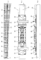
- Figure 3 is a vertical cross section through the railway track and a side view of the box girder which houses the mechanisms of the switch machine.
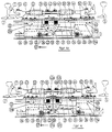
- Figure 4b show the locking function with two locking modules in a view across the switch machine.
- Figure 4a shows a side view of a locking module in a non-trailable version in the longitudinal direction of the switch machine.
- Figure 4c shows a side view of the locking module in a trailable version in the longitudinal direction of the switch machine.
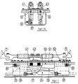
- Figure 5 illustrates the locking module with detecting detectors indicated therein.
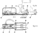
- Figure 6a and Figure 6b show the location of a detector means for detecting the actual position of the switch blade, partly in a vertical section through such a detector means, partly in a plan view.
- Figure 7a and Figure 7b are a side view and a plan view, respectively, from above of the equipment in the switch machine housed in its box girder.
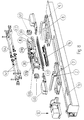
- Figure 8 is a perspective view of units for the switch machine according to the invention.
- Switch machines 9a - 9c are located along the switch in a necessary number. In switches included in a track which is trafficked by high-speed trains, the length of the switch may be considerable, whereby, as shown in the example in Figure 1, six switch machines may be required. At the very branch point 6 in the switch, there extend to the left in the figure switch blades forming rails 7 and 8. These rails 7, 8 are interconnected at the respective switching point (the position of the switch machine 9a-9c) and can be shifted to different end positions constituting the first and second position, respectively, of the switch blade at the switching point.
- One of the switch machines according to Figure 1 consists of a blade point-type switch machine 9a, which serves as a master unit, whereas the other switch machines along the switch blade serve as slave switch machines 9b.
- a movable frog-type switch machine 9c is located at the movable frog.
- the switch machine is shown in its entirety in a view from above in Figure 2 and in a longitudinal view from the side in Figure 3.
- a lid 11 over the motor operating unit is shown to the right in Figures 2 and 3.
- FIG. 7 shows a vertical section along the box girder 10 and a partially sectioned plan view which illustrates, from the righthand end of the box girder 10, the motor operating unit 12, a transmission shaft 13, a ball screw 14 (which constitutes a linear operating unit), and a linear ball bearing 15 in the centre line at the bottom of the box girder 10.
- the motor of the operating unit 12 rotates in a clockwise or counterclockwise direction depending on which control has been given.
- a motor pinion 16 drives a gear ring on the slipping (or friction) clutch 18 which, in turn, drives the transmission shaft 13.
- the transmission shaft 13 transmits the rotation via an elastic coupling 19 to a ball screw 14, which causes a ball nut 21 into a linear motion in the longitudinal direction of the switch machine.
- the ball nut 21 is guided in the linear ball bearing 15, which is mounted at the bottom of the box girder 10.
- two carrier pins 22, 23 are mounted, each of which separately transmits the motion of the ball nut 21 to a drive rod 24 associated with each locking module L1, L2.
- These locking modules L1, L2 and their locking function will be described below.
- a switching device is provided which disengages the motor and connects the gear ring of the friction clutch 18 to a hand-operated switch.
- Changeover to manual operation is achieved by pressing down a lever 11a and turning it 90° around its axis.
- a crank for manual operation of the switch machine is connected to a switch pin for manual operation of the transmission shaft 13, the switch pin being disengaged while at the same time the lever 11a assumes the new position.
- the motor and the sensors mounted in the switch machine are electrically connected to an external central unit by way of two separate contacts 25, which are mounted in the end wall of the box girder 10.
- the type of motor in the operating unit 12 can be chosen freely but consists in the embodiment described of a three-phase asynchronous motor.
- the supply of the motor according to the example is controlled from an external control unit at the switch, the control unit receiving continuous information about and evaluating the state of the sensors in the entire switch operating system.
- the individual motors at the respective switch machine are supplied with different voltages by frequency converter equipment which can control the motor to a speed of rotation adapted to the stroke of the respective switch machine.
- the drive rod 24 in a locking module L2 is influenced by the carrier pin 22.
- the drive bar 24 is brought along in the same movement.
- the operation is started by moving the drive bar 24 about 50 mm to the right.
- the position of the switch blades 7, 8 is secured in the first position by a lefthand lock catch 30 resting on the upper sliding surface 31 of the drive bar 24 and securing the lock catch 30 in a raised position in a first locking slot 32 at the end of a first locking bolt 33b arranged in a first locking block 33, the lefthand lock catch 30 thus preventing the associated switch operating parts from being displaced to the right in the figure, where the switch blades 7, 8 cannot be moved to the right.
- the drive bar 24 at time t 2 permits the lefthand lock catch 30 to fall down into the left-hand unlocking slot 34 of the drive bar 24, unlocking from the first position of the switch has taken place.
- the drive bar 24 Upon continued movement to the right in the figure, the drive bar 24 will, with the righthand lock catch 35 as carrier, via its shaft journal 36, move the lower centre block 37 to the right.
- the righthand lock catch 35 cannot be lifted from the righthand unlocking slot 38, since the uppermost surface of the lock catch slides under the lower sliding surface 39a of a second bolt 39b, arranged in a second locking block 39.
- the upper centre block 42 Via a spring package 41, the upper centre block 42 is urged to accompany the lower centre block 37 in its movement to the right.
- the switch blade connection rods 43, 44 are influenced by the connections thereof to the upper centre block 42, which connections are rotatable around the pins 45, 46.
- connection rods 43, 44 move the switch blades 7, 8 to their new end positions, that is, the second switch position for the respective switch blade.
- the switch blades 7, 8 at time t 3 have reached these second positions, the righthand lock catch 35 has at the same time arrived at a second locking slot 40 in the second bolt 39b, whereby the righthand lock catch 35 has been displaced up in this second locking slot and starts sliding on the upper sliding surface 31 of the drive bar 24.
- the locking is secured according to the above by the drive bar 24 continuing its movement about 50 mm to the right in the figure after time t 3 .
- Figure 4a shows the locking mechanism in the longitudinal direction of the box girder 10
- Figure 4b illustrates in a cross-sectional view two locking modules L1 and L2 operating independently of, and parallel to, each other.
- one of the locking modules By allowing one of the locking modules to act somewhat later than the other, one actively-operating and one passively-operating locking mechanism are obtained.
- the description also shows that the locking mechanisms function independently of the operating mechanism, which means that external forces, which for some reason influence a switch blade 7, 8 in the switch machine, are conveyed to the locking mechanism and hence not supplied to the operating mechanism.
- the locking modules (L1 L2) are designed in a non-trailable version (Fig. 4a), in which a lower centre block (37) via an upper centre block (42) which transmits operation forces to switch blade connection rods (43, 44) are each designed in one piece and hence influence both switch blades (7, 8) simultaneously, as well as a trailable version (Fig. 4c) in which both the lower centre block and the upper centre block are designed in two halves, lower centre block halves (37a, 37b) and upper centre block halves (42a, 42b), whereby in the latter version the switch blade connection rods (43, 44) are influenced by the centre block half (37a, 37b) and the centre block half (42a, 42b) belonging to the respective connection rod (43. 44).
- the adaptation of the stroke of the switch machine is achieved by displaceably mounting the lower centre block 37 and the upper centre block 42 connected thereto along a shaft 50, as shown in Figure 5.
- the shaft 50 in its turn is threaded with its lefthand end by means of a lefthand thread into the first locking block 33, and is threaded with its righthand end by means of a righthand thread into the second locking block 39.
- the first and second locking blocks 33 and 39, respectively, are displaceably screwed to a cover plate 51, secured to the box girder, by means of the screw joint 52.
- the locking blocks 33 and 39, respectively can be moved towards or away from each other, which means that the distance between the above-described two locking positions of the switch machine is changed, since the two locking slots 32, 40 are moved closer to or further away from each other.
- the two lock catches 30,35 transmit the operation movement from the drive 24 to the lower centre block 37 and the other switch operating parts.
- the locking slots 32, 40 also have the function of interrupting this carrier movement. The stroke of the switch machine is thus changed when the locking slots 32 and 40 are moved closer to or further away from each other.
- Rail displacement occurs in the switch, which means that a support rail 2, 5 in the railway track can be displaced in the longitudinal direction in relation to an adjacent switch blade 7, 8, for example due to movements caused by the linear expansion of the rails.
- the switch blade connection rods 43, 44 are rotatably connected to the centre block 42 and to the switch blade 7, 8 (see Figure 2).
- the rotatable connection is designed such that the connection rods are able to turn around pins 45, 46 in the centre block 42 and around pins 54, 54 at the switch blades 7, 8, respectively.
- a space free from obstacles for the connections of the connection rods 43, 44 to the rails of the switch blades permits a relative displacement which in the example amounts to ⁇ 40 mm in the longitudinal direction of the track between the switch blades 7, 8 and the respective support rails 2, 5 thereof, the latter being fixed to the box girder (10).
- Figure 4 shows two inductive sensors 55, 56 which are mounted on the locking blocks 33, 39.
- the drive bar 24 is provided with two recesses 57, 58, which are placed such that their respective position in a locked first and a locked second position open an air gap in front of the respective sensor 55, 56 when the respective sensor is to indicate an adopted locking position.
- the drive bar 24 covers the sensors 55, 56, whereby these indicate metal, that is, locking positions not reached.
- the locking position indication will always assume the correct position for each conceivable setting of the stroke, without necessitating any readjustment whatsoever of the inductive sensors 55, 56 for locking position indication.
- This function is achieved by mounting the sensors 55, 56 at specified locations on the locking blocks 33, 39 and by providing defined positions for the recesses 57, 58 on the drive bar 24.
- the sensors 55, 56 are provided with a self-test function which uninterruptedly tests the ability of the sensor to detect.
- the type of sensor described can, of course, be replaced by other types of sensors, for example mechanical ones.
- the detection function described detects that the lock catches 30 and 35 respectively, independently of the setting of the stroke, are secured in the locking blocks 33 and 39, respectively, by sensing that the determined locking distance (50 mm) of the drive bar 24 has been reached.
- the figures show two detector units 60, 61 which are each mounted on a foot of the respective support rail 2, 5 and over the sleeper box 10, and also show that the detection rod 62 arranged at the detector unit 60, 61 is connected to the switch blade 7, 8 supervised by the detector unit 60, 61.
- the detector unit 60, 61 is connected to the rail foot by means of two hooks 63, which can be tightened with nuts 64.
- the detection rod 62 is connected to the switch blade 7, 8 via a connection piece 65, which in its turn is secured to the switch blade 7, 8 by means of a bolt 66 and a shackle 67.
- the detection rod is provided with a carrier piece 68 which engages in a corresponding recess in the connection piece 65, which means that the connection piece 65 and the carrier piece 68 may slide mutually relative to each other in the longitudinal direction of the track if the support rail 2, 5 and the switch blade 7, 8 are displaced relative to each other due to rail displacement.
- first and second sensors 69 and 70 are equipped with a self-test function as described above and can, of course, be replaced by other types of sensors.
- the detection function described above detects in a direct and secure manner, independently of rail displacement and rail maintenance, the two end positions of the switch blade 7, 8, that is, Pos 1 and Pos 2 according to Figure 6a.
- FIG. 5 An additional detection function of the position and locking of the switch blade 7, 8 is illustrated in Figure 5, in which two inductive sensors 80 and 81, respectively, are shown mounted on the locking blocks 33 and 39, respectively.
- the lefthand lock catch 30 is in locked position against the locking bolt 33b.
- the sensor 80 is placed so as to detect the engagement of the lefthand lock catch 30 with the first locking slot 32 in the first bolt 33b.
- the sensor 81 has been mounted in a position in the second locking block 39 such that the engagement of the righthand lock catch 35 with the second locking slot 40 can be detected.
- the righthand sensor in the figure - sensor 81 - does not detect the presence of the righthand lock catch 35 in locked position.
- the lefthand lock catch 30 in locked position also provides direct information that the switch blade 7, 8 is in its first end position
- this first end position of the switch blade can consequently also be detected by the sensor 80.
- the detection of the assumed first end position of the switch blade 7, 8 by the sensor 80 will thus be interrupted as soon as the lefthand lock catch 35 falls out of its locked position in the first locking slot 32, after the drive bar 24 at time t 2 has moved the whole locking distance of the first lock catch 30.
- the switch blade 7, 8 will assume its second end position.
- the drive bar 24 presses the righthand lock catch 35 up into its locked position in the locking slot 40.
- the sensor 81 detects the presence of the locked righthand lock catch 35 and hence indirectly detects that the second end position of the switch blades 7, 8 is reached.
- the detection function now described thus indirectly detects the position of the switch blade 7, 8 and at the same time that the correlating lock catch 30, 35 is in locked position.
Landscapes
- Engineering & Computer Science (AREA)
- Mechanical Engineering (AREA)
- Railway Tracks (AREA)
- Train Traffic Observation, Control, And Security (AREA)
- Keying Circuit Devices (AREA)
- Electric Propulsion And Braking For Vehicles (AREA)
Claims (14)
- Vorrichtung in einem Eisenbahnschienenstrang zur Betätigung einer Weiche mit einem Betätigungsmechanismus (12) zum Betätigen von Weichenzungen (7, 8) aus einer ersten Endlage in eine zweite Endlage mit einer zur Längsrichtung des Schienenstranges lotrecht gerichteten Bewegung, und ein Blockiermechanismus (L1, L2) zum Blockieren der Lagen der Weichenzungen in deren ersten bzw. zweiten Lagen, wobei der Betätigungsmechanismus und der Blockiermechanismus in einem als eine schienentragende Bohle gestaltetes Kistengestell (10) untergebracht sind, und wobei der Betätigungsmechanismus eine Motorbetätigungseinheit (12) und eine geradlinige Betätigungeinheit (14) umfasst, dadurch gekennzeichnet, dass der Betätigungsmechanismus und der Blockiermechanismus Module umfassen, die zumindestens die genannte Motorbetätigungseinheit (12), die genannte geradlinige Betätigungseinheit (14) und mindestens einen Blockiermodul (L1, L2) beinhalten, wobei jede der genannten Einheiten eine gesonderte Einheit bilden und jede für sich ein Modul bilden, das von der Aussenseite des Kistengestelles zugängig und austauschbar ist.
- Vorrichtung gemäss Patentanspruch 1, dadurch gekennzeichnet, dass der Blockiermechanismus mindestens zwei Blockiermodule (L1, L2) umfasst, die voneinander unabhängig sind, wobei die Blockiermodule je für sich die erste oder die zweite Lage der Weichenzungen (7, 8) blockieren.
- Vorrichtung gemäss Patentanspruch 2, dadurch gekennzeichnet, dass beide Blockiermodule (L1, L2) dieselbe Blockierfolge durchführen, wobei der eine Blockiermodul (L1) aktiv arbeitet, während der andere Blockiermodul (L2) mit gewissem Zeitabstand passiv wirkt.
- Vorrichtung gemäss Patentanspruch 3, dadurch gekennzeichnet, dass der passiv wirkende Blockiermodul (L2) automatisch auf aktives Wirken umschaltet, sollte das erste Blockiermodul (L1) aus irgend einem Grunde betriebsunfähig werden, wodurch die Blockierfunktion die Sicherheitsbedingung erfüllt, dass ein im ersten Blockiermodul (L1) vorliegender Fehler nicht einen gefährlichen Zustand schafft.
- Vorrichtung gemäss Patentanspruch 2, 3 oder 4, dadurch gekennzeichnet, dass die Blockiermodule (L1, L2) in nicht stellbarer Ausführung gestaltet sind, in der ein unterer Mittelblock (37) über einen oberen, die Weichenbetätigungskräfte auf die Weichenverbindungsstangen (43, 44) übertragenden Mittelblock (42) jeweils aus einem Teil besteht und dadurch beide Weichenzungen (7, 8) gleichzeitig beauf - schlagt, und einer verstellbaren Ausführung, in der sowohl der untere Mittelblock und der obere Mittelblock aus zwei Hälften bestehen, den unteren Mittelblockhälften (37a, 37b) bzw. den oberen Mittelblockhälften (42a, 42b), wodurch die Verbindungsstangen (43, 44) in der letztgenannten Ausführung von den den entsprechenden Verbin - dungsstangen (43, 44) zugehörigen unteren Mittelblockhälften (37a, 37b) und oberen Mittelblockhälften (42a, 42b) beaufschlagt werden.
- Vorrichtung gemäss Patentanspruch 1, dadurch gekennzeichnet, dass der Blockiermodulmechanismus für verschiedene Hübe eingestellt werden kann, d.h. für verschiedene Grössen der Längsbewegung der Weichenzunge (7, 8) aus einer ersten in eine zweite Lage.
- Vorrichtung gemäss Patentanspruch 6, dadurch gekennzeichnet, dass die Hubeinstellung durch Verschieben von Blockierblöcken (33, 39) näher oder weiter voneinander in den Blockier-modulen (L1, L2) erfolgt.
- Vorrichtung gemäss Patentanspruch 1, dadurch gekennzeichnet, dass die Verbindungsstangen (43, 44) der Weichenzungen mit den Weichenzungen (7, 8) und mit einem Mittelblock des Betätigungsmechanismus der Verbindungsstangen drehbar verbunden sind, wodurch die Vorrichtung von den Schienenverschiebungen unab - hängig wird.
- Vorrichtung gemäss Patentanspruch 1, dadurch gekennzeichnet, dass die Vorrichtung Ermittlungsteile (60, 61) enthält zum Ermitteln, dass die Weichenzungen (7, 8) ihre erste oder zweite Endlage erreicht haben.
- Vorrichtung gemäss Patentanspruch 1, dadurch gekennzeichnet, dass die Vorrichtung Elemente (55, 56) zum Ermitteln dafür enthält, dass eine Antriebsstange (24) im Betätigungsmechanismus ihre bestimmte Aufgabe und Blockierabstand voll - zogen hat, welches unabhängig von dem Hub an den Weichenzungen (7, 8) geschieht, der in der Vorrichtung eingestellt wurde.
- Vorrichtung gemäss Patentanspruch 1, dadurch gekennzeichnet, dass die Vorrichtung Elemente (80, 81) zum Ermitteln dafür enthält, dass ein Blockierhaken (30, 35) im Blockiermechanismus sich wirklich im Eingriff in einem Blockierschlitz (32, 40) befindet, womit indirekt angezeigt wird, dass die Weichenzunge (7, 8) in einer ersten oder einer zweiten Lage blockiert ist.
- Vorrichtung gemäss Patentanspruch 5, dadurch gekennzeichnet, dass ein Federpaket (41) zwischen den Mittelblöcken (37, 42) installiert ist um die Weichen - zunge (7, 8) mit Federkraft an ihre Anschlagschiene (2, 5) zu drücken, falls die Weichenzunge mit einer Anschlagschiene (2, 5) in Kontakt kommt.
- Vorrichtung gemäss Patentanspruch 1, dadurch gekennzeichnet, dass die Vorrichtung Elemente (80, 81) zur Anzeige dafür enthält, dass die erste oder die zweite Lage der Weichenzungen (7, 8) erreicht worden ist, die eine Ermittlungsfunktion in Gestalt von austauschbare Modulen bildende Ermittlungsteilen (60, 61) umfasst.
- Vorrichtung gemäss Patentanspruch 1, dadurch gekennzeichnet, dass die Motorbetätigungseinheit (12) im Betätigungsmechanismus einen Motor umfasst, der elektrisch, hydraulich oder von Hand angetrieben wird.
Applications Claiming Priority (3)
| Application Number | Priority Date | Filing Date | Title |
|---|---|---|---|
| SE9301801 | 1993-05-27 | ||
| SE9301801A SE506183C2 (sv) | 1993-05-27 | 1993-05-27 | Anordning vid järnvägsspår för omläggning av spårväxel |
| PCT/SE1994/000502 WO1994027853A1 (en) | 1993-05-27 | 1994-05-27 | A device for operating a switch for rail points |
Publications (2)
| Publication Number | Publication Date |
|---|---|
| EP0701517A1 EP0701517A1 (de) | 1996-03-20 |
| EP0701517B1 true EP0701517B1 (de) | 1998-03-25 |
Family
ID=20390062
Family Applications (1)
| Application Number | Title | Priority Date | Filing Date |
|---|---|---|---|
| EP94917859A Revoked EP0701517B1 (de) | 1993-05-27 | 1994-05-27 | Vorrichtung zum betreiben der weichenzungen einer eisenbahnweiche |
Country Status (8)
| Country | Link |
|---|---|
| US (1) | US5620156A (de) |
| EP (1) | EP0701517B1 (de) |
| JP (1) | JPH09504757A (de) |
| AT (1) | ATE164355T1 (de) |
| DE (1) | DE69409232T2 (de) |
| ES (1) | ES2116597T3 (de) |
| SE (1) | SE506183C2 (de) |
| WO (1) | WO1994027853A1 (de) |
Cited By (2)
| Publication number | Priority date | Publication date | Assignee | Title |
|---|---|---|---|---|
| EP1024987B2 (de) † | 1997-10-22 | 2008-02-27 | Alstom Ferroviaria S.P.A. | Schaltkasten für eisenbahn, strassenbahnweichen oder dergleichen |
| DE202010008526U1 (de) | 2010-09-14 | 2010-12-30 | Contec Gmbh Transportation Systems | Betonschwelle |
Families Citing this family (61)
| Publication number | Priority date | Publication date | Assignee | Title |
|---|---|---|---|---|
| ES2124643B1 (es) * | 1995-01-26 | 1999-10-16 | Instalaciones Alfar Sa De | Nueva disposicion del mecanismo de seguridad en desvios, aplicable en traviesas huecas para lineas ferroviarias polivalentes. |
| DE19538966A1 (de) * | 1995-10-19 | 1997-04-24 | Sel Alcatel Ag | Weichenantrieb mit einstellbarem Hub |
| FR2741365B1 (fr) * | 1995-11-22 | 1997-12-26 | Gec Alsthom Transport Sa | Dispositif de verrouillage d'une lame d'aiguille d'un aiguillage, dispositif de manoeuvre et de verrouillage d'une lame d'aiguille, procede de mise en place d'un tel dispositif |
| EP0856608B1 (de) * | 1997-01-31 | 2003-04-09 | Siemens Schweiz AG (Siemens Suisse SA) (Siemens Svizzera SA) Siemens Switzerland Ltd) | Modulare Hohlschwelle |
| DE29709420U1 (de) * | 1997-05-30 | 1998-10-01 | Hanning & Kahl GmbH & Co., 33813 Oerlinghausen | Vorrichtung zum Verriegeln von beweglichen Weichenteilen |
| DE19819162B4 (de) * | 1997-07-17 | 2008-01-10 | Siemens Ag | Schaltung zum Stellen und Überwachen von Weichen mit mehreren Antrieben |
| GB2336615A (en) * | 1998-04-24 | 1999-10-27 | F H Limited | Actuator for a rail switch and crossing system |
| EP1018461A1 (de) * | 1999-01-04 | 2000-07-12 | Siegfried Pütz | Weichenantriebsvorrichtung |
| AU4384699A (en) * | 1999-06-01 | 2000-12-18 | Gabor Horvath | Driving gear for points |
| AU6636000A (en) * | 1999-08-13 | 2001-03-13 | Point Biomedical Corporation | Hollow microspheres with controlled fragility for medical use |
| US6158698A (en) * | 1999-12-09 | 2000-12-12 | Vae Nortrak North America, Inc. | Hollow tie switch assembly |
| ES2184546B2 (es) * | 2000-02-02 | 2003-12-01 | Dimetronic Sa | Dispositivo accionador de agujas ferroviarias para cambio de via. |
| AT4762U1 (de) * | 2000-03-31 | 2001-11-26 | Vae Eisenbahnsysteme Gmbh | Querschwelle für eisenbahngleise |
| AT4844U1 (de) * | 2000-07-14 | 2001-12-27 | Vae Eisenbahnsysteme Gmbh | Einrichtung zur mechanischen und elektrischen überprüfung der verstelleinrichtung von weichenantrieben |
| ATE291543T1 (de) * | 2000-09-21 | 2005-04-15 | Siemens Schweiz Ag | Vorrichtung zur justierung der zungenüberwachung in einem weichenstellsystem |
| DE50009998D1 (de) | 2000-10-05 | 2005-05-12 | Siemens Schweiz Ag Zuerich | Vorrichtung zur Einstellung der Symmetrie in einem Weichenstellsystem |
| ITFI20010028U1 (it) * | 2001-03-27 | 2002-09-27 | Siliani Harmon S P A | Cassa di manovra per scambi |
| AT5706U1 (de) * | 2001-05-07 | 2002-10-25 | Vae Eisenbahnsysteme Gmbh | Verfahren zum einbauen von weichen in geleise sowie weiche zur durchführung dieses verfahrens |
| US6543727B2 (en) * | 2001-08-31 | 2003-04-08 | Vae Nortrak North America Inc. | Assist rod and basket assembly |
| US6648276B1 (en) | 2002-04-30 | 2003-11-18 | Union Switch & Signal, Inc. | Drop down lug for railroad switch application |
| ITSV20030006A1 (it) * | 2003-02-18 | 2004-08-19 | Alstom Transp Spa | Cassa di manovra per deviatori ferroviari tramviari o simili. |
| DE10321604A1 (de) * | 2003-05-13 | 2004-12-02 | SCHWIHAG GESELLSCHAFT FüR EISENBAHNOBERBAU MBH | Kastenschwelle |
| EP1488979A1 (de) * | 2003-06-17 | 2004-12-22 | Siemens Schweiz AG | Verschlussvorrichtung für Weichenzungen mit Profilanpassung |
| US7168662B1 (en) * | 2003-07-07 | 2007-01-30 | Union Switch & Signal, Inc. | Hollow tie railroad switching assembly |
| RU2235030C1 (ru) * | 2003-11-03 | 2004-08-27 | Фадеев Валерий Сергеевич | Стрелочный электропривод |
| US20050178929A1 (en) * | 2004-02-17 | 2005-08-18 | General Electric Company | Switch machine with improved switch point connectors |
| FR2870814B1 (fr) * | 2004-05-28 | 2010-02-19 | Vossloh Cogifer | Dispositif de manoeuvre et de controle d'un aiguillage de voies de chemin de fer |
| FR2878488B1 (fr) * | 2004-12-01 | 2007-03-02 | Vossloh Cogifer Sa | Dispositif de changement de trajectoire pour vehicules sur roues a pneumatiques |
| CA2622413C (en) * | 2005-09-13 | 2016-07-12 | Railway Equipment Company, Inc. | Railway track switch |
| US20080093508A1 (en) * | 2006-10-24 | 2008-04-24 | Union Switch & Signal, Inc. | Unitary body hollow tie for a switch machine |
| US20080093507A1 (en) * | 2006-10-24 | 2008-04-24 | Union Switch & Signal, Inc. | Concrete tie |
| US20080179468A1 (en) * | 2007-01-25 | 2008-07-31 | Lewis Hemphill | Model railroad track switch actuator assembly |
| US20080251649A1 (en) * | 2007-04-10 | 2008-10-16 | Justin Salmans | Railway Switching System |
| US7699272B2 (en) | 2007-09-14 | 2010-04-20 | Jim Arnold | Railroad switching indicator mechanism |
| US8215591B2 (en) * | 2007-10-10 | 2012-07-10 | The Texas A&M University System | Guideway switching mechanism |
| AT507216B1 (de) * | 2008-09-11 | 2010-03-15 | Vae Eisenbahnsysteme Gmbh | Vorrichtung zum festlegen einer weichenstelleinrichtung an backenschienen einer schienenweiche |
| RU2408488C2 (ru) * | 2009-01-23 | 2011-01-10 | Общество с ограниченной ответственностью "НТЦ Информационные Технологии" | Способ контроля соединения остряка с шибером, прилегания остряка к рамному рельсу и устройство для его осуществления |
| RU2395637C1 (ru) * | 2009-06-05 | 2010-07-27 | Общество с ограниченной ответственностью "Научно-Технический Центр Информационные Технологии" | Стрелочный перевод |
| US7946538B1 (en) * | 2009-12-09 | 2011-05-24 | Donald Coy Beaman | External point spring locking device |
| EP2402505B1 (de) * | 2010-07-02 | 2014-12-17 | Jez Sistemas Ferroviarios, S.l. | Betätigungs- und Verschlussvorrichtung für eine Schienenschaltvorrichtung |
| EP2565099B1 (de) * | 2011-08-30 | 2017-11-29 | ALSTOM Transport Technologies | Stellvorrichtung für eine Eisenbahnweiche |
| US8985526B2 (en) * | 2012-04-05 | 2015-03-24 | Ansaldo Sts Usa, Inc. | Swivel point connector for railroad switches |
| US20130264431A1 (en) * | 2012-04-05 | 2013-10-10 | Daniel H. Brushwood | Rail mount point detector for railroad switches |
| FR2989049B1 (fr) * | 2012-04-10 | 2015-10-02 | Pascal Teyssier | Mecanisme de manoeuvre d'aiguillage |
| RU2544441C2 (ru) * | 2012-06-14 | 2015-03-20 | Открытое Акционерное Общество "Российские Железные Дороги" | Стрелочный электропривод |
| ITFI20120182A1 (it) * | 2012-09-14 | 2014-03-15 | Wegh Group S P A | "assieme di attacco per operare controllo e movimentazione degli aghi di un deviatoio" |
| FR3003531B1 (fr) * | 2013-03-19 | 2017-01-13 | Pascal Teyssier | Mecanisme de manoeuvre d'aiguillage |
| JP6309716B2 (ja) * | 2013-07-05 | 2018-04-11 | 東海旅客鉄道株式会社 | トングレールの開口量検出装置 |
| RU2570845C2 (ru) * | 2014-01-31 | 2015-12-10 | Открытое акционерное общество "Объединенные электротехнические заводы" (ОАО "ЭЛТЕЗА") | Привод стрелочный горочный пневматический (варианты) |
| EP2923914B1 (de) | 2014-03-25 | 2016-12-14 | Siemens Schweiz AG | Hohlschwellenweichenstellsystem mit Nockenstangenhubbegrenzung |
| PL3439939T3 (pl) * | 2016-03-07 | 2021-07-19 | Wolber Antriebstechnik Gmbh | Urządzenie blokujące na dwóch, ruchomych względem siebie ślizgowo po prowadnicy elementach |
| US10953897B2 (en) * | 2016-09-30 | 2021-03-23 | Hitachi Rail Sts Usa, Inc. | Electronic circuit controller for railway switch machine, railway switch machine and railway switching system including same |
| CZ30652U1 (cs) * | 2017-04-06 | 2017-05-09 | DT-výhybkárna a strojírna a.s., | Výměnový závěr |
| RU193535U1 (ru) * | 2019-07-09 | 2019-10-31 | Общество с ограниченной ответственностью "Термотрон-Завод" | Стрелочный электропривод |
| RU193014U1 (ru) * | 2019-08-14 | 2019-10-10 | Общество С Ограниченной Ответственностью "Инновационные Технологии На Железнодорожном Транспорте" (Ооо "Итжт") | Электропривод стрелочный |
| RU194948U1 (ru) * | 2019-11-15 | 2020-01-09 | Открытое акционерное общество "Объединенные электротехнические заводы" | Горочный стрелочный электропривод |
| EP3835168A1 (de) | 2019-12-11 | 2021-06-16 | ALSTOM Transport Technologies | Eisenbahnweichenmaschine mit einstellbarem hub |
| CA3201365A1 (en) * | 2020-12-09 | 2022-06-16 | Andrew Imhof | Independent rail test release mechanism |
| CN112550355B (zh) * | 2020-12-20 | 2023-01-10 | 通号万全信号设备有限公司 | 一种转辙机用行程可调接点座 |
| CN113353121B (zh) * | 2021-06-23 | 2023-04-11 | 浙江树人学院(浙江树人大学) | 一种交通轨道变道装置及其使用方法 |
| WO2023059314A1 (en) * | 2021-10-04 | 2023-04-13 | BEAMAN, Mona | Railroad switch device for moving railroad switch points |
Family Cites Families (10)
| Publication number | Priority date | Publication date | Assignee | Title |
|---|---|---|---|---|
| DE614467C (de) * | 1934-01-13 | 1935-06-14 | Scheidt & Bachmann Eisenbahnsi | Sicherung von Weichen durch Handverschluss |
| DE1755105C3 (de) * | 1968-03-29 | 1975-03-13 | Bielefelder Elektrotechnische Fabrik Hanning & Kahl, 4800 Bielefeld | Zungenprüfer für eine Vorrichtung zum Umstellen von Rillenschienenweichen |
| SE396425B (sv) * | 1976-01-19 | 1977-09-19 | Elektromekano Bredaryd | Sparvexel |
| DE3543403A1 (de) * | 1985-12-07 | 1987-06-11 | Laeis Gmbh | Vorrichtung zum verriegeln von schienenspitzen, insbesondere von weichenzungen mit den zugehoerigen backenschienen |
| AT388198B (de) * | 1987-06-09 | 1989-05-10 | Voest Alpine Ag | Weichenbetaetigungsvorrichtung |
| FR2623461B1 (fr) * | 1987-11-23 | 1990-03-02 | Alsthom | Dispositif de motorisation d'un aiguillage |
| IT1213950B (it) * | 1987-12-16 | 1990-01-05 | Sasib Spa | Dispositivo universale di fermascambiatura esterna per deviatoi ferroviari |
| US5192038A (en) * | 1989-09-11 | 1993-03-09 | Ocampo Salvador C | Safety detector for railroad switch points with visual indicator mechanism |
| DK0467865T3 (da) * | 1990-07-19 | 1994-10-31 | Siliani Angiolo Spa | Apparat til betjening af skiftetunger i jernbanesporskifter |
| IT1242226B (it) * | 1990-10-10 | 1994-03-03 | Sasib Spa | Dispositivo di manovra per deviatoi ferroviari, in particolare per linee ad alta velocita' |
-
1993
- 1993-05-27 SE SE9301801A patent/SE506183C2/sv not_active IP Right Cessation
-
1994
- 1994-05-27 US US08/549,756 patent/US5620156A/en not_active Expired - Fee Related
- 1994-05-27 WO PCT/SE1994/000502 patent/WO1994027853A1/en not_active Ceased
- 1994-05-27 AT AT94917859T patent/ATE164355T1/de not_active IP Right Cessation
- 1994-05-27 DE DE69409232T patent/DE69409232T2/de not_active Expired - Fee Related
- 1994-05-27 ES ES94917859T patent/ES2116597T3/es not_active Expired - Lifetime
- 1994-05-27 JP JP7500547A patent/JPH09504757A/ja active Pending
- 1994-05-27 EP EP94917859A patent/EP0701517B1/de not_active Revoked
Cited By (2)
| Publication number | Priority date | Publication date | Assignee | Title |
|---|---|---|---|---|
| EP1024987B2 (de) † | 1997-10-22 | 2008-02-27 | Alstom Ferroviaria S.P.A. | Schaltkasten für eisenbahn, strassenbahnweichen oder dergleichen |
| DE202010008526U1 (de) | 2010-09-14 | 2010-12-30 | Contec Gmbh Transportation Systems | Betonschwelle |
Also Published As
| Publication number | Publication date |
|---|---|
| SE506183C2 (sv) | 1997-11-17 |
| DE69409232D1 (de) | 1998-04-30 |
| JPH09504757A (ja) | 1997-05-13 |
| SE9301801D0 (sv) | 1993-05-27 |
| ES2116597T3 (es) | 1998-07-16 |
| WO1994027853A1 (en) | 1994-12-08 |
| SE9301801L (sv) | 1994-11-28 |
| EP0701517A1 (de) | 1996-03-20 |
| ATE164355T1 (de) | 1998-04-15 |
| DE69409232T2 (de) | 1998-11-12 |
| US5620156A (en) | 1997-04-15 |
Similar Documents
| Publication | Publication Date | Title |
|---|---|---|
| EP0701517B1 (de) | Vorrichtung zum betreiben der weichenzungen einer eisenbahnweiche | |
| AU2004213172B8 (en) | Switch machine for railway and tramway switches or the like | |
| US5669587A (en) | Point detection and indication with latch out means | |
| US20040135036A1 (en) | Method for installing points in railway tracks and points for carrying out said method | |
| US12221144B2 (en) | Railroad switch device for moving railroad switch points | |
| EP2535238B1 (de) | Kreuzungsweiche einer Eisenbahn-, Straßenbahn oder dergleichen | |
| AU754903B2 (en) | Captive point detection system with single switch position target | |
| AU2003237561B2 (en) | Point machine for movable frogs | |
| EP1077860B1 (de) | Betätigungsvorrichtung für weichen | |
| US11780478B1 (en) | Railroad switch device | |
| CN118343182A (zh) | 一种脱轨器动作拉杆 | |
| US20230002977A1 (en) | Gapless railway diamond: a new type of railway track component providing unbroken running surfaces across the flangeways of an intersecting railway line | |
| WO2000053848A1 (en) | Pivotable guidebeam switch | |
| RO116022B1 (ro) | Mecanism de manevrare pentru macazul de cale ferata | |
| US5590857A (en) | Trailing device for a railroad switch layout | |
| KR20020018653A (ko) | 가이드웨이 절환스위치 | |
| CA1189180A (en) | Dual control trailable railway switch machine | |
| US2184870A (en) | Ralway switch operating mechanism | |
| GB2313611A (en) | Monitoring railway point electric operating mechanisms | |
| US2387826A (en) | Railway switch operating mechanism | |
| GB2391034A (en) | Railway points assembly | |
| US20130264431A1 (en) | Rail mount point detector for railroad switches | |
| WO2024226051A1 (en) | Railroad switch device | |
| GB2367410A (en) | Railway vehicle monitoring arrangement | |
| EP4222038A1 (de) | Eisenbahnweichenvorrichtung zum bewegen von eisenbahnweichenpunkten |
Legal Events
| Date | Code | Title | Description |
|---|---|---|---|
| PUAI | Public reference made under article 153(3) epc to a published international application that has entered the european phase |
Free format text: ORIGINAL CODE: 0009012 |
|
| 17P | Request for examination filed |
Effective date: 19951219 |
|
| AK | Designated contracting states |
Kind code of ref document: A1 Designated state(s): AT CH DE DK ES FR GB IT LI NL |
|
| GRAG | Despatch of communication of intention to grant |
Free format text: ORIGINAL CODE: EPIDOS AGRA |
|
| 17Q | First examination report despatched |
Effective date: 19970613 |
|
| GRAG | Despatch of communication of intention to grant |
Free format text: ORIGINAL CODE: EPIDOS AGRA |
|
| GRAG | Despatch of communication of intention to grant |
Free format text: ORIGINAL CODE: EPIDOS AGRA |
|
| GRAH | Despatch of communication of intention to grant a patent |
Free format text: ORIGINAL CODE: EPIDOS IGRA |
|
| GRAH | Despatch of communication of intention to grant a patent |
Free format text: ORIGINAL CODE: EPIDOS IGRA |
|
| GRAA | (expected) grant |
Free format text: ORIGINAL CODE: 0009210 |
|
| AK | Designated contracting states |
Kind code of ref document: B1 Designated state(s): AT CH DE DK ES FR GB IT LI NL |
|
| PG25 | Lapsed in a contracting state [announced via postgrant information from national office to epo] |
Ref country code: NL Free format text: LAPSE BECAUSE OF FAILURE TO SUBMIT A TRANSLATION OF THE DESCRIPTION OR TO PAY THE FEE WITHIN THE PRESCRIBED TIME-LIMIT Effective date: 19980325 Ref country code: LI Free format text: LAPSE BECAUSE OF FAILURE TO SUBMIT A TRANSLATION OF THE DESCRIPTION OR TO PAY THE FEE WITHIN THE PRESCRIBED TIME-LIMIT Effective date: 19980325 Ref country code: CH Free format text: LAPSE BECAUSE OF FAILURE TO SUBMIT A TRANSLATION OF THE DESCRIPTION OR TO PAY THE FEE WITHIN THE PRESCRIBED TIME-LIMIT Effective date: 19980325 Ref country code: AT Free format text: LAPSE BECAUSE OF FAILURE TO SUBMIT A TRANSLATION OF THE DESCRIPTION OR TO PAY THE FEE WITHIN THE PRESCRIBED TIME-LIMIT Effective date: 19980325 |
|
| REF | Corresponds to: |
Ref document number: 164355 Country of ref document: AT Date of ref document: 19980415 Kind code of ref document: T |
|
| REG | Reference to a national code |
Ref country code: CH Ref legal event code: EP |
|
| REF | Corresponds to: |
Ref document number: 69409232 Country of ref document: DE Date of ref document: 19980430 |
|
| ET | Fr: translation filed | ||
| PGFP | Annual fee paid to national office [announced via postgrant information from national office to epo] |
Ref country code: DK Payment date: 19980515 Year of fee payment: 5 |
|
| ITF | It: translation for a ep patent filed | ||
| PGFP | Annual fee paid to national office [announced via postgrant information from national office to epo] |
Ref country code: NL Payment date: 19980531 Year of fee payment: 5 |
|
| PGFP | Annual fee paid to national office [announced via postgrant information from national office to epo] |
Ref country code: CH Payment date: 19980611 Year of fee payment: 5 |
|
| PG25 | Lapsed in a contracting state [announced via postgrant information from national office to epo] |
Ref country code: DK Free format text: LAPSE BECAUSE OF FAILURE TO SUBMIT A TRANSLATION OF THE DESCRIPTION OR TO PAY THE FEE WITHIN THE PRESCRIBED TIME-LIMIT Effective date: 19980625 |
|
| REG | Reference to a national code |
Ref country code: ES Ref legal event code: FG2A Ref document number: 2116597 Country of ref document: ES Kind code of ref document: T3 |
|
| NLV1 | Nl: lapsed or annulled due to failure to fulfill the requirements of art. 29p and 29m of the patents act | ||
| REG | Reference to a national code |
Ref country code: CH Ref legal event code: PL |
|
| PLBI | Opposition filed |
Free format text: ORIGINAL CODE: 0009260 |
|
| PLBF | Reply of patent proprietor to notice(s) of opposition |
Free format text: ORIGINAL CODE: EPIDOS OBSO |
|
| 26 | Opposition filed |
Opponent name: SIEMENS SCHWEIZ AG Effective date: 19981224 |
|
| PLBF | Reply of patent proprietor to notice(s) of opposition |
Free format text: ORIGINAL CODE: EPIDOS OBSO |
|
| REG | Reference to a national code |
Ref country code: GB Ref legal event code: 732E |
|
| REG | Reference to a national code |
Ref country code: FR Ref legal event code: TP Ref country code: FR Ref legal event code: CD Ref country code: FR Ref legal event code: CA |
|
| PGFP | Annual fee paid to national office [announced via postgrant information from national office to epo] |
Ref country code: GB Payment date: 20010412 Year of fee payment: 8 |
|
| PGFP | Annual fee paid to national office [announced via postgrant information from national office to epo] |
Ref country code: FR Payment date: 20010507 Year of fee payment: 8 |
|
| PGFP | Annual fee paid to national office [announced via postgrant information from national office to epo] |
Ref country code: DE Payment date: 20010509 Year of fee payment: 8 |
|
| PGFP | Annual fee paid to national office [announced via postgrant information from national office to epo] |
Ref country code: ES Payment date: 20010514 Year of fee payment: 8 |
|
| RDAH | Patent revoked |
Free format text: ORIGINAL CODE: EPIDOS REVO |
|
| RDAG | Patent revoked |
Free format text: ORIGINAL CODE: 0009271 |
|
| STAA | Information on the status of an ep patent application or granted ep patent |
Free format text: STATUS: PATENT REVOKED |
|
| 27W | Patent revoked |
Effective date: 20001108 |
|
| GBPR | Gb: patent revoked under art. 102 of the ep convention designating the uk as contracting state |
Free format text: 20001108 |