EP0700815B1 - Elektronisch regelbarer Bremskraftverstärker mit einer Leitungsdurchführung - Google Patents
Elektronisch regelbarer Bremskraftverstärker mit einer Leitungsdurchführung Download PDFInfo
- Publication number
- EP0700815B1 EP0700815B1 EP95112940A EP95112940A EP0700815B1 EP 0700815 B1 EP0700815 B1 EP 0700815B1 EP 95112940 A EP95112940 A EP 95112940A EP 95112940 A EP95112940 A EP 95112940A EP 0700815 B1 EP0700815 B1 EP 0700815B1
- Authority
- EP
- European Patent Office
- Prior art keywords
- brake booster
- booster according
- seal
- movable wall
- feed
- Prior art date
- Legal status (The legal status is an assumption and is not a legal conclusion. Google has not performed a legal analysis and makes no representation as to the accuracy of the status listed.)
- Expired - Lifetime
Links
- 239000011324 bead Substances 0.000 claims description 9
- 239000000463 material Substances 0.000 claims description 7
- 238000005192 partition Methods 0.000 claims description 7
- 238000005096 rolling process Methods 0.000 claims description 5
- 238000007789 sealing Methods 0.000 claims description 4
- 238000002788 crimping Methods 0.000 claims description 2
- 238000005476 soldering Methods 0.000 claims description 2
- 230000000149 penetrating effect Effects 0.000 claims 9
- 239000012528 membrane Substances 0.000 description 15
- 238000009434 installation Methods 0.000 description 3
- 230000008878 coupling Effects 0.000 description 1
- 238000010168 coupling process Methods 0.000 description 1
- 238000005859 coupling reaction Methods 0.000 description 1
- 230000000694 effects Effects 0.000 description 1
- 230000005611 electricity Effects 0.000 description 1
- 239000000835 fiber Substances 0.000 description 1
- 239000003365 glass fiber Substances 0.000 description 1
- 238000004519 manufacturing process Methods 0.000 description 1
- 239000002184 metal Substances 0.000 description 1
- 230000035515 penetration Effects 0.000 description 1
- 230000002093 peripheral effect Effects 0.000 description 1
- 230000008054 signal transmission Effects 0.000 description 1
- 229920003002 synthetic resin Polymers 0.000 description 1
- 239000000057 synthetic resin Substances 0.000 description 1
Images


Classifications
-
- H—ELECTRICITY
- H01—ELECTRIC ELEMENTS
- H01R—ELECTRICALLY-CONDUCTIVE CONNECTIONS; STRUCTURAL ASSOCIATIONS OF A PLURALITY OF MUTUALLY-INSULATED ELECTRICAL CONNECTING ELEMENTS; COUPLING DEVICES; CURRENT COLLECTORS
- H01R13/00—Details of coupling devices of the kinds covered by groups H01R12/70 or H01R24/00 - H01R33/00
- H01R13/73—Means for mounting coupling parts to apparatus or structures, e.g. to a wall
- H01R13/74—Means for mounting coupling parts in openings of a panel
-
- B—PERFORMING OPERATIONS; TRANSPORTING
- B60—VEHICLES IN GENERAL
- B60T—VEHICLE BRAKE CONTROL SYSTEMS OR PARTS THEREOF; BRAKE CONTROL SYSTEMS OR PARTS THEREOF, IN GENERAL; ARRANGEMENT OF BRAKING ELEMENTS ON VEHICLES IN GENERAL; PORTABLE DEVICES FOR PREVENTING UNWANTED MOVEMENT OF VEHICLES; VEHICLE MODIFICATIONS TO FACILITATE COOLING OF BRAKES
- B60T13/00—Transmitting braking action from initiating means to ultimate brake actuator with power assistance or drive; Brake systems incorporating such transmitting means, e.g. air-pressure brake systems
- B60T13/10—Transmitting braking action from initiating means to ultimate brake actuator with power assistance or drive; Brake systems incorporating such transmitting means, e.g. air-pressure brake systems with fluid assistance, drive, or release
- B60T13/24—Transmitting braking action from initiating means to ultimate brake actuator with power assistance or drive; Brake systems incorporating such transmitting means, e.g. air-pressure brake systems with fluid assistance, drive, or release the fluid being gaseous
- B60T13/46—Vacuum systems
-
- B—PERFORMING OPERATIONS; TRANSPORTING
- B60—VEHICLES IN GENERAL
- B60T—VEHICLE BRAKE CONTROL SYSTEMS OR PARTS THEREOF; BRAKE CONTROL SYSTEMS OR PARTS THEREOF, IN GENERAL; ARRANGEMENT OF BRAKING ELEMENTS ON VEHICLES IN GENERAL; PORTABLE DEVICES FOR PREVENTING UNWANTED MOVEMENT OF VEHICLES; VEHICLE MODIFICATIONS TO FACILITATE COOLING OF BRAKES
- B60T13/00—Transmitting braking action from initiating means to ultimate brake actuator with power assistance or drive; Brake systems incorporating such transmitting means, e.g. air-pressure brake systems
- B60T13/10—Transmitting braking action from initiating means to ultimate brake actuator with power assistance or drive; Brake systems incorporating such transmitting means, e.g. air-pressure brake systems with fluid assistance, drive, or release
- B60T13/24—Transmitting braking action from initiating means to ultimate brake actuator with power assistance or drive; Brake systems incorporating such transmitting means, e.g. air-pressure brake systems with fluid assistance, drive, or release the fluid being gaseous
- B60T13/46—Vacuum systems
- B60T13/52—Vacuum systems indirect, i.e. vacuum booster units
- B60T13/569—Vacuum systems indirect, i.e. vacuum booster units characterised by piston details, e.g. construction, mounting of diaphragm
-
- B—PERFORMING OPERATIONS; TRANSPORTING
- B60—VEHICLES IN GENERAL
- B60T—VEHICLE BRAKE CONTROL SYSTEMS OR PARTS THEREOF; BRAKE CONTROL SYSTEMS OR PARTS THEREOF, IN GENERAL; ARRANGEMENT OF BRAKING ELEMENTS ON VEHICLES IN GENERAL; PORTABLE DEVICES FOR PREVENTING UNWANTED MOVEMENT OF VEHICLES; VEHICLE MODIFICATIONS TO FACILITATE COOLING OF BRAKES
- B60T13/00—Transmitting braking action from initiating means to ultimate brake actuator with power assistance or drive; Brake systems incorporating such transmitting means, e.g. air-pressure brake systems
- B60T13/10—Transmitting braking action from initiating means to ultimate brake actuator with power assistance or drive; Brake systems incorporating such transmitting means, e.g. air-pressure brake systems with fluid assistance, drive, or release
- B60T13/66—Electrical control in fluid-pressure brake systems
- B60T13/72—Electrical control in fluid-pressure brake systems in vacuum systems or vacuum booster units
Definitions
- the present invention relates to an electronically controllable Brake booster with an implementation with the features of the preamble of claim 1 as it from the US 4,944,214 is known.
- the existing in the electronically controllable brake booster Actuators are installed in the engine compartment of the Electronic control unit arranged in the vehicle with electricity or Control signals supplied and in the brake booster Arranged sensors deliver signals to the electronic Control unit for further processing.
- EP-A-0 331 084 describes an electrical connector which a fluid-tight passage of electrical signals through a Partition, in particular a plate of a gear or other mechanical vehicle components.
- the plug has a cylindrical block that passes through the partition and through a peripheral plug flange on one of its sides is withheld. On the other side of the partition is with the block coupled by a bayonet lock. Through the block are wires and contact pins carried out.
- a groove in which an O-ring seal is arranged is in the cylindrical outer surface of the block formed a groove in which an O-ring seal is arranged is.
- Such an O-ring seal is indeed fluid-tight, However, it is not sufficient to be gas-tight, especially when higher pressures, as required for brake boosters is to seal.
- the present invention is therefore based on the problem an electrical line through the movable wall between the two pneumatic working chambers of the brake booster to carry out, easy installation and high reliability the arrangement in operation can be guaranteed should.
- This arrangement has the unexpected effect that despite the axial movement of the wall between the two working chambers a hermetic penetration of the line from one Working chamber in the next is possible, while building the Pressure difference between the two pneumatic working chambers no (time) losses due to flowing through next to the cable duct Air occur.
- the seal with one connected to a part of the movable wall Roll membrane made in one piece.
- the seal preferably has a web with one opposite the rest of the roller membrane, the greater the thickness of the material through the movable wall protruding section of the cable bushing to keep in a defined position, so that even with movements of the movable wall through the cable duct outgoing cables no significant side Tractive forces can be caused, which cause slipping the cable duct in the seal and thereby causing a leak in the overall arrangement could.
- the seal preferably has at least one holder partially surrounding bead to ensure the stable reception of the cable entry to improve even further.
- the bead forms a step with the web, in which the holder is at least partially received.
- the cable entry in the seal preferably taken up against rotation. This can be achieved, for example, in that the bead and / or the web have a recess into which a correspondingly shaped Part of the cable entry engages.
- the cable duct can be installed relatively easily in the seal.
- the one surrounding the section protruding through the movable wall Area of the seal has at least one sealing lip. This can safely enclose the cable duct and thus hermetically separate the two working chambers.
- the fastener and the movable one Section protruding through the wall at least one each Recess or at least one in the respective recess engaging lead.
- the recess and the projection can then be designed to be latched together.
- the cable bushing has at least one connector pin on, both ends of which are arranged in the line bushing Protrude partition. Preferably at least one End of the connector pins opposite one end of the through the movable wall protruding section or the bracket set back. The ends of the pin are one Connection cable electrically connected. If the line as Glass fiber line is configured, a corresponding one can also be used here Line coupling may be provided.
- the connector pin (if necessary together with the electrically connected one Connection cable) is preferably hermetic surrounding hardening metal.
- the electrical connection from the first working chamber to the second working chamber between one end of the connector pin and the connecting cable can be soldered, crimped, squeezed or be produced by a plug connection.
- Fig. 1 is a part of an electronically controllable brake booster shown the first pneumatic working chamber 11 and a second pneumatic working chamber 12, separated from each other by a movable wall 13 are.
- the movable wall has a rigid part 14 in shape of a circular force-transmitting membrane plate on the with a rolling membrane made of a rubber-like material 16 is connected.
- the roller membrane 16 projects above the membrane plate along its circumference in the radial direction and is with a housing shell 17 only partially illustrated hermetically connected.
- a control housing 18 a - not further illustrated - control valve arrangement connected.
- the Membrane plate 14 In the radial direction close to the control housing 18, the Membrane plate 14 has a circular opening 19 with a Opening 21 is aligned with substantially the same diameter.
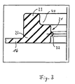
- the rolling membrane 16 is in the area surrounding the opening 21 provided with a web 22, one compared to the rest Roll membrane 16 has approximately doubled material thickness, whereby a seal 22 is formed.
- On the membrane plate 14 facing away Side of the seal has a bead 23, the one with respect to the opening 21 enlarged inside diameter has, so that the web 22 together with the bead 23 a step 24 forms.
- a line bushing generally designated 26 has one substantially cylindrical cross-sectional shape and has one through the movable wall 14 in the region of the opening 19 and through the web 22 of the seal in the region of the opening 21 projecting section 27, the free end 28 in the second pneumatic working chamber 12 protrudes.
- the line bushing 26 has the end of the section 27 a bracket 29, which is integrally formed on the section 27 is, and compared to this an enlarged diameter has, which is dimensioned so that the bracket 29 in the step 24 is included.
- the bead 23 has a radial recess on, in which a molded on the holder radial Extension 31 engages positively (see Fig. 2).
- the cable bushing 26 is movable with its Section 14 projecting through wall 14 in the region of the opening 21, which surrounds the section 27, received in sliding fit.
- the line bushing 26 points into the second pneumatic one Working chamber 12 projecting end 28 a fastener in the form of a cap 33 with a substantially in longitudinal section U-shaped profile on.
- a fastener in the form of a cap 33 with a substantially in longitudinal section U-shaped profile on.
- On the inside of the cylindrical Cap 33 is a circumferential acting as a rest Projection 34 which in one on the outside of the cylindrical Section 27 engages formed recess 35.
- the projection 34 is with an inclined ramp 36 provided and one perpendicular to the inner wall Edge 37.
- the free end 28 of section 27 of the Cable bushing 26 is chamfered on the outside, so that the cap 35 over the section 27 against the membrane plate 14 can be pushed so that the recess 35 and the Can lock projection 34 together.
- the dimensions the recess 35 and the projection 34 and the Cap 33 and the longitudinal extent of the section 27 opposite the bracket 29 and the material thickness of the web 22 dimensioned so that in one embodiment, the line bushing 26 with little axial play - through the cap 33 and the bracket 29 limited - is received in the opening 19 or 21, while in a second embodiment of the fastener 33 presses the seal 22 against the holder 29.
- the line bushing 26 has in the embodiment shown (see Fig. 2) three pins 40a, 40b, 40c, whose both ends 42, 43 each in the line bushing arranged partition 45 protrude.
- the connector pins 40a, 40b, 40c are arranged hermetically in the partition and at the end 42 of the connecting pins located in the holder 29 40a, 40b, 40c, these are opposite the end face of the Bracket 29 set back. At the opposite end the ends 43 of the connecting pins 40a, 40b, 40c practically extend up to the end face of the end 28 of the section 27.
- each pin 40a, 40b, 40c with one wire of a cable A, B by soldering, Crimping, squeezing or a plug connection connected so that an electrical connection from the first working chamber to the second working chamber made by the cable entry is.
- connection cable A, B with the ends of the pins 40a, 40b, 40c is surrounded by a hermetically hardening (synthetic resin) material, which further improves the seal.
- a major advantage of the invention is that the Seal part of the movable wall, especially part the roller membrane can be. That means that through the special Design of the roll membrane in the area of the cable duct several functions are integrated with each other. This allows a particularly simple and inexpensive installation.
Landscapes
- Engineering & Computer Science (AREA)
- Transportation (AREA)
- Mechanical Engineering (AREA)
- Braking Systems And Boosters (AREA)
- Surgical Instruments (AREA)
Description
- Fig. 1
- einen Längsschnitt eines Bremskraftverstärkers in einer Teilansicht zeigt;
- Fig. 2
- eine Draufsicht auf eine in Fig. 1 dargestellte bewegliche Wand in einem kleineren Maßstab zeigt; und
- Fig. 3
- eine in einer mit der beweglichen Wand verbundenen Rollmembran ausgebildete Dichtung in einer vergrößerten Schnittdarstellung zeigt.
Claims (19)
- Elektronisch regelbarer Bremskraftverstärker mit einer Durchführung, dereine erste pneumatische Arbeitskammer (11),eine zweite pneumatische Arbeitskammer (12), die voneinander durch eine bewegliche Wand (13) getrennt sind,eine die bewegliche Wand (13) durchdringende Durchführung (26) miteinem durch die bewegliche Wand (13) hindurchragenden Abschnitt (27) undeiner Halterung (29), die die Beweglichkeit der Durchführung (26) zumindest in deren Längsrichtung begrenzt, undeine die Durchführung (26) im Bereich der beweglichen Wand (13) umgebende Dichtung (22) aufweist, wobeidie Dichtung (22) den durch die bewegliche Wand hindurchragenden Abschnitt (27) der Durchführung (26) fest umgreift und/oder die Dichtung (22) an der Halterung (29) anliegt, dadurch gekennzeichnet, daßdie Durchführung eine Leitungsdurchführung (26) für wenigstens eine elektrische Leitung (A, B) ist.
- Bremskraftverstärker nach Anspruch 1, bei dem die Dichtung (22) mit einer mit einem starren Teil (14) der beweglichen Wand (13) verbundenen Rollmembran (16) einstückig ausgebildet ist.
- Bremskraftverstärker nach Anspruch 2, bei dem die Dichtung (22) einen Steg mit einer gegenüber der übrigen Rollmembran (16) größeren Materialdicke aufweist.
- Bremskraftverstärker nach einem der Ansprüche 1 bis 3, bei dem die Dichtung (22) einen die Halterung (29) zumindest teilweise umgebenden Wulst (23) aufweist.
- Bremskraftverstärker nach Anspruch 4, bei dem der Wulst (23) mit dem Steg (22) eine Stufe (24) bildet, in der die Halterung (29) zumindest teilweise aufgenommen ist.
- Bremskraftverstärker nach einem der Ansprüche 2 bis 5, bei dem die Leitungsdurchführung (26) in der Dichtung (22) verdrehsicher aufgenommen ist.
- Bremskraftverstärker nach Anspruch 6, soweit dieser auf Anspruch 5 zurückbezogen ist, bei dem der Wulst (23) und/oder der Steg (23) eine Ausnehmung (30) aufweisen, in die ein entsprechend geformter Teil (31) der Leitungsdurchführung (26) eingreift.
- Bremskraftverstärker nach einem der Ansprüche 2 bis 7, bei dem die Dichtung (22) mit ihrem den durch die bewegliche Wand (13) hindurchragenden Abschnitt (27) umgebenden Bereich (21) die Leitungsdurchführung (26) im Schiebesitz umgreift.
- Bremskraftverstärker nach dem vorhergehenden Anspruch, bei dem der den durch die bewegliche Wand (13) hindurchragende Abschnitt (27) umgebende Bereich (21) der Dichtung (22) wenigstens eine Dichtlippe (32) aufweist.
- Bremskraftverstärker nach einem der Ansprüche 2 bis 9, bei dem ein Befestigungselement (33) mit dem durch die bewegliche Wand (13) hindurchragenden Abschnitt (27) in Eingriff bringbar ist, das die Leitungsdurchführung (26) mit der Dichtung (22) unverlierbar verbindet.
- Bremskraftverstärker nach dem vorhergehenden Anspruch, bei dem das Befestigungselement (33) und der durch die bewegliche Wand (13) hindurchragende Abschnitt (27) jeweils wenigstens eine Ausnehmung (35) bzw. wenigstens einen in die jeweilige Ausnehmung (35) eingreifenden Vorsprung (34) aufweisen.
- Bremskraftverstärker nach einem der Ansprüche 10 bis 11, bei dem das Befestigungselement (33) den durch die bewegliche Wand (13) hindurchragenden Abschnitt (27) umgibt und die Ausnehmung (35) bzw. der Vorsprung (34) miteinander verrastbar sind.
- Bremskraftverstärker nach einem der Ansprüche 10 bis 12, bei dem das Befestigungselement (33) die Dichtung (22) gegen die Halterung (29) preßt.
- Bremskraftverstärker nach einem der Ansprüche 2 bis 13, bei dem der durch die bewegliche Wand (13) hindurchragende Abschnitt (27) und/oder die Halterung (29) hülsenförmig, vorzugsweise im wesentlichen zylindrisch gestaltet sind.
- Bremskraftverstärker nach einem der Ansprüche 2 bis 14, bei dem die Leitungsdurchführung (26) wenigstens einen Anschlußstift (40a, 40b, 40c) aufweist, dessen beiden Enden (42, 43) eine in der Leitungsdurchführung (26) angeordnete Trennwand (45) überragen.
- Bremskraftverstärker nach dem vorhergehenden Anspruch, bei dem wenigstens ein Ende (42) des Anschlußstiftes (42a, 42b, 42c) gegenüber einer Stirnseite des durch die bewegliche Wand (13) hindurchragenden Abschnitts (27) bzw. der Halterung (29) zurückversetzt ist.
- Bremskraftverstärker nach einem der Ansprüche 15 bis 16, bei dem wenigstens ein Ende (42, 43) des Anschlußstiftes (40a, 40b, 40c) mit einem Anschlußkabel (A, B) elektrisch verbunden ist.
- Bremskraftverstärker nach einem der Ansprüche 15 bis 17, bei dem wenigstens ein Ende (42, 43) des Anschlußstiftes (40a, 40b, 40c) mit einem hermetisch aushärtenden Material (40) umgeben ist.
- Bremskraftverstärker nach dem vorhergehenden Anspruch, bei dem die elektrische Verbindung von der ersten Arbeitekammer (11) zu der zweiten Arbeitskammer (12) zwischen einem Ende (42, 43) des Anschlußstiftes (40a, 40b, 40c) und dem Anschlußkabel (A, B) durch Löten, Crimpen, Quetschen oder durch eine Steckverbindung hergestellt ist.
Applications Claiming Priority (2)
| Application Number | Priority Date | Filing Date | Title |
|---|---|---|---|
| DE4431882A DE4431882C1 (de) | 1994-09-07 | 1994-09-07 | Elektronisch regelbarer Bremskraftverstärker mit einer Leitungsdurchführung |
| DE4431882 | 1994-09-07 |
Publications (3)
| Publication Number | Publication Date |
|---|---|
| EP0700815A2 EP0700815A2 (de) | 1996-03-13 |
| EP0700815A3 EP0700815A3 (de) | 1996-12-11 |
| EP0700815B1 true EP0700815B1 (de) | 2000-11-15 |
Family
ID=6527650
Family Applications (1)
| Application Number | Title | Priority Date | Filing Date |
|---|---|---|---|
| EP95112940A Expired - Lifetime EP0700815B1 (de) | 1994-09-07 | 1995-08-17 | Elektronisch regelbarer Bremskraftverstärker mit einer Leitungsdurchführung |
Country Status (7)
| Country | Link |
|---|---|
| US (1) | US5697283A (de) |
| EP (1) | EP0700815B1 (de) |
| JP (1) | JPH0885444A (de) |
| KR (1) | KR100367101B1 (de) |
| BR (1) | BR9503939A (de) |
| DE (2) | DE4431882C1 (de) |
| ES (1) | ES2153002T3 (de) |
Families Citing this family (7)
| Publication number | Priority date | Publication date | Assignee | Title |
|---|---|---|---|---|
| DE19619954A1 (de) * | 1996-05-17 | 1997-11-20 | Teves Gmbh Alfred | Pneumatischer Bremskraftverstärker |
| DE19621321A1 (de) * | 1996-05-28 | 1997-12-04 | Teves Gmbh Alfred | Pneumatischer Bremskraftverstärker |
| WO1999028175A1 (de) * | 1997-12-02 | 1999-06-10 | Continental Teves Ag & Co. Ohg | Leitungsführung in einem vakuum-bremskraftverstärker |
| DE19902034A1 (de) * | 1999-01-20 | 2000-07-27 | Continental Teves Ag & Co Ohg | Hydraulikaggregat mit Steckverbindung |
| JP4680484B2 (ja) * | 2001-03-21 | 2011-05-11 | コンチネンタル・テベス・アーゲー・ウント・コンパニー・オーハーゲー | 所定の角をなした位置を有する接続部材を具備するブレーキサーボ |
| FR2827348B1 (fr) * | 2001-07-13 | 2003-11-07 | Bosch Gmbh Robert | Dispositif de freinage utilisant un servomoteur et un maitre-cylindre a montage simplifie |
| FR2864503B1 (fr) * | 2003-12-24 | 2006-03-17 | Bosch Gmbh Robert | Servomoteur d'assistance pneumatique de freinage d'un vehicule muni d'un clapet de delestage de pression |
Family Cites Families (11)
| Publication number | Priority date | Publication date | Assignee | Title |
|---|---|---|---|---|
| JPS5945539B2 (ja) * | 1980-09-18 | 1984-11-07 | 日信工業株式会社 | 負圧式倍力装置 |
| JPS5758548A (en) * | 1980-09-26 | 1982-04-08 | Nissin Kogyo Kk | Pneumatic pressure type doubler device |
| JPS584661A (ja) * | 1981-07-01 | 1983-01-11 | Nissin Kogyo Kk | 負圧式倍力装置 |
| US4800799A (en) * | 1985-03-05 | 1989-01-31 | Aisin Seiki Kabushiki Kaisha | Vacuum type brake booster |
| GB8726722D0 (en) * | 1987-11-14 | 1987-12-16 | Lucas Ind Plc | Brake servo booster |
| JP2545900B2 (ja) * | 1987-12-25 | 1996-10-23 | 自動車機器株式会社 | ブレーキ倍力装置の停車保持装置 |
| IT214162Z2 (it) * | 1988-03-04 | 1990-04-02 | Fiat Auto Spa | Connettore elettrico passante per permettere il passaggio a tenuta di fluido di segnali elettrici attraverso una parete in particolare di una scatola cambio di un veicolo |
| JPH01145876U (de) * | 1988-03-31 | 1989-10-06 | ||
| IN176847B (de) * | 1989-01-18 | 1996-09-21 | Lucas Ind Plc | |
| JPH0424870U (de) * | 1990-06-25 | 1992-02-27 | ||
| FR2684630B1 (fr) * | 1991-12-06 | 1996-08-09 | Bendix Europ Services Tech | Servomoteur d'assistance au freinage. |
-
1994
- 1994-09-07 DE DE4431882A patent/DE4431882C1/de not_active Expired - Fee Related
-
1995
- 1995-08-17 EP EP95112940A patent/EP0700815B1/de not_active Expired - Lifetime
- 1995-08-17 ES ES95112940T patent/ES2153002T3/es not_active Expired - Lifetime
- 1995-08-17 DE DE59508857T patent/DE59508857D1/de not_active Expired - Lifetime
- 1995-09-05 KR KR1019950028997A patent/KR100367101B1/ko not_active Expired - Fee Related
- 1995-09-05 BR BR9503939A patent/BR9503939A/pt not_active IP Right Cessation
- 1995-09-06 US US08/524,332 patent/US5697283A/en not_active Expired - Fee Related
- 1995-09-06 JP JP7254703A patent/JPH0885444A/ja not_active Ceased
Also Published As
| Publication number | Publication date |
|---|---|
| KR100367101B1 (ko) | 2003-01-29 |
| KR960010429A (ko) | 1996-04-20 |
| JPH0885444A (ja) | 1996-04-02 |
| ES2153002T3 (es) | 2001-02-16 |
| US5697283A (en) | 1997-12-16 |
| EP0700815A3 (de) | 1996-12-11 |
| DE4431882C1 (de) | 1995-11-02 |
| EP0700815A2 (de) | 1996-03-13 |
| BR9503939A (pt) | 1996-09-24 |
| DE59508857D1 (de) | 2000-12-21 |
Similar Documents
| Publication | Publication Date | Title |
|---|---|---|
| DE102004032572B4 (de) | Verbindungsanordnung mit Kontaktstift | |
| DE69404893T2 (de) | Elektrischer Verbinder | |
| DE4230138A1 (de) | Kabelbefestigungsvorrichtung für eine Pumpe | |
| EP2416991B1 (de) | Befestigungseinrichtung für ein kabel | |
| DE69118145T2 (de) | Halterungsaufbau für metallische Anschlussklemme | |
| DE19528252B4 (de) | Aggregat für eine Fahrzeugbremsanlage | |
| DE69608289T2 (de) | Verbindungsanordnung für mehrkanalrohrleitungssystem | |
| EP0733810A2 (de) | Modulare Ventilanordnung | |
| DE4115119C2 (de) | ||
| DE4431882C1 (de) | Elektronisch regelbarer Bremskraftverstärker mit einer Leitungsdurchführung | |
| EP0346587A2 (de) | Kabeldurchführung | |
| DE3626403A1 (de) | Anschlussarmatur | |
| DE68912618T2 (de) | Elektrischer Verbinder vom Durchführungstyp für flüssigkeitsdichte Durchführung von elektrischen Signalen durch eine Zwischenwand, insbesondere durch eine Kraftfahrzeuggetriebe-Gehäusewand. | |
| DE2516280A1 (de) | Elektrische steckverbindung | |
| DE4115063A1 (de) | Anordnung, bestehend aus einem hauptzylinder und einem behaelter | |
| EP0575571B1 (de) | Gehäuse für ein elektronisches steuergerät | |
| DE102016215363A1 (de) | Vorrichtung zur Zugentlastung von zumindest einem Kabel, Dosiermodul | |
| DE29614501U1 (de) | Steckverbindung für elektronische Geräte u.dgl., insbesondere für Geräte im Untertagebergbau | |
| DE19541217A1 (de) | Leuchte mit Dichtungen | |
| DE3209076A1 (de) | Abdeckhaube fuer steckverbinder | |
| DE10204738A1 (de) | Anschlusseinrichtung, Anschlusstück und Kontaktklammer für eine Fluidleitung | |
| DE3637350C2 (de) | ||
| EP4066328B1 (de) | Steckerbaugruppe, stecker für eine solche steckerbaugruppe sowie verfahren zur montage der steckerbaugruppe | |
| EP0827247B1 (de) | Einrichtung zur zugentlasteten Einführung eines elektrischen Kabels in ein Gehäuse | |
| DE7240341U (de) | AnschluBblock zum Herstellen elektrischer Verbindungen, insbesondere Lampenfassungen in Motorfahrzeugen |
Legal Events
| Date | Code | Title | Description |
|---|---|---|---|
| PUAI | Public reference made under article 153(3) epc to a published international application that has entered the european phase |
Free format text: ORIGINAL CODE: 0009012 |
|
| AK | Designated contracting states |
Kind code of ref document: A2 Designated state(s): DE ES FR GB IT |
|
| PUAL | Search report despatched |
Free format text: ORIGINAL CODE: 0009013 |
|
| AK | Designated contracting states |
Kind code of ref document: A3 Designated state(s): DE ES FR GB IT |
|
| 17P | Request for examination filed |
Effective date: 19970514 |
|
| 17Q | First examination report despatched |
Effective date: 19990816 |
|
| RAP1 | Party data changed (applicant data changed or rights of an application transferred) |
Owner name: LUCAS INDUSTRIES LIMITED |
|
| GRAG | Despatch of communication of intention to grant |
Free format text: ORIGINAL CODE: EPIDOS AGRA |
|
| GRAG | Despatch of communication of intention to grant |
Free format text: ORIGINAL CODE: EPIDOS AGRA |
|
| GRAH | Despatch of communication of intention to grant a patent |
Free format text: ORIGINAL CODE: EPIDOS IGRA |
|
| GRAH | Despatch of communication of intention to grant a patent |
Free format text: ORIGINAL CODE: EPIDOS IGRA |
|
| GRAA | (expected) grant |
Free format text: ORIGINAL CODE: 0009210 |
|
| AK | Designated contracting states |
Kind code of ref document: B1 Designated state(s): DE ES FR GB IT |
|
| GBT | Gb: translation of ep patent filed (gb section 77(6)(a)/1977) |
Effective date: 20001121 |
|
| REF | Corresponds to: |
Ref document number: 59508857 Country of ref document: DE Date of ref document: 20001221 |
|
| ITF | It: translation for a ep patent filed | ||
| REG | Reference to a national code |
Ref country code: ES Ref legal event code: FG2A Ref document number: 2153002 Country of ref document: ES Kind code of ref document: T3 |
|
| ET | Fr: translation filed | ||
| PLBE | No opposition filed within time limit |
Free format text: ORIGINAL CODE: 0009261 |
|
| STAA | Information on the status of an ep patent application or granted ep patent |
Free format text: STATUS: NO OPPOSITION FILED WITHIN TIME LIMIT |
|
| 26N | No opposition filed | ||
| REG | Reference to a national code |
Ref country code: GB Ref legal event code: IF02 |
|
| REG | Reference to a national code |
Ref country code: GB Ref legal event code: 732E |
|
| REG | Reference to a national code |
Ref country code: GB Ref legal event code: 732E |
|
| PGFP | Annual fee paid to national office [announced via postgrant information from national office to epo] |
Ref country code: GB Payment date: 20060706 Year of fee payment: 12 |
|
| PGFP | Annual fee paid to national office [announced via postgrant information from national office to epo] |
Ref country code: FR Payment date: 20060803 Year of fee payment: 12 |
|
| REG | Reference to a national code |
Ref country code: GB Ref legal event code: 732E |
|
| PGFP | Annual fee paid to national office [announced via postgrant information from national office to epo] |
Ref country code: IT Payment date: 20070814 Year of fee payment: 13 |
|
| GBPC | Gb: european patent ceased through non-payment of renewal fee |
Effective date: 20070817 |
|
| REG | Reference to a national code |
Ref country code: FR Ref legal event code: ST Effective date: 20080430 |
|
| PG25 | Lapsed in a contracting state [announced via postgrant information from national office to epo] |
Ref country code: FR Free format text: LAPSE BECAUSE OF NON-PAYMENT OF DUE FEES Effective date: 20070831 |
|
| PGFP | Annual fee paid to national office [announced via postgrant information from national office to epo] |
Ref country code: ES Payment date: 20080808 Year of fee payment: 14 |
|
| PG25 | Lapsed in a contracting state [announced via postgrant information from national office to epo] |
Ref country code: GB Free format text: LAPSE BECAUSE OF NON-PAYMENT OF DUE FEES Effective date: 20070817 |
|
| PG25 | Lapsed in a contracting state [announced via postgrant information from national office to epo] |
Ref country code: IT Free format text: LAPSE BECAUSE OF NON-PAYMENT OF DUE FEES Effective date: 20080817 |
|
| REG | Reference to a national code |
Ref country code: ES Ref legal event code: FD2A Effective date: 20090818 |
|
| PG25 | Lapsed in a contracting state [announced via postgrant information from national office to epo] |
Ref country code: ES Free format text: LAPSE BECAUSE OF NON-PAYMENT OF DUE FEES Effective date: 20090818 |
|
| PGFP | Annual fee paid to national office [announced via postgrant information from national office to epo] |
Ref country code: DE Payment date: 20140827 Year of fee payment: 20 |
|
| REG | Reference to a national code |
Ref country code: DE Ref legal event code: R071 Ref document number: 59508857 Country of ref document: DE |