EP0700807B1 - Motorraumdose zur Aufnahme elektrischer Bauteile und deren Leitungsanschlüsse - Google Patents
Motorraumdose zur Aufnahme elektrischer Bauteile und deren Leitungsanschlüsse Download PDFInfo
- Publication number
- EP0700807B1 EP0700807B1 EP95113066A EP95113066A EP0700807B1 EP 0700807 B1 EP0700807 B1 EP 0700807B1 EP 95113066 A EP95113066 A EP 95113066A EP 95113066 A EP95113066 A EP 95113066A EP 0700807 B1 EP0700807 B1 EP 0700807B1
- Authority
- EP
- European Patent Office
- Prior art keywords
- slide
- profile
- housing
- hook
- section
- Prior art date
- Legal status (The legal status is an assumption and is not a legal conclusion. Google has not performed a legal analysis and makes no representation as to the accuracy of the status listed.)
- Expired - Lifetime
Links
- 238000003780 insertion Methods 0.000 claims description 13
- 230000037431 insertion Effects 0.000 claims description 13
- 230000008878 coupling Effects 0.000 claims description 9
- 238000010168 coupling process Methods 0.000 claims description 9
- 238000005859 coupling reaction Methods 0.000 claims description 9
- 210000002414 leg Anatomy 0.000 description 28
- 210000002105 tongue Anatomy 0.000 description 7
- 230000007246 mechanism Effects 0.000 description 5
- 210000000078 claw Anatomy 0.000 description 3
- 230000000295 complement effect Effects 0.000 description 2
- 230000000694 effects Effects 0.000 description 2
- 238000005452 bending Methods 0.000 description 1
- 230000002146 bilateral effect Effects 0.000 description 1
- 230000008859 change Effects 0.000 description 1
- 230000007423 decrease Effects 0.000 description 1
- 230000002349 favourable effect Effects 0.000 description 1
- 238000009434 installation Methods 0.000 description 1
- 238000000034 method Methods 0.000 description 1
- 230000008569 process Effects 0.000 description 1
- 210000000689 upper leg Anatomy 0.000 description 1
Images



Classifications
-
- B—PERFORMING OPERATIONS; TRANSPORTING
- B60—VEHICLES IN GENERAL
- B60R—VEHICLES, VEHICLE FITTINGS, OR VEHICLE PARTS, NOT OTHERWISE PROVIDED FOR
- B60R16/00—Electric or fluid circuits specially adapted for vehicles and not otherwise provided for; Arrangement of elements of electric or fluid circuits specially adapted for vehicles and not otherwise provided for
- B60R16/02—Electric or fluid circuits specially adapted for vehicles and not otherwise provided for; Arrangement of elements of electric or fluid circuits specially adapted for vehicles and not otherwise provided for electric constitutive elements
- B60R16/023—Electric or fluid circuits specially adapted for vehicles and not otherwise provided for; Arrangement of elements of electric or fluid circuits specially adapted for vehicles and not otherwise provided for electric constitutive elements for transmission of signals between vehicle parts or subsystems
- B60R16/0239—Electronic boxes
Definitions
- the invention is directed to an engine compartment socket in the preamble of claim 1 specified type.
- This known box exists first from a bowl-shaped housing fastened in the engine compartment and from a lid closing the shell opening of the housing.
- Such Housing must have the always tight space next to the engine use and are therefore, according to the available space, angled trained and provided with wall cranking.
- These complicated forms make handling the components and their line connections considerably more difficult inside the can.
- the arrangement of supports for the components in multiple levels is difficult.
- the one in the bottom of the case Electrical cables entering and exiting make the attachment difficult and the assembly of the can.
- the invention has for its object an inexpensive, well-sealed To develop an engine compartment socket of the type mentioned in the preamble Inside of the can conveniently thanks to sufficiently large sliders is accessible. Building on this, the slide should be inserted result in a convenient and quick handling in the housing.
- the first profile element consists of an angled plate edge outstanding U-like hook profile, which is why with this profile element generated section are hereinafter briefly called “hook section” should.
- the second profile element is one parallel to the plate edge extending strip profile, which is why the section formed from it hereinafter referred to briefly as “inguinal section”.
- the hook and As mentioned, the last section can be offset in height from one another be arranged, but form, seen in the longitudinal edge projection, always a V-shaped receptacle for the V-shaped counter profile mentioned of the housing.
- the hook and ledge section act like a claw, which encompasses the V-shaped counter profile. This results in a more reliable one Form-fit, which allows it to easily over several angled To use walls of the housing extending slider.
- the two Plate edges of the slider can be at any angle to each other run.
- the housing it is easily possible, the housing to be divided into two housing parts, one housing part forming the slide. Other cutouts make it much easier to equip the box, but are made reliable by the correspondingly large slider sealed.
- the slide can be inserted into the housing quickly and perform reliably, if one, according to claim 2, the hook and Strip sections on the two plate edges of the slide in each other orders in opposite order.
- the hook and Strip sections on the two plate edges of the slide in each other orders in opposite order.
- lower slide end there is a hook section only on one edge of the plate Slider, while on the opposite other plate edge a ledge section sits. It is therefore only necessary to insert it at the start of the insertion this one hook section on the associated guide leg from Counter profile of the housing to be observed.
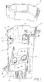
- the engine compartment can consists of a total of three can parts, namely initially a housing 10 to be fixed in the engine compartment, the shell-shaped is designed and its shell opening 13 by means of a cover 20 is lockable.
- the housing has 10 a large cutout extending over two wall parts 15, the in use of a visible from Fig. 3 to 5 slide 30 is closed.
- the slider 30 consists of a cranked in itself Plate 33 and thus creates the two adjacent wall zones 11, 12 of the housing 10 continuing further housing part, which thus forms the third can part mentioned.
- the housing 10 has mounting holes 14 for fastening it in the area of the engine compartment.
- the interior of the can is for arrangement of components and for inserting and exporting electrical cables in the upwardly open housing cutouts 16, 17 easily accessible.
- the inside of the can can be just as convenient, through the cutout 15, For example, be equipped with couplings, fuses, relays in a dash-dotted line in Fig. 1 carrier 18 for electrical Components can be summarized.
- One edge of the beam is over Plug connections positioned inside the one housing wall, for what the housing-side elements 24 in the open cutout 15 from FIG. 2 are recognizable.
- the opposite carrier edge 19 is supported against it on a bracket formed on the inner surface of the wall zone 11 there 29 from.
- a locking mechanism 28 which here from a resilient tongue is provided with an end latch bolt.
- the assembly of the can with the pre-assembled carrier 18 can thus be convenient from the shell opening 13 because in this direction both the plug connection 24 and the locking mechanism 28 automatically put into effect.
- the resilient tongue of the locking mechanism 28 can be also operate manually from the shell opening 13 without further ado, if the carrier 18 is to be dismantled.
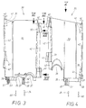
- the slide 30 When the housing 10 is permanently installed, the slide 30 can also be easily moved and quickly assemble and disassemble, the slider 30 in its Installation position is held extremely reliably. From yet Apart from details to be described in more detail, the assembly takes place of the slider 30 in the cutout 15 essentially in the direction indicated by the arrow 34 thrust direction illustrated in Fig. 1. This direction of thrust is 34 also shown in Figs. 3 and 4.
- This simple, reliable handling the slide 30 arises because of the special design of the slide side Profiles 40 on the one hand and housing-side counter profiles 50 on the other.
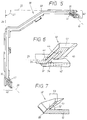
- the profiles 40 are located on the two, pointing in the direction of thrust Plate edge surfaces 31, 32, also called plate edges below, as best seen in Fig. 5.
- the housing side Counter profiles 50 are located on the longitudinal edges mentioned 21, 22 of section 15 and have the following, best seen in FIG. 7 Appearance.
- the counter profile 50 is, according to FIG. 7, by a V-like bending of wall parts creates, which is why a bent back V-leg 51 arises, which is continuous, but one Continuously changing V-profile to be described in more detail having.
- This free V-leg 51 is to be referred to as "guide leg” be named.
- the other V-leg is from the respective wall zone 12 self-formed.
- the V-apex forms the longitudinal edge 22 in each case or 21 of the cutout 15.
- the angle of inclination is also 52 of the V-profile, which, however, like the perspective View of Fig. 7 shows along edge 22 to the lower end of the Counter profile 50 can reduce down.
- the depth also changes 53 of the V-groove.
- the slide-side profile 40 initially consists of two different ones Profile elements 41, 42, the shape of which can best be seen in FIG. 6 is.
- these two profile elements 41, 42 are not continuous, but trained in the form of sections and should, because of their still special profile shape to be described in more detail, hereinafter briefly “hook section” at 41 and “inguinal section” at 42.
- This Sections 41, 42 are arranged in height offset from one another, to be precise preferably alternating with each other.
- the hook section 41 consists, as is the case in the cut in FIG. 6 can be seen from a protruding the plate edge 32 of the slide U-like hook profile, which has a hook opening 44.
- the hook opening 44 is variably profiled in the direction of the section and serves in the coupling case for receiving the guide leg 51.
- Der Hook section 41 is therefore at an angle of inclination 52 of the housing Guide leg 51 corresponding complementary angle 43 to Level 25 of the adjacent slide plate 33 is arranged.
- the strip section 42 consists of one opposite protruding the plate edge 33, but parallel to the plane of the slide plate 33 running last profile, which, for the sake of clarity, hatched in Fig. 6.
- the strip section 42 is namely 3, 4 can be seen, always offset in height to the hook portion 41 arranged, which is why it is not covered by the cut in Fig. 6 becomes.
- the two sections close in the vertical projection of FIG. 6 41, 42 but a V-shaped receptacle 54 between them, which the V-shaped counter profile 50 is adapted.
- the two sections 41, 42 face each other like claws.
- the two are Sections 41, 42 are always arranged alternately with one another on the two plate edges 31, 32 in a mutually opposing manner. Seen in the direction of insertion 34 of Fig. 3 and 4, is located on the a plate edge 32 first a hook portion 41, while on the opposite another panel edge 31 is initially arranged a strip section 42 is. Only then does a strip section follow on the first-mentioned plate edge 32 42, while on the opposite second plate edge 31 the first hook section 41 connects there. In total, both plate edges 31, 32 each provided with two hook sections 41, between which each have a strip section 42 different from one another Length is arranged. 3, 4, all sections are located 41, 42 of the edges 31, 32 on both sides in height offset from one another, what when inserting 34 a favorable, offset consequence of the clutch engagement conditionally.
- the hook portion 41 in turn in two differently profiled sections 46, 47 structured. Seen in the coupling-effective insertion direction 34, is located on the hook portion 41 is initially conical in the longitudinal direction profiled initial piece 47, which is then a uniformly profiled continuous end piece 46 connects.
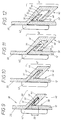
- the appearance of the profiles results from FIGS. 9 to 12, which, as already mentioned, is longitudinal sections IX to XII indicated in FIG. 8 have been carried out and the already coupled state with the counter profile 20 illustrate. 8 to 12 show that at the upper end of the slide 30 located hook section 41 and the height-offset strip section 42 of the profile 40.
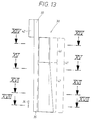
- FIGS. 13 and 14 show in analogy to 8 to 12, the corresponding ratios in the 3 and 4 each leading lower hook portion 41 when there the corresponding lower area is coupled by the counter profile 50 is.
- the previous description is therefore essentially valid, but are determine the following deviations.
- the slide plate 33 shown in Fig. 5 has a given space appropriately cranked shape in the engine compartment.
- Plate 33 is not only large-scale, but even extends over a corner area of the finished can.
- the two plate edges 31, 32 can easily in the different lines indicated by dash-dotted lines in FIG. 5 Levels 25, 26 lie and z. B., as in the present case, a enclose right angle 27 with each other.
- the on the two plate edges 31, 32 located hook sections 41 can be in the two about parallel planes 38, 39 of FIG. 2, but have, related to the adjacent areas of the plate 33, each to the outside.
- the guide leg 51 of the housing side Counter profile 50 so there is a mutual claw, through which the two-sided longitudinal edges shown in FIG. 1 or 2 21, 22 of section 15 can be drawn against each other.
- the slide 30 is locked by a locking mechanism Housing 10 held.
- Serve z. B. the lower end 59 of Slider 30 protruding tongues 57, 58, which with not recognizable, on the inner surface of the housing below the inner edge 23 of FIG. 1 located locking projections interact.
- the tongues 57, 58 have two height-different openings 61, 62, which a pre-locking position and a final stop position of this locking mechanism.
- the elements of this Latches can, however, be released from each other again, if for the purpose of disassembly the slide 30, one in the lifting direction, in the direction of the arrows 60 3 and 4 effective force is exerted, that of the above Insertion direction 34 is opposite.
- the slide 30 can therefore be vertically out of the housing towards the shell opening 13 10 pull out.
- the counter profile 50 also acts when it is pulled out 60 like a guide rail for the slide-side profile elements 41, 42.
- the slide 30 has at its lower end 35 a stepped edge strip 59, which in the coupling case behind the inner edge 23 of the housing cutout 15 of FIGS. 1 and 2 moves.
- the above-described outbreaks 37 for the passage of electrical lines at the lower end 35 of the slide also pass through this edge strip 59.
- the game mentioned in claim 16 is a special one easy assembly of slide 30 in housing 10 possible. This also applies to disassembly.
Landscapes
- Engineering & Computer Science (AREA)
- Mechanical Engineering (AREA)
- Casings For Electric Apparatus (AREA)
- Insertion, Bundling And Securing Of Wires For Electric Apparatuses (AREA)
- Coupling Device And Connection With Printed Circuit (AREA)
- Details Of Connecting Devices For Male And Female Coupling (AREA)
Description
- Fig. 1
- eine Vorderansicht eines im Motorraum zu befestigenden Gehäuses bei entferntem Schieber und bei vom Gehäuse abgehobenen Deckel, der dort ebenfalls in Vorderansicht gezeigt ist,
- Fig. 2
- eine Seitenansicht des Gehäuses und des abgehobenen Deckels von Fig. 1,
- Fig. 3
- die Vorderansicht eines als in sich verkröpfte Platte ausgebildeten Schiebers für das Gehäuse von Fig. 1,
- Fig. 4
- die entsprechende Seitenansicht des Schiebers von Fig. 3,
- Fig. 5
- die Draufsicht auf den Schieber von Fig. 3 bzw. 4 in Blickrichtung des Pfeils V von Fig. 4,
- Fig. 6
- in Vergrößerung eine Schnittansicht durch den Plattenrand des Schiebers von Fig. 3 längs der dortigen Schnittlinie VI-VI,
- Fig. 7
- in entsprechender Vergrößerung eine Schnittansicht durch die Längskante des Ausschnitts vom Gehäuse längs der Schnittlinie VII-VII von Fig. 2,
- Fig. 8
- in Vergrößerung die Endansicht des am oberen Plattenrand des Schiebers befindlichen Hakenabschnitts in Blickrichtung des Pfeils VIII von Fig. 3,
- Fig. 9, 10, 11 und 12
- vier zueinander höhenvestzte Querschnitte durch den oberen Hakenabschnitt des Schiebers von Fig. 8 längs der dortigen Schnittlinien IX, X, XI bzw. XII, nachdem seine beiden Profilelemente mit dem entsprechenden Gegenprofil des Gehäuseausschnitts in Eingriff gebracht worden sind,
- Fig. 13
- in einer der Fig. 8 entsprechenden vergrößerten Darstellung des am unteren Plattenrand des Schiebers befindlichen Hakenabschnitts die Endansicht in Blickrichtung des Pfeils VIII von Fig. 3 und
- Fig. 14, 15, 16 und 17,
- analog zu den Schnitten von Fig. 9 bis 12, höhenversetzte Querschnitte durch den in Fig. 13 gezeigten Hakenabschnitt, wenn dieser mit dem entsprechenden Gegenprofil des Gehäuses in Eingriff gekommen ist, und zwar längs der in Fig. 13 eingezeichneten vier Schnittlinien XIV bis XVII.
- 10
- Gehäuse
- 11
- erste Wandzone von 10
- 12
- zweite Wandzone von 10
- 13
- Schalenöffnung
- 14
- Montageloch für 10
- 15
- Ausschnitt in 10
- 16
- Ausbruch von 10 bei 23
- 17
- Ausbruch von 10 bei 23
- 18
- Träger für elektrische Bauteile
- 19
- Trägerrand von 18
- 20
- Deckel
- 21
- erste Längskante von 15 bei 11
- 22
- zweite Längskante von 15 bei 12
- 23
- innere Kante von 15
- 24
- Steckverbindungselement für 18 (Fig. 2)
- 25
- Ebene von 31 (Fig. 5)
- 26
- Ebene von 32 (Fig. 5)
- 27
- Winkel zwischen 25, 26
- 28
- Riegelgesperre an 29 (Fig. 1)
- 29
- Konsole für 19 (Fig. 1)
- 30
- Schieber
- 31
- erster Plattenrand von 30
- 32
- zweiter Plattenrand von 30
- 33
- verkröpfte Platte von 30
- 34
- Einschubrichtungs-Pfeil von 30
- 35
- Unterende von 30
- 36
- erster Ausbruch in 33
- 37
- weiterer Ausbruch in 33
- 38
- Ebene von 41 bei 31 (Fig. 5)
- 39
- Ebene von 41 bei 32 (fig. 5)
- 40
- Profil von 30
- 41
- erstes Profilelement von 40, Hakenabschnitt
- 42
- zweites Profilelement von 40, Leistenabschnitt
- 43
- Abwinkelung von 41, Komplementärwinkel zu 52 (Fig. 6)
- 44
- Hakenöffnung von 41
- 45
- Hakenende von 41
- 46
- erstes Teilstück von 41, gleichförmiges Endstück
- 47
- zweites Teilstück von 41, konisches Anfangsstück
- 48
- U-Tiefe von 44
- 49
- U-Weite von 44
- 50
- V-artiges Gegenprofil bei 10
- 51
- Führungsschenkel von 50
- 52
- Neigungswinkel an der Innenfläche von 51 gegenüber 12
- 52'
- Neigungswinkel an der Außenfläche von 51 gegenüber 12
- 53
- V-Nuttiefe von 50
- 54
- V-förmige Aufnahme zwischen 41, 42 (Fig. 6)
- 55
- Schenkellänge von 51
- 56
- Schenkeldicke von 51
- 57
- Zunge des Rastgesperres für 30
- 58
- Zunge des Rastgesperres für 30
- 59
- abgesetzter Randstreifen bei 35
- 60
- Ausheberichtungs-Pfeil (Fig. 3, 4)
- 61
- Öffnung für Vorraststellung in 57, 58
- 62
- Öffnung für Endraststellung in 57, 58
- 63
- Finger an 10
Claims (17)
- Motorraumdose zur Aufnahme elektrischer Bauteile, wie Kupplungen, Sicherungen, Relais od. dgl., und deren Leitungsanschlüsse,mit einem schalenförmigen eine Schalenöffnung (13) aufweisenden, im Motorraum befestigbaren Gehäuse (10), welches zum Durchführen von elektrischen Leitungen Durchbrüche (16, 36; 17, 37) in seiner Wand aufweist,mit einem die Schalenöffnung (13) des Gehäuses (10) verschließenden Deckel (20),mit einem von der Schalenöffnung (13) ausgehenden Ausschnitt (15) in der Gehäusewand und mit einem den Ausschnitt (15) verschließenden plattenförmigen Schieber (30), der vom Gehäuse (10) lösbar ist,
wobei der Schieber (30) an seinen beiden, in Schubrichtung (34) weisenden Plattenrändern (31, 32) Profile (40) aufweist, denen Gegenprofile (50) in jenen Wandzonen (11, 12) des Gehäuses (10) zugeordnet sind, welche den Ausschnitt (15) beidlängsseitig begrenzen,
dadurch gekennzeichnetdaß die beiden Gegenprofile (50) am Gehäuse (10) V-artig ausgebildet sind, deren einer V-Schenkel jeweils von den beiden Wandzonen (11, 12) des Gehäuses selbst erzeugt ist, deren beide V-Scheitel die beiden Längskanten (21, 22) des Ausschnitts (15) bestimmen und deren anderer freier V-Schenkel jeweils, von der Ausschnitt-Längskante (21, 22) wegweisend, zurückgebogen ist und jeweils einen durchgehenden Führungsschenkel (51) für das ihm zugeordnete Profile (40) vom Schieber (30) bildet,und daß die Profile (40) an den beiden Plattenrandflächen (31, 32) des Schiebers (30) jeweils aus zwei unterschiedlichen Profilelementen kombiniert sind,
wobei das erste Profilelement aus einem die Plattenrandfläche (31 bzw. 32) des Schiebers (30) überragenden, abgewinkelt zur Ebene (25, 26) der Plattenrandfläche (31, 32) verlaufenden U-artigen Hakenprofil (41) besteht,während das zweite Profilelement von einem vorspringenden, parallel zur Plattenrandfläche (32, 31) verlaufenden Leistenprofil (42) gebildet ist, welches - in längsrandseitiger Projektion gesehen - mit dem Hakenprofil (41) eine V-förmige Aufnahme (54) für das Gegenprofil (50) des Gehäuses (10) bildet. - Dose nach Anspruch 1, dadurch gekennzeichnet, daß die beiden Profilelemente (41, 42) an beiden Plattenrandflächen (31, 32) abschnittweise und miteinander im Wechsel angeordnet sind,und, in Einschubrichtung (34) gesehen, an der einen Plattenrandfläche (32) des Schiebers (30) zuerst ein Abschnitt des Hakenprofils (41) angeordnet ist, dem sich dann ein Abschnitt des Leistenprofils (42) anschließt,aber an der Plattenrandfläche (31) des Schiebers (30), umgekehrt, sich zunächst ein Abschnitt des Leistenprofils (42) befindet, dem ein Abschnitt des Hakenabprofils (41) folgt.
- Dose nach Anspruch 1 oder 2, dadurch gekennzeichnet, daß der Abschnitt des Hakenprofils (41) des Schiebers (30) seinerseits aus zwei unterschiedlich profilierten Teilstücken (46, 47) besteht, nämlich, in Einschubrichtung (34) gesehen, zunächst aus einem konisch profilierten Anfangsstück (47) und dann aus einem gleichförmig profilierten Endstück (46), (Fig. 8 und 13).
- Dose nach einem oder mehreren der Ansprüche 1 bis 3, dadurch gekennzeichnet, daß im konischen Anfangsstück (47) die Hakenöffnung (44) des U-artigen Hakenprofils (41) sich sowohl hinsichtlich der lichten U-Weite (49) als auch hinsichtlich der lichten U-Tiefe (53) zum Endstück (46) hin verjüngt, (Fig. 9 bis 12).
- Dose nach einem oder mehreren der Ansprüche 1 bis 4, dadurch gekennzeichnet, daß in Einschublage des Schiebers (30) die Innenfläche seines Abschnitts mit Leistenprofil (42) einerseits und die Stirnfläche am Hakenende (45) seines Abschnitts mit Hakenprofil (41) andererseits die Innen- und Außenfläche der zum Gegenprofil (50) des Gehäuses (10) gehörenden Wandzone (12) berühren, (Fig. 9 bis 12).
- Dose nach einem oder mehreren der Ansprüche 1 bis 5, dadurch gekennzeichnet, daß in Einschublage des Schiebers (30) gesehen, der Führungsschenkel (51) vom Gegenprofil (50) des Gehäuses (10) zwar im Endstück (46) des Abschnitts mit Hakenprofil (41) mit den Innenflächen des U-förmigen Hakenprofils in Berührung steht, aber zu den Innenflächen vom konischen Anfangsstück (47) des Abschnitts mit Hakenprofil (41) wenigstens bereichsweise ein seitliches Spiel aufweist, (Fig. 9 und 12).
- Dose nach einem oder mehreren der Ansprüche 1 bis 6, dadurch gekennzeichnet, daß - in Einschubrichtung (34) des Schiebers (30) gesehen - der Führungsschenkel (51) des V-artigen Gegenprofils (50) ein sich hinsichtlich der Schenkellänge (55) und/oder der Schenkeldicke (56) und/oder der Schenkelneigung (52, 52') kontinuierlich veränderndes Schenkelprofil aufweist.
- Dose nach Anspruch 7, dadurch gekennzeichnet, daß die V-Nut des Gegenprofils (50) am inneren Ende des Gehäuse-Ausschnitts (15) eine kleinere Nuttiefe (53) aufweist als am gegenüberliegenden äußeren Ende des Ausschnitts, (Fig. 9 und 17).
- Dose nach Anspruch 7 oder 8, dadurch gekennzeichnet, daß der Führungsschenkel (51) des V-artigen Gegenprofils (50) eine vom inneren Ende des Ausschnitts (15) aus zum gegenüberliegenden äußeren Ausschnitt-Ende hin keilförmig anwachsende Schenkeldicke (56) aufweist, (Fig. 12 und 15).
- Dose nach einem oder mehreren der Ansprüche 1 bis 9, dadurch gekennzeichnet, daß an beiden Plattenrandflächen (31, 32) des Schiebers (30) jeweils zwei Abschnitte mit Hakenprofil (41) sitzen, zwischen denen ein Abschnitt mit Leistenprofil (42) angeordnet ist, (Fig. 3 und 4).
- Dose nach einem oder mehreren der Ansprüche 1 bis 10 , dadurch gekennzeichnet, daß am, in Einschubrichtung (34) des Schiebers (30) gesehen, oberen Ende der beiden Plattenrandflächen (31, 32) des Schiebers (30) jeweils Abschnitte mit Hakenprofil (41) sitzen, (Fig. 3, 4).
- Dose nach einem oder mehreren der Ansprüche 1 bis 11, dadurch gekennzeichnet, daß die Dose in einer zu Anspruch 1 spiegelbildlichen Weise ausgebildet ist, und zwar die Plattenrandflächen des Schiebers V-artig gegeneinander rückgebogen sind und jeweils einen durchgehenden Führungsschenkel bilden, während die am Gehäuse befindlichen Gegenprofile aus im wesentlichen im Wechsel zueinander angeordneten Abschnitten mit U-artigem Hakenprofil und aus parallel zur Wandzone verlaufenden Abschnitten mit Leistenprofil bestehen.
- Dose nach einem oder mehreren der Ansprüche 1 bis 12, dadurch gekennzeichnet, daß der Schieber (30) eine unebene, vorzugsweise in sich verkröpfte Platte (33) aufweist und seine beiden profilierten Plattenflächen (31, 32) im Winkel (27) zueinander verlaufen, (Fig. 5).
- Dose nach einem oder mehreren der Ansprüche 1 bis 13, dadurch gekennzeichnet, daß sämtliche Durchbrüche zum Durchführen von elektrischen Leitungen aus einander paarweise komplementierenden Ausbrüchen (16, 36; 17, 37) an der inneren Kante (23) des Gehäuse-Ausschnitts (15) einerseits und dem unteren Plattenrand (35) des Schiebers (30) andererseits bestehen, (Fig. 1 bis 4).
- Dose nach einem oder mehreren der Ansprüche 1 bis 14, dadurch gekennzeichnet, daß zwischen der inneren Kante (23) des Gehäuse-Ausschnitts (15) einerseits und dem unteren Plattenrand (35) des Schiebers (30) andererseits ein Rastgesperre (57, 58) angeordnet ist, welches ggf. eine Vorraststellung (61) aufweist und durch eine auf den Schieber (30) im Ausschubsinne (60) wirksame Kraft lösbar ist, (Fig. 2, 3).
- Dose nach einem oder mehreren der Ansprüche 1 bis 15, dadurch gekennzeichnet, daß ein Träger (18) für elektrische Bauelemente, wie ein Sicherungs- und/oder Relaisträger, zwar an seinem einen Trägerrand über Steckverbindungen (24) an der Gehäusewand positioniert ist, aber mit seinem gegenüberliegenden Trägerrand (19) sich an einer Konsole (29) der Gehäusewand (11) abstützt und an der Konsole (29) ggf. ein den Träger fixierendes Riegelsperre (28) sitzt, welches von der Schalenöffnung (13) aus manuell in Freigabeposition überführbar ist, (Fig. 1).
- Dose nach einem oder mehreren der Ansprüche 1 bis 16, dadurch gekennzeichnet, daß das Schenkelprofil des gehäuseseitigen Führungsschenkels (51) gegenüber der Öffnungsweite der ihn aufnehmenden Öffnung (44) im Schieber (30) zu Beginn der Einschubbewegung (34) ein größeres Spiel aufweist, als in voller Einschublage des Schiebers (30).
Applications Claiming Priority (2)
| Application Number | Priority Date | Filing Date | Title |
|---|---|---|---|
| DE4431859 | 1994-09-07 | ||
| DE4431859A DE4431859C1 (de) | 1994-09-07 | 1994-09-07 | Dose zum Einbau in einem Motorraum und zur Aufnahme elektrischer Bauteile und deren Leitungsanschlüsse |
Publications (3)
| Publication Number | Publication Date |
|---|---|
| EP0700807A2 EP0700807A2 (de) | 1996-03-13 |
| EP0700807A3 EP0700807A3 (de) | 1998-11-04 |
| EP0700807B1 true EP0700807B1 (de) | 2000-11-08 |
Family
ID=6527635
Family Applications (1)
| Application Number | Title | Priority Date | Filing Date |
|---|---|---|---|
| EP95113066A Expired - Lifetime EP0700807B1 (de) | 1994-09-07 | 1995-08-19 | Motorraumdose zur Aufnahme elektrischer Bauteile und deren Leitungsanschlüsse |
Country Status (3)
| Country | Link |
|---|---|
| EP (1) | EP0700807B1 (de) |
| DE (2) | DE4431859C1 (de) |
| ES (1) | ES2152351T3 (de) |
Families Citing this family (1)
| Publication number | Priority date | Publication date | Assignee | Title |
|---|---|---|---|---|
| JP3257469B2 (ja) * | 1997-09-24 | 2002-02-18 | 住友電装株式会社 | 電気接続箱 |
Family Cites Families (4)
| Publication number | Priority date | Publication date | Assignee | Title |
|---|---|---|---|---|
| GB1478892A (en) * | 1973-12-05 | 1977-07-06 | Cavis Cavetti Isolati Spa | Junction box for motor vehicle electrical systems |
| DE3414907A1 (de) * | 1984-04-19 | 1985-10-31 | Zünderwerk Rudolf Brüggemann, 5300 Bonn | Kabel- oder leiterverbindungsdose, insbesondere fuer kraftfahrzeuge |
| DE4142525C1 (de) * | 1991-12-21 | 1993-06-03 | Kabelwerke Reinshagen Gmbh, 5600 Wuppertal, De | |
| DE4240381A1 (de) * | 1992-12-01 | 1994-06-09 | Licentia Gmbh | Elektromotor, insbesondere Kommutatormotor |
-
1994
- 1994-09-07 DE DE4431859A patent/DE4431859C1/de not_active Expired - Fee Related
-
1995
- 1995-08-19 DE DE59508836T patent/DE59508836D1/de not_active Expired - Fee Related
- 1995-08-19 ES ES95113066T patent/ES2152351T3/es not_active Expired - Lifetime
- 1995-08-19 EP EP95113066A patent/EP0700807B1/de not_active Expired - Lifetime
Also Published As
| Publication number | Publication date |
|---|---|
| DE59508836D1 (de) | 2000-12-14 |
| EP0700807A3 (de) | 1998-11-04 |
| ES2152351T3 (es) | 2001-02-01 |
| EP0700807A2 (de) | 1996-03-13 |
| DE4431859C1 (de) | 1996-01-04 |
Similar Documents
| Publication | Publication Date | Title |
|---|---|---|
| DE69607404T2 (de) | Elektrischer Verbinder mit Kontaktverriegelungsteil und verschiebbarem Nocken | |
| DE69714332T2 (de) | Abgeschirmter Verbinder mit Stecker und Buchse und mit einem Verriegelungs-/Entriegelungsorgan | |
| DE2925938A1 (de) | Elektrischer flachsteckverbinder | |
| DE19860812A1 (de) | Lichtwellenleiterkabelfähiges, metallisches Verlegungssystem | |
| DE10256463B4 (de) | Elektrisches Verbindergehäuse | |
| DE69214493T2 (de) | Sicherungshaltergehäuse modularer Struktur | |
| EP0390006B1 (de) | Elektrische Kupplungsvorrichtung | |
| DE69328466T2 (de) | Verbinder | |
| DE19509917C1 (de) | Vorrichtung zum Abscheiden von Kondensat mit Abscheiderelementen | |
| DE69200449T2 (de) | Tür für einen Elektroherd und ihr Einbauverfahren. | |
| DE3925010C2 (de) | Kabelkanal | |
| EP0592707B1 (de) | Abscheider für eine Einrichtung zum Be- und Entlüften von Räumen | |
| DE4431859C1 (de) | Dose zum Einbau in einem Motorraum und zur Aufnahme elektrischer Bauteile und deren Leitungsanschlüsse | |
| DE2850779C2 (de) | Türzarge zur Führung von elektrischen Leitern | |
| EP0386496B1 (de) | Heizkörperverkleidung | |
| EP0749180B1 (de) | Steckverbindergehäuse | |
| DE2953717C1 (de) | Vorrichtung zum Befestigen des winkelfoermigen Gehaeuses einer Eckumlenkung in Nuten eiens FLuegelrahmens | |
| DE69836574T2 (de) | Elektrischer Kasten | |
| DE69302158T2 (de) | Profileinrichtung für die Verkabelung elektrischer Apparate, und geeignetes Skelett und Rinne um eine solche Einrichtung zu bauen | |
| CH683807A5 (de) | Vorrichtung zur Aufnahme von Schallplatten-, Tonband- oder Videokassetten. | |
| DE3784840T2 (de) | Abzweigungszubehoer fuer verkabelungsrohr. | |
| DE202011100808U1 (de) | Kabelkanal | |
| DE2729259A1 (de) | Elektrisches geraet | |
| DE9403212U1 (de) | Gehäuse zur Aufnahme von bestückten Leiterplatten | |
| DE8814029U1 (de) | Gurtbares Kunststoffgehäuse |
Legal Events
| Date | Code | Title | Description |
|---|---|---|---|
| PUAI | Public reference made under article 153(3) epc to a published international application that has entered the european phase |
Free format text: ORIGINAL CODE: 0009012 |
|
| AK | Designated contracting states |
Kind code of ref document: A2 Designated state(s): DE ES FR GB IT |
|
| PUAL | Search report despatched |
Free format text: ORIGINAL CODE: 0009013 |
|
| AK | Designated contracting states |
Kind code of ref document: A3 Designated state(s): DE ES FR GB IT |
|
| 17P | Request for examination filed |
Effective date: 19990504 |
|
| GRAG | Despatch of communication of intention to grant |
Free format text: ORIGINAL CODE: EPIDOS AGRA |
|
| 17Q | First examination report despatched |
Effective date: 19990930 |
|
| GRAG | Despatch of communication of intention to grant |
Free format text: ORIGINAL CODE: EPIDOS AGRA |
|
| GRAH | Despatch of communication of intention to grant a patent |
Free format text: ORIGINAL CODE: EPIDOS IGRA |
|
| GRAH | Despatch of communication of intention to grant a patent |
Free format text: ORIGINAL CODE: EPIDOS IGRA |
|
| GRAA | (expected) grant |
Free format text: ORIGINAL CODE: 0009210 |
|
| ITF | It: translation for a ep patent filed | ||
| AK | Designated contracting states |
Kind code of ref document: B1 Designated state(s): DE ES FR GB IT |
|
| GBT | Gb: translation of ep patent filed (gb section 77(6)(a)/1977) |
Effective date: 20001108 |
|
| REF | Corresponds to: |
Ref document number: 59508836 Country of ref document: DE Date of ref document: 20001214 |
|
| ET | Fr: translation filed | ||
| REG | Reference to a national code |
Ref country code: ES Ref legal event code: FG2A Ref document number: 2152351 Country of ref document: ES Kind code of ref document: T3 |
|
| PLBE | No opposition filed within time limit |
Free format text: ORIGINAL CODE: 0009261 |
|
| STAA | Information on the status of an ep patent application or granted ep patent |
Free format text: STATUS: NO OPPOSITION FILED WITHIN TIME LIMIT |
|
| 26N | No opposition filed | ||
| REG | Reference to a national code |
Ref country code: GB Ref legal event code: IF02 |
|
| PGFP | Annual fee paid to national office [announced via postgrant information from national office to epo] |
Ref country code: ES Payment date: 20030829 Year of fee payment: 9 |
|
| PGFP | Annual fee paid to national office [announced via postgrant information from national office to epo] |
Ref country code: GB Payment date: 20030901 Year of fee payment: 9 |
|
| PG25 | Lapsed in a contracting state [announced via postgrant information from national office to epo] |
Ref country code: GB Free format text: LAPSE BECAUSE OF NON-PAYMENT OF DUE FEES Effective date: 20040819 |
|
| PG25 | Lapsed in a contracting state [announced via postgrant information from national office to epo] |
Ref country code: ES Free format text: LAPSE BECAUSE OF NON-PAYMENT OF DUE FEES Effective date: 20040820 |
|
| GBPC | Gb: european patent ceased through non-payment of renewal fee |
Effective date: 20040819 |
|
| PGFP | Annual fee paid to national office [announced via postgrant information from national office to epo] |
Ref country code: FR Payment date: 20050809 Year of fee payment: 11 |
|
| PGFP | Annual fee paid to national office [announced via postgrant information from national office to epo] |
Ref country code: DE Payment date: 20050811 Year of fee payment: 11 |
|
| REG | Reference to a national code |
Ref country code: ES Ref legal event code: FD2A Effective date: 20040820 |
|
| PGFP | Annual fee paid to national office [announced via postgrant information from national office to epo] |
Ref country code: IT Payment date: 20060831 Year of fee payment: 12 |
|
| PG25 | Lapsed in a contracting state [announced via postgrant information from national office to epo] |
Ref country code: DE Free format text: LAPSE BECAUSE OF NON-PAYMENT OF DUE FEES Effective date: 20070301 |
|
| REG | Reference to a national code |
Ref country code: FR Ref legal event code: ST Effective date: 20070430 |
|
| PG25 | Lapsed in a contracting state [announced via postgrant information from national office to epo] |
Ref country code: FR Free format text: LAPSE BECAUSE OF NON-PAYMENT OF DUE FEES Effective date: 20060831 |
|
| PG25 | Lapsed in a contracting state [announced via postgrant information from national office to epo] |
Ref country code: IT Free format text: LAPSE BECAUSE OF NON-PAYMENT OF DUE FEES Effective date: 20070819 |