EP0700783B1 - Farbstrahlaufzeichnungsgerät - Google Patents
Farbstrahlaufzeichnungsgerät Download PDFInfo
- Publication number
- EP0700783B1 EP0700783B1 EP95110365A EP95110365A EP0700783B1 EP 0700783 B1 EP0700783 B1 EP 0700783B1 EP 95110365 A EP95110365 A EP 95110365A EP 95110365 A EP95110365 A EP 95110365A EP 0700783 B1 EP0700783 B1 EP 0700783B1
- Authority
- EP
- European Patent Office
- Prior art keywords
- discharge
- vibrating plate
- jet recording
- piezoelectric vibrating
- ink jet
- Prior art date
- Legal status (The legal status is an assumption and is not a legal conclusion. Google has not performed a legal analysis and makes no representation as to the accuracy of the status listed.)
- Expired - Lifetime
Links
- 230000005499 meniscus Effects 0.000 claims description 49
- 238000006073 displacement reaction Methods 0.000 claims description 30
- 238000007599 discharging Methods 0.000 claims description 20
- 238000000034 method Methods 0.000 claims description 17
- 230000004044 response Effects 0.000 claims description 8
- 230000000063 preceeding effect Effects 0.000 claims 1
- 239000003990 capacitor Substances 0.000 description 27
- 230000003068 static effect Effects 0.000 description 7
- MCMNRKCIXSYSNV-UHFFFAOYSA-N Zirconium dioxide Chemical compound O=[Zr]=O MCMNRKCIXSYSNV-UHFFFAOYSA-N 0.000 description 6
- 230000015572 biosynthetic process Effects 0.000 description 4
- 238000013016 damping Methods 0.000 description 4
- 229910052451 lead zirconate titanate Inorganic materials 0.000 description 4
- HFGPZNIAWCZYJU-UHFFFAOYSA-N lead zirconate titanate Chemical compound [O-2].[O-2].[O-2].[O-2].[O-2].[Ti+4].[Zr+4].[Pb+2] HFGPZNIAWCZYJU-UHFFFAOYSA-N 0.000 description 4
- 238000010586 diagram Methods 0.000 description 3
- 239000000758 substrate Substances 0.000 description 3
- 238000004026 adhesive bonding Methods 0.000 description 2
- 230000006399 behavior Effects 0.000 description 2
- 230000000295 complement effect Effects 0.000 description 2
- 230000007613 environmental effect Effects 0.000 description 2
- 238000004519 manufacturing process Methods 0.000 description 2
- 230000007935 neutral effect Effects 0.000 description 2
- 125000006850 spacer group Chemical group 0.000 description 2
- 239000000853 adhesive Substances 0.000 description 1
- 238000005452 bending Methods 0.000 description 1
- 239000000919 ceramic Substances 0.000 description 1
- 230000008602 contraction Effects 0.000 description 1
- 238000005260 corrosion Methods 0.000 description 1
- 230000007797 corrosion Effects 0.000 description 1
- 230000001419 dependent effect Effects 0.000 description 1
- 238000005304 joining Methods 0.000 description 1
- 239000000463 material Substances 0.000 description 1
- 229910001220 stainless steel Inorganic materials 0.000 description 1
- 239000010935 stainless steel Substances 0.000 description 1
- 230000001360 synchronised effect Effects 0.000 description 1
- 230000002195 synergetic effect Effects 0.000 description 1
Images



Classifications
-
- B—PERFORMING OPERATIONS; TRANSPORTING
- B41—PRINTING; LINING MACHINES; TYPEWRITERS; STAMPS
- B41J—TYPEWRITERS; SELECTIVE PRINTING MECHANISMS, i.e. MECHANISMS PRINTING OTHERWISE THAN FROM A FORME; CORRECTION OF TYPOGRAPHICAL ERRORS
- B41J2/00—Typewriters or selective printing mechanisms characterised by the printing or marking process for which they are designed
- B41J2/005—Typewriters or selective printing mechanisms characterised by the printing or marking process for which they are designed characterised by bringing liquid or particles selectively into contact with a printing material
- B41J2/01—Ink jet
- B41J2/015—Ink jet characterised by the jet generation process
- B41J2/04—Ink jet characterised by the jet generation process generating single droplets or particles on demand
- B41J2/045—Ink jet characterised by the jet generation process generating single droplets or particles on demand by pressure, e.g. electromechanical transducers
- B41J2/04501—Control methods or devices therefor, e.g. driver circuits, control circuits
- B41J2/04516—Control methods or devices therefor, e.g. driver circuits, control circuits preventing formation of satellite drops
-
- B—PERFORMING OPERATIONS; TRANSPORTING
- B41—PRINTING; LINING MACHINES; TYPEWRITERS; STAMPS
- B41J—TYPEWRITERS; SELECTIVE PRINTING MECHANISMS, i.e. MECHANISMS PRINTING OTHERWISE THAN FROM A FORME; CORRECTION OF TYPOGRAPHICAL ERRORS
- B41J2/00—Typewriters or selective printing mechanisms characterised by the printing or marking process for which they are designed
- B41J2/005—Typewriters or selective printing mechanisms characterised by the printing or marking process for which they are designed characterised by bringing liquid or particles selectively into contact with a printing material
- B41J2/01—Ink jet
- B41J2/015—Ink jet characterised by the jet generation process
- B41J2/04—Ink jet characterised by the jet generation process generating single droplets or particles on demand
- B41J2/045—Ink jet characterised by the jet generation process generating single droplets or particles on demand by pressure, e.g. electromechanical transducers
- B41J2/04501—Control methods or devices therefor, e.g. driver circuits, control circuits
- B41J2/04541—Specific driving circuit
-
- B—PERFORMING OPERATIONS; TRANSPORTING
- B41—PRINTING; LINING MACHINES; TYPEWRITERS; STAMPS
- B41J—TYPEWRITERS; SELECTIVE PRINTING MECHANISMS, i.e. MECHANISMS PRINTING OTHERWISE THAN FROM A FORME; CORRECTION OF TYPOGRAPHICAL ERRORS
- B41J2/00—Typewriters or selective printing mechanisms characterised by the printing or marking process for which they are designed
- B41J2/005—Typewriters or selective printing mechanisms characterised by the printing or marking process for which they are designed characterised by bringing liquid or particles selectively into contact with a printing material
- B41J2/01—Ink jet
- B41J2/015—Ink jet characterised by the jet generation process
- B41J2/04—Ink jet characterised by the jet generation process generating single droplets or particles on demand
- B41J2/045—Ink jet characterised by the jet generation process generating single droplets or particles on demand by pressure, e.g. electromechanical transducers
- B41J2/04501—Control methods or devices therefor, e.g. driver circuits, control circuits
- B41J2/04581—Control methods or devices therefor, e.g. driver circuits, control circuits controlling heads based on piezoelectric elements
-
- B—PERFORMING OPERATIONS; TRANSPORTING
- B41—PRINTING; LINING MACHINES; TYPEWRITERS; STAMPS
- B41J—TYPEWRITERS; SELECTIVE PRINTING MECHANISMS, i.e. MECHANISMS PRINTING OTHERWISE THAN FROM A FORME; CORRECTION OF TYPOGRAPHICAL ERRORS
- B41J2/00—Typewriters or selective printing mechanisms characterised by the printing or marking process for which they are designed
- B41J2/005—Typewriters or selective printing mechanisms characterised by the printing or marking process for which they are designed characterised by bringing liquid or particles selectively into contact with a printing material
- B41J2/01—Ink jet
- B41J2/015—Ink jet characterised by the jet generation process
- B41J2/04—Ink jet characterised by the jet generation process generating single droplets or particles on demand
- B41J2/045—Ink jet characterised by the jet generation process generating single droplets or particles on demand by pressure, e.g. electromechanical transducers
- B41J2/04501—Control methods or devices therefor, e.g. driver circuits, control circuits
- B41J2/04588—Control methods or devices therefor, e.g. driver circuits, control circuits using a specific waveform
Definitions
- the present invention relates to an ink jet recording apparatus and in particular to an ink jet recording head.
- Ink jet recording apparatuses which use a piezoelectric vibrating plate as an actuator for producing an ink drop are classified into those which utilize axial displacement of a piezoelectric vibrating plate having a bar-like shape, and those which utilize deflection displacement of a piezoelectric vibrating plate having a plate-like shape.
- the former ones have an advantage of a high-speed operation, but have a problem in that it is difficult to mount a piezoelectric vibrating plate and hence the production cost is increased.
- a piezoelectric vibrating plate is stuck to a partial region of a vibrating plate constituting a pressurizing chamber, and the capacity of the pressurizing chamber is changed by deflection displacement of the piezoelectric vibrating plate, thereby producing an ink drop. Therefore, such apparatuses have advantages in that a large area of the pressurizing chamber can be displaced and an ink drop can stably be produced, and that the piezoelectric vibrating plate and the vibrating plate can simultaneously be formed and hence the production cost can be reduced. Since such apparatuses utilize deflection displacement, however, they have a drawback of a reduced damping force.
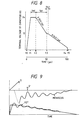
- the reduced damping force causes the vibrating plate to move in response to an ink flow generated after ink ejection, so that there occur vibration in the meniscus as shown in Fig. 9 and the vibration is continued for a long time period.
- minute ink drops D' or so-called satellites are produced.
- Prior art document EP 0 580 154 discloses an on-demand type ink-jet recording device which can reduce the length of ink droplets jetted from the nozzle openings, thereby forming spherical droplets and circular dots on the printed page. This is achieved by expanding a pressure generation chamber, to suck in ink, contracting the pressure generation chamber at a first speed for a certain time and then contracting the pressure generation chamber at a second speed that is larger than the first speed. As a result, ink can be jetted out continuously in such a manner that the ink at the end of the ink drop catches up with ink at the top of the ink drop, to thereby allow a spherical ink droplet to reach the recording paper.
- the object is solved by the ink jet recording head according to independent claims 1, 8 and 11 by an ink jet recording apparatus according to independent claim 12 and by an ink jet recording method according to independent claims 13, 20 and 23.
- the invention relates to an ink jet recording apparatus, and more particularly to an ink jet recording apparatus using a recording head in which a piezoelectric vibrating thin plate is stuck to a partial region of a pressurizing chamber communicated with a nozzle opening, and the pressurizing chamber is compressed by the piezoelectric vibrating plate to produce an ink drop.
- the word 'a charge time constant' means a reciprocal number of the voltage gradient with respect to time when charging
- 'a discharge time constant' means a reciprocal number of the voltage gradient with respect to time when discharging
- An ink jet recording apparatus comprises: an ink jet recording head which comprises a pressurizing chamber communicated with a nozzle opening and a common ink chamber, and a piezoelectric vibrating plate which is formed at a surface of the pressurizing chamber and deflection-displaced, the head being caused to eject an ink drop by the deflection displacement of the piezoelectric vibrating plate; a charging circuit which supplies a current to the piezoelectric vibrating plate in response to a print signal, thereby producing the deflection displacement for ink ejection, and which outputs a signal for holding a charge final voltage during a fixed time period after an end of charge; and a discharging circuit which has a first discharge time constant suitable for sucking meniscus formed immediately after ink ejection toward the pressurizing chamber, thereby preventing the meniscus from being ejected from the nozzle opening, which stops discharge in a range which is (n + 3/4) to (n + 1) times (where n is 1, 2, 3,..., or 8) a natural
- Fig. 1 shows an embodiment of an ink jet recording head according to the invention.
- the reference numeral 1 designates a driving unit configured by integrally fixing piezoelectric vibrating plates 3 which are made of PZT (lead zirconate titanate), to the surface of a vibrating plate 2 which is made of a thin plate of zirconia having a thickness of about 10 ⁇ m, in such a manner that the vibrating plates respectively oppose pressurizing chambers 4 which will be described later.
- PZT lead zirconate titanate
- the reference numeral 5 designates a spacer.
- through holes coincident in shape with the pressurizing chambers 4 are opened in a ceramics plate of zirconia (ZrO 2 ) or the like and having a thickness, for example, 150 ⁇ m suitable for the formation of the pressurizing chambers 4.
- ZrO 2 zirconia
- the reference numeral 8 designates a substrate which seals the other face of the pressurizing chambers 4.
- communicating holes 9 for connecting nozzle openings 31 to the pressurizing chambers 4 are opened in one end portion of the substrate on the side of the pressurizing chambers 4, and communicating holes 10 for connecting the pressurizing chambers 4 to a common ink chamber 19 are opened in the other end portion.
- the reference numeral 11 designates the unit fixing plate.
- the unit fixing plate the above-mentioned unit is fixed to a predetermined position of one face by an adhesive agent.
- Flow path restriction holes 12 having a flow resistance which is substantially equal to that of the nozzle openings 31 are opened at the interface between the communicating holes 10 and the common ink chamber 19.
- the flow path restriction holes serve as ink supply ports.
- communicating holes 13 connected to the nozzle openings 31 are opened at positions opposing the respective communicating holes 9.
- the reference numeral 15 designates a hot gluing film for joining the unit fixing plate 11 to a common ink chamber plate 18 which will be described later.
- a window 16 coincident with the common ink chamber 19, and communicating holes 17 for connecting the nozzle openings 31 to the pressurizing chambers 4 are opened.
- the reference numeral 18 designates the common ink chamber plate.
- the common ink chamber plate 18 includes a plate which has a thickness of, for example, 150 ⁇ m and suitable for the formation of the common ink chamber 19 and which is made of a corrosion-resistant material such as stainless steel.
- a through hole corresponding in shape to the common ink chamber 19, and communicating holes 21 for connecting the pressurizing chambers 4 to the nozzle openings 31 are opened in the common ink chamber plate.
- the reference numeral 23 designates a nozzle plate where the nozzle openings 31 are opened in one end portion on the side of the pressurizing chambers 4.
- the nozzle plate is adhered to the common ink chamber plate 18 by a hot gluing film 25 so that the nozzle openings 31 are connected to the respective pressurizing chambers 4 via the communicating holes 9, 13, 17, 21, and 26.
- the vibrating plate 2 when a drive signal wherein the voltage level is raised at a constant rate is applied to the piezoelectric vibrating plate 3, the vibrating plate 2 is deflected in such a manner that the portion on the side of the pressurizing chamber 4 is convex, thereby contracting the pressurizing chamber 4. This causes the ink in the pressurizing chamber 4 to reach the nozzle opening 31 via the communicating holes 9, 13, 17, 21, and 26, and an ink drop is ejected therefrom.
- the piezoelectric vibrating plate 3 When the voltage level of the drive signal is lowered at a constant rate after the ink drop formation, the piezoelectric vibrating plate 3 gradually returns to its original state so that the pressurizing chamber 4 is expanded. During this process, an amount of ink equal to that consumed by the ink drop formation flows from the common ink chamber 19 into the pressurizing chamber 4 via the flow path restriction hole 12.
- Fig. 2 shows an embodiment of a driving circuit according to the invention for driving the recording head.
- the reference numeral 40 designates a charging circuit for charging a capacitor C by a constant current, and comprises a pair of PNP transistors Q10 and Q11 which have the same characteristics and the bases of which are connected to each other, and resistors R10 and R11 which are connected between the emitters of the respective transistors and a constant voltage terminal VK.
- a transistor Q18 is turned on by a print signal MCHG, a voltage difference of Vref1 ⁇ VK•R11/(R11 + R14) is produced across the resistor R11.
- the voltage difference is reflected as it is in that across the emitter resistor R10 for the transistor Q10, and a constant current of Vref1/R10 flows out from the transistor Q10 so that the capacitor C is charged via a transistor Q15.
- the terminal voltage of the capacitor C is raised at a constant voltage gradient.
- the terminal voltage of the capacitor C is supplied from a COM terminal of a current amplifying circuit 42 comprising transistors Q14 and Q16, to the piezoelectric vibrating plate 3.
- the charge time constant of the capacitor C must be set so that the pressurizing chamber is contracted at a rate suitable for ink ejection.
- the values of the resistors R11, R14, and R10, and the capacitor C are set so as to attain the rate of 12 V/ ⁇ sec.
- the reference numeral 41 designates a discharging circuit through which charges of the capacitor C are discharged at a constant current level.
- the discharging circuit comprises a pair of NPN transistors Q12 and Q13 which have the same characteristics and the bases of which are connected to each other, and resistors R12 and R13 which are connected between the emitters of the respective transistors and GND.
- the transistor Q20 When a transistor Q20 is turned off by a discharge signal DCHG, the transistor Q13 is turned on so that a predetermined voltage difference Vref2 which will be described later is produced across the resistor R13.
- the voltage difference is reflected as it is in that across the emitter resistor R12 for the transistor Q12, and hence the transistor Q12 absorbs charges of the capacitor C at a constant current level which is determined by Vref2/R12, thereby discharge the capacitor C.
- the charging circuit 40 When the print signal MCHG is input (time t0), the charging circuit 40 operates as described above, and the capacitor C is charged at a constant current level. This causes the terminal voltage of the capacitor C to be suddenly raised at a constant gradient.
- the terminal voltage of the capacitor C is output from the COM terminal via the current amplifying circuit 42.
- the output voltage at the COM terminal is selectively applied to the piezoelectric vibrating plate 3 via a transistor Tr which is turned on by a print data signal.
- the voltage application causes the piezoelectric vibrating plate 3 to be deflection-displaced in such a manner that the portion of the vibrating plate 2 on the side of the pressurizing chamber 4 is convex, whereby the ink in the pressurizing chamber 4 is pressurized and ink is ejected from the corresponding nozzle opening 31.
- the piezoelectric vibrating plate 3 starts vibration of a natural vibration period T.
- the average amplitude is the static displacement caused by the applied voltage
- the amplitude is superposed on the average amplitude
- the start point is set at the start of charge.
- the capacitor C is sufficiently charged so that the output voltage at the COM terminal reaches the saturation voltage.
- the print signal MCHG is set to be off, and the discharge signal DCHG is output so as to cause the discharging circuit 41 to operate.
- the time t2 is set to be at an instant when the dynamic displacement of the piezoelectric vibrating plate 3 with respect to the reference which is the static displacement position is directed so as to expand the pressurizing chamber 4.
- an auxiliary discharge signal DCHG1 is set to be HIGH so that a transistor Q24 is turned on and a transistor Q23 is turned on.
- the terminal voltage of the capacitor C is supplied via the current amplifying circuit 42 to the piezoelectric vibrating plate 3 which is in the selected state for printing.
- the circuit constants are set so that the voltage is lowered at a discharge voltage gradient of, for example, about 0.33 V/ ⁇ sec.
- the meniscus immediately after ink ejection is largely pulled into the pressurizing chamber 4.
- the movement direction of the meniscus is inverted, and the meniscus moves toward the nozzle opening 31 while repeating vibration which is synchronized with the natural vibration of the piezoelectric vibrating plate 3.
- the discharge signal DCHG is set to be HIGH and the auxiliary discharge signal DCHG1 is set to be LOW so that discharge is temporarily stopped.
- the discharge time constant may be switched so as to be increased.
- the timing of the switching is set to the instant when a time period which is (n + 3/4) to (n + 1) times the natural vibration period T is elapsed. Also in the alternative, the vibration of the piezoelectric vibrating plate 3 can effectively be suppressed.
- the discharge signal DCHG is again set to be LOW so as to cause the discharging circuit 41 to operate. This makes the pressurizing chamber 4 to expand so that ink is sucked from the common ink chamber 19.
- discharge is conducted at a second discharge time constant which produces a voltage variation of, for example, 0.14 V/ ⁇ sec. which is smaller than that produced in the discharge between times t2 to t3.
- the expansion of the pressurizing chamber caused by this discharge expedites the forced return of the meniscus toward the nozzle opening.
- the auxiliary discharge signal DCHG1 is again set to be HIGH, whereby discharge is suddenly conducted at a third discharge time constant which is a voltage gradient with respect to time of about 0.33 V/ ⁇ sec. is produced, until the charges are completely lost.
- signals CHG, DCHG2, and DCHG3 shown in Fig. 2 are always kept to be LOW.
- the value n is selected to be "3" in the embodiment.
- the value n is determined in accordance a tradeoff between the function of effectively damping the residual vibration of the piezoelectric vibrating plate 3, and that of sufficiently expediting the return of the meniscus. Generally, it is adequate to set the value n to be in the range of 1 to 8, preferably in the range of 2 to 4.
- the reference numeral 45 designates a charging circuit which comprises complementary transistors Q31 and Q32, and a resistor R31 connected between the emitter of the transistor Q32 and a constant voltage terminal VK.
- the charging circuit starts to operate so that a capacitor C is charged via the resistor R31 at a constant current level.
- the charge time constant Tc is set to produce the voltage gradient having a value at which the vibrating plate 2 is deflected toward the pressurizing chamber, and the piezoelectric vibrating plate 3 is deflection-displaced so as to contract the pressurizing chamber 4 at a rate suitable for ink ejection.
- the charge time constant is set to be about 12 V/ ⁇ sec.
- the reference numeral 46 designates a discharging circuit which comprises complementary transistors Q33 and Q34, and a resistor R32 connected between the emitter of the transistor Q34 and GND.
- the discharge time constant Td is selected to be a value (for example its voltage gradient to be about 0.66 V/ ⁇ sec) at which the vibration of the meniscus immediately after ink drop ejection does not protrude from the nozzle opening 31, and discharge is ended at an instant when a time period which is (n' + 3/4) to (n' + 1) times the natural vibration period T of the piezoelectric vibrating plates 3 is elapsed (where n' is generally an integer in the range of 1 to 8, and preferably an integer in the range of 2 to 4).
- the charging circuit 45 When the print signal MCHG is input, the charging circuit 45 operates, and the capacitor C is charged at the constant charge time constant Tc. This causes the terminal voltage of the capacitor C to be suddenly raised to a predetermined voltage.
- the terminal voltage of the capacitor C is applied to the piezoelectric vibrating plate 3 via the current amplifying circuit 47 and a transistor Tr which is turned on by the print data signal for selecting the nozzle opening 31 from which ink is to be ejected.
- the piezoelectric vibrating plate 3 causes the vibrating plate 2 to be deflection-displaced in such a manner that the portion on the side of the pressurizing chamber 4 is convex, whereby the ink in the pressurizing chamber 4 is pressurized and ink is ejected from the nozzle opening 31.
- the piezoelectric vibrating plate 3 starts vibration in which the average amplitude is the static displacement caused by the applied voltage, the amplitude is superposed on the average amplitude, and the start point is set at the start of charge.
- the print signal MCHG is set to be off, and the discharge signal DCHG is output so as to cause the discharging circuit 46 to operate.
- the capacitor C is discharged at the discharge time constant Td and the terminal voltage of the capacitor C is lowered at a constant rate.
- the time t2 is set to be at an instant when the dynamic displacement of the piezoelectric vibrating plate 3 with respect to the reference which is the static displacement position of the piezoelectric vibrating plate 3 is directed so as to expand the pressurizing chamber 4.
- the lowered terminal voltage of the capacitor C causes the piezoelectric vibrating plate 3 to start the operation of returning to its original state so that the pressurizing chamber 4 is expanded at a constant rate.
- the discharge is completely ended.
- the time period between times t0 to t3 is set to be (3 + 3/4) times the natural vibration period T, and the damping function is exerted in a time period which is (3 + 3/4) to (3 + 1) times the natural vibration period T.
- the piezoelectric vibrating plate 3 then vibrates with a larger amplitude, resulting in that the possibility of ejection of undesired ink drops before the input of the next print signal is increased.
- the hold time period is provided in order to hold for a given period the voltage appearing at the end of charge, and the piezoelectric vibrating plate 3 is discharged after an elapse of the hold time period in order to prepare for the next ink drop ejection. It has been found that, when the hold time period is set so as to satisfy a specific relationship with respect to the natural vibration period T of the meniscus, the vibration of the meniscus can be suppressed more effectively.
- the meniscus receives the energy produced at ink drop ejection and conducts free vibration with setting the neutral point in the vicinity of the nozzle opening as the center, and at the natural vibration period T.
- minute ink drops called satellites which may impair the print quality are ejected.
- the meniscus is located on the side of the pressurizing chamber.
- the start timing of discharge or the end of the hold time period is set to be in this time period (3/4 to 5/4 times the natural vibration period T)
- the force of pulling the meniscus due to expansion of the pressurizing chamber 4 which is caused by discharge of the piezoelectric vibrating plate 3 conducted after the end of the hold time period as indicated by a curve A of Fig. 7 synergistically acts on the movement of the meniscus itself toward the pressurizing chamber.
- This synergistic pulling of the meniscus enables the meniscus which may possibly produce satellites when it moves next toward the nozzle opening, to be sufficiently pulled in toward the pressurizing chamber.
- the pressurizing chamber 4, the nozzle opening 31, and changes of characteristics of ink, and variations of constants of the devices constituting the driving circuit may be considered.
- the timing is set to be in the range of about plus and minus T/4 (hatched portion in Fig. 7) with respect to the time when the free vibration of the meniscus produced after ink drop ejection reaches the neutral point, or the time when the natural vibration period T is elapsed after the start of charge.
- a hold time period Th1' is adjusted so that the time period from the start of charge to time t2 when discharge is started is within a time period which is 3/4 to 5/4 times the natural vibration period T, preferably 0.8 to 1.2 times the period T, so that the movement of the meniscus which is generated after the time of ink drop ejection and directed to the pressurizing chamber is effectively utilized to sufficiently pulling the meniscus toward the pressurizing chamber.
- discharge is stopped for a predetermined time period Th2. Then second discharge is conducted at a discharge time constant which is larger than the first discharge time constant, and, immediately before the end of discharge, or at time t4 when the terminal voltage of the piezoelectric vibrating plate is lowered to about 8 to 12 % of the driving voltage, discharge is ended at a third discharge time constant which is smaller than the first discharge time constant, whereby the printing speed can be improved while satellites are prevented more surely from occurring and the residual vibration is suppressed.
- Figs. 10(A) and 10(B) show driving waveforms applied to a recording head in which the natural vibration period T of a piezoelectric vibrating plate is 13 ⁇ sec.
- Fig. 10(A) shows a waveform in the case where the maximum driving frequency is 9 kHz
- Fig. 10(B) a waveform in the case where the maximum driving frequency is 7.2 kHz.
Landscapes
- Particle Formation And Scattering Control In Inkjet Printers (AREA)
Claims (23)
- Tintenstrahlaufzeichnungskopf umfassend:eine Druckerzeugungskammer (4), die mit einer Düsenöffnung (31) und einer gemeinsamen Tintenkammer (19) in Verbindung steht;eine piezoelektrische Vibrationsplatte (3), die an einer Oberfläche der Druckerzeugungskammer (4) gebildet ist, und die eine natürliche Vibrationsperiode T aufweist, wobei die piezoelektrische Vibrationsplatte (3) auslenkbar ist, wobei der Tintenstrahlaufzeichnungskopf veranlasst wird, einen Tintentropfen durch Auslenkung der piezoelektrischen Vibrationsplatte (3) auszustoßen;eine Ladeschaltung (40; 45), die einen elektrischen Strom zu der piezoelektrischen Vibrationsplatte (3) liefert; undeine Entladeschaltung (41; 46), die eine erste Entladezeitkonstante aufweist, die geeignet ist, um einen Meniskus in Richtung der Druckerzeugungskammer (4) zu saugen, der nach dem Ausstoßen eines Tintentropfens gebildet wird, und die auf eine andere zweite Entladezeitkonstante nach Ablauf einer vorbestimmten Zeitperiode umschaltet, die geeignet ist, um Entladung auszuführen, und die temporär die Entladung anhält oder die Entladung beendet, in einem Bereich der (n + 3/4) bis (n + 1) mal die natürliche Vibrationsperiode T der piezoelektrischen Vibrationsplatte (3) ist, wobei n 1, 2, 3, ..., 8 ist.
- Tintenstrahlaufzeichnungskopf gemäß Anspruch 1, wobei die Ladeschaltung (40; 45) ein Signal zum Anhalten der Endladespannung während einer Festzeitperiode nach Ende des Ladens ausgibt.
- Tintenstrahlaufzeichnungskopf gemäß Anspruch 1 oder 2, wobei der Tintenstrahlaufzeichnungskopf veranlasst wird, einen Tintentropfen durch Auslenkung der piezoelektrischen Vibrationsplatte (3) in Antwort auf ein Drucksignal auszustoßen.
- Tintenstrahlaufzeichnungskopf gemäß einem der vorhergehenden Ansprüche, wobei n 2, 3 oder 4 ist.
- Tintenstrahlaufzeichnungskopf gemäß einem der vorhergehenden Ansprüche, wobei eine Spannung an einem Ende der ersten Entladung über eine vorbestimmte Zeitperiode aufrecht erhalten wird und danach die Entladung mit der zweiten Entladungszeitkonstante erneut gestartet wird.
- Tintenstrahlaufzeichnungskopf gemäß einem der vorhergehenden Ansprüche, wobei die Entladung mit einer dritten Entladungszeitkonstante unmittelbar vor einem Ende der Entladung mit der zweiten Entladungszeitkonstante ausgeführt wird, wobei die dritte Entladungszeitkonstante kleiner ist als die zweite Entladungszeitkonstante.
- Tintenstrahlaufzeichnungskopf gemäß einem der Ansprüche 2 bis 6, wobei die Entladungsschaltung (41; 46) die Entladung in einer Zeitperiode beginnt, die zu einem Zeitpunkt anfängt, wenn das Drucksignal ausgegeben wird und die 3/4 bis 5/4, bevorzugt 0,8 bis 1.2 mal der natürliche Vibrationsperiode T der piezoelektrischen Vibrationsplatte (3) entspricht.
- Tintenstrahlaufzeichnungskopf umfassend:eine Düsenöffnung (31),eine gemeinsame Tintenkammer (19),eine Druckerzeugungskammer (4), die mit der Düsenöffnung (31) und der gemeinsamen Tintenkammer (19) in Verbindung steht, undeine piezoelektrische Vibrationsplatte (3), die an einer Oberfläche der Druckerzeugungskammer (4) gebildet ist, wobei die piezoelektrische Vibrationsplatte (3) auslenkbar ist und eine natürliche Vibrationsperiode T aufweist, wobei der Tintenstrahlaufzeichnungskopf veranlasst wird, einen Tintentropfen durch Auslenkung der piezoelektrischen Vibrationsplatte (3) auszustoßen,eine Ladeschaltung (40; 45), die einen elektrischen Strom in Antwort auf ein Drucksignal zu der piezoelektrischen Vibrationsplatte (3) liefert, wodurch die Auslenkung zum Ausstoßen der Tintentropfen erzeugt wird, und die ein Signal ausgibt, um eine Ladungsendspannung während einer festgelegten Zeitperiode nach einem Ende der Ladung aufrecht zu erhalten; undeine Entladungsschaltung (41; 46), die eine erste Entladungszeitkonstante aufweist, die geeignet ist, um einen Meniskus in Richtung der Tintenkammer (4) zu saugen, der unmittelbar nach dem Ausstoßen eines Tintentropfens gebildet wird, um dadurch zu verhindern, dass der Meniskus aus der Düsenöffnung (31) ausgestoßen wird, und die eine Entladung in einer Zeitperiode startet, die zu einer Zeit anfängt, wenn das Drucksignal eingegeben wird und 3/4 bis 5/4, vorzugsweise 0.8 bis 1.2 mal der natürlichen Vibrationsperiode T der piezoelektrischen Vibrationsplatte (3) entspricht.
- Tintenstrahlaufzeichnungskopf gemäß Anspruch 8, wobei die Entladung im Laufe der Entladung zeitweise angehalten wird, wobei eine Spannung während des Anhaltens für eine vorbestimmte Zeitperiode aufrechterhalten wird, und danach die Entladung mit einer zweiten Entladungszeitkonstante, die größer als die erste Entladungszeitkonstante ist, neu gestartet wird.
- Tintenstrahlaufzeichnungskopf gemäß Anspruch 9, wobei die Entladung mit einer dritten Entladungszeitkonstante unmittelbar vor Ende der Entladung ausgeführt wird, wobei die dritte Entladungszeitkonstante kleiner als die zweite Entladungszeitkonstante ist.
- Tintenstrahlaufzeichnungskopf umfassend:eine Druckerzeugungskammer (4), die mit einer Düsenöffnung (31) und einer gemeinsamen Tintenkammer (19) in Verbindung steht;eine piezoelektrische Vibrationsplatte (3), die an einer Oberfläche der Druckerzeugungskammer (4) gebildet ist, und die eine natürliche Vibrationsperiode T aufweist, wobei die piezoelektrische Vibrationsplatte (3) auslenkbar ist, wobei der Tintenstrahlaufzeichnungskopf veranlasst wird, einen Tintentropfen durch Auslenkung der piezoelektrischen Vibrationsplatte (3) auszustoßen;eine Ladeschaltung (40; 45), die einen elektrischen Strom in Antwort auf ein Drucksignal zu der piezoelektrischen Vibrationsplatte (3) liefert, und dadurch die Auslenkung herstellt und die ein Signal zur Aufrechterhaltung einer Ladungsendspannung während einer festen Zeitperiode nach einem Ende des Ladens ausgibt, undeine Entladeschaltung (41; 46), die eine erste Entladezeitkonstante aufweist, die geeignet ist, um einen Meniskus in Richtung der Druckerzeugungskammer (4) zu saugen, der nach dem Ausstoßen eines Tintentropfens gebildet wird, und dadurch den Meniskus davon abhält, dass er aus der Düsenöffnung (31) ausgestoßen wird, und die die Entladung nach Ablauf einer Zeitperiode beendet, die (n' + 3/4) bis (n + 1) mal die natürliche Vibrationsperiode T der piezoelektrischen Vibrationsplatte (3) ist, wobei n' 1, 2, 3, ..., 8 ist.
- Tintenstrahlaufzeichnungsvorrichtung zum Ausstoßen eines Tintentropfens in Übereinstimmung mit einem Drucksignal, wobei die Tintenstrahlaufzeichnungsvorrichtung einen Tintenstrahlaufzeichnungskopf gemäß einem der Ansprüche 1 bis 11 umfasst.
- Tintenstrahlaufzeichnungsverfahren, wobei ein Tintenstrahlaufzeichnungskopf umfasst:eine Druckerzeugungskammer (4), die mit einer Düsenöffnung (31) und einer gemeinsamen Tintenkammer (19) in Verbindung steht;eine piezoelektrische Vibrationsplatte (3), die an einer Oberfläche der Druckerzeugungskammer (4) gebildet ist, und die eine natürliche Vibrationsperiode T aufweist, wobei die piezoelektrische Vibrationsplatte (3) auslenkbar ist, wobei der Tintenstrahlaufzeichnungskopf veranlasst wird, einen Tintentropfen durch Auslenkung der piezoelektrischen Vibrationsplatte (3) auszustoßen;eine Ladeschaltung (40; 45), die einen elektrischen Strom zu der piezoelektrischen Vibrationsplatte (3) liefert; undeine Entladeschaltung (41; 46), die eine erste Entladezeitkonstante aufweist, die geeignet ist, um einen Meniskus in Richtung der Druckerzeugungskammer (4) zu saugen, der nach dem Ausstoßen eines Tintentropfens gebildet wird, wobeidie Entladeschaltung (41; 46) auf eine andere zweite Entladungszeitkonstante nach Ablauf einer vorbestimmten Zeitperiode, die geeignet ist, um Entladung auszuführen, umschaltet, und die zeitweise die Entladung anhält oder die Entladung in einem Bereich beendet, der (n + 3/4) bis (n + 1) mal die natürliche Vibrationsperiode T der piezoelektrischen Vibrationsplatte (3) ist, wobei n 1, 2, 3, ..., 8 ist.
- Tintenstrahlaufzeichnungsverfahren gemäß Anspruch 13, wobei die Ladespannung (40; 45) ein Signal zum Anhalten der Endladungsspannung während einer festen Zeitperiode nach Ende des Ladens ausgibt.
- Tintenstrahlaufzeichnungsverfahren gemäß Anspruch 13 oder 14, wobei der Tintenstrahlaufzeichnungskopf veranlasst wird, einen Tintentropfen durch Auslenkung der piezoelektrischen Vibrationsplatte (3) in Antwort auf ein Drucksignal auszustoßen.
- Tintenstrahlaufzeichnungsverfahren gemäß einem der Ansprüche 13 bis 15, wobei n 2, 3 oder 4 ist.
- Tintenstrahlaufzeichnungsverfahren gemäß einem der Ansprüche 13 bis 16, wobei eine Spannung an einem Ende der ersten Entladung über eine vorbestimmte Zeitperiode aufrechterhalten wird, und wobei danach die Entladung mit einer zweiten Entladezeitkonstante neu gestartet wird.
- Tintenstrahlaufzeichnungsverfahren gemäß einem der Ansprüche 13 bis 17, wobei die Entladung mit einer dritten Entladungszeitkonstante unmittelbar vor Ende der Entladung, die mit der zweiten Entladungszeitkonstante ausgeführt wird, ausgeführt wird, wobei die dritte Entladungszeitkonstante kleiner als die zweite Entladungszeitkonstante ist.
- Tintenstrahlaufzeichnungsverfahren gemäß einem der Ansprüche 14 bis 18, wobei die Entladungsschaltung (41; 46) die Entladung in einer Zeitperiode startet, die zu einer Zeit startet, wenn das Drucksignal eingegeben wird, und die 3/4 bis 5/4, vorzugsweise 0,8 bis 1,2 mal die natürliche Vibrationsperiode T der piezoelektrischen Vibrationsplatte (3) ist.
- Tintenstrahlaufzeichnungsverfahren, wobei ein Tintenstrahlaufzeichnungskopf umfasst:eine Düsenöffnung (31),eine gemeinsame Tintenkammer (19),eine Druckerzeugungskammer (4), die mit einer Düsenöffnung (31) und einer gemeinsamen Tintenkammer (19) in Verbindung steht, undeine piezoelektrische Vibrationsplatte (3), die an einer Oberfläche der Druckerzeugungskammer (4) gebildet ist, wobei die piezoelektrische Vibrationsplatte auslenkbar ist und eine natürliche Vibrationsperiode T aufweist, wobei der Tintenstrahlaufzeichnungskopf veranlasst wird, einen Tintentropfen durch Auslenkung der piezoelektrischen Vibrationsplatte (3) auszustoßen,eine Ladeschaltung (40; 45), die einen elektrischen Strom in Antwort auf ein Drucksignal zu der piezoelektrischen Vibrationsplatte (3) liefert und dadurch die Auslenkung herstellt, und die ein Signal zur Aufrechterhaltung einer Ladungsendspannung während einer festen Zeitperiode nach einem Ende des Ladens ausgibt, undeine Entladeschaltung (41; 46), die eine erste Entladezeitkonstante aufweist, die geeignet ist, um einen Meniskus in Richtung der Druckerzeugungskammer (4) zu saugen, der nach dem Ausstoßen eines Tintentropfens gebildet wird, und dadurch den Meniskus davon abhält, dass er aus der Düsenöffnung (31) ausgestoßen wird,wobei die Entladungsspannung (41; 46) die Entladung in einer Zeitperiode startet, die zu einer Zeit startet, wenn das Drucksignal eingegeben wird, und die 3/4 bis 5/4, vorzugsweise 0,8 bis 1,2 mal die natürliche Vibrationsperiode T der piezoelektrischen Vibrationsplatte (3) ist.
- Tintenstrahlaufzeichnungsverfahren gemäß Anspruch 20, wobei die Entladung im Laufe der Entladung zeitweise angehalten wird, wobei eine Spannung am Anhaltepunkt über eine vorbestimmte Zeitperiode aufrechterhalten wird, und wobei danach die Entladung mit einer zweiten Entladungszeitkonstante neu gestartet wird, die größer als eine erste Entladungszeitkonstante ist.
- Tintenstrahlaufzeichnungsverfahren gemäß Anspruch 21, wobei die Entladung mit einer dritten Entladungszeitkonstante unmittelbar vor dem Ende einer Entladung ausgeführt wird, wobei die dritte Entladungszeitkonstante kleiner als die zweite Entladungszeitkonstante ist.
- Tintenstrahlaufzeichnungsverfahren, wobei ein Tintenstrahlaufzeichnungskopf umfasst:eine Druckerzeugungskammer (4), die mit einer Düsenöffnung (31) und einer gemeinsamen Tintenkammer (19) in Verbindung steht;eine piezoelektrische Vibrationsplatte (3), die an einer Oberfläche der Druckerzeugungskammer (4) gebildet ist, und die eine natürliche Vibrationsperiode T aufweist, wobei die piezoelektrische Vibrationsplatte (3) auslenkbar ist, wobei der Tintenstrahlaufzeichnungskopf veranlasst wird, einen Tintentropfen durch Auslenkung der piezoelektrischen Vibrationsplatte (3) auszustoßen;eine Ladeschaltung (40; 45), die einen elektrischen Strom in Antwort auf ein Drucksignal zu der piezoelektrischen Vibrationsplatte (3) liefert, und dadurch die Auslenkung herstellt und die ein Signal zur Aufrechterhaltung einer Ladungsendspannung während einer festen Zeitperiode nach einem Ende des Ladens ausgibt; undeine Entladeschaltung (41; 46), die eine erste Entladezeitkonstante aufweist, die geeignet ist, um einen Meniskus in Richtung der Druckerzeugungskammer (4) zu saugen, der unmittelbar nach dem Ausstoßen eines Tintentropfens gebildet wird, und dadurch den Meniskus davon abhält, dass er aus der Düsenöffnung (31) ausgestoßen wird,wobei die Entladeschaltung (41; 46) die Entladung nach Ablauf einer Zeitperiode beendet, die (n' + 3/4) bis (n' + 1) mal (wobei n' 1, 2, 3, ..., oder 8) die natürliche Vibrationsperiode T ist.
Applications Claiming Priority (9)
| Application Number | Priority Date | Filing Date | Title |
|---|---|---|---|
| JP173583/94 | 1994-07-01 | ||
| JP17358394 | 1994-07-01 | ||
| JP17358394 | 1994-07-01 | ||
| JP77224/95 | 1995-03-08 | ||
| JP7722495 | 1995-03-08 | ||
| JP7722495 | 1995-03-08 | ||
| JP15695995A JP3250596B2 (ja) | 1994-07-01 | 1995-05-31 | インクジェット式記録装置 |
| JP15695995 | 1995-05-31 | ||
| JP156959/95 | 1995-05-31 |
Publications (3)
| Publication Number | Publication Date |
|---|---|
| EP0700783A2 EP0700783A2 (de) | 1996-03-13 |
| EP0700783A3 EP0700783A3 (de) | 1997-01-15 |
| EP0700783B1 true EP0700783B1 (de) | 2001-10-17 |
Family
ID=27302369
Family Applications (1)
| Application Number | Title | Priority Date | Filing Date |
|---|---|---|---|
| EP95110365A Expired - Lifetime EP0700783B1 (de) | 1994-07-01 | 1995-07-03 | Farbstrahlaufzeichnungsgerät |
Country Status (4)
| Country | Link |
|---|---|
| US (1) | US5818472A (de) |
| EP (1) | EP0700783B1 (de) |
| JP (1) | JP3250596B2 (de) |
| DE (1) | DE69523245T2 (de) |
Families Citing this family (12)
| Publication number | Priority date | Publication date | Assignee | Title |
|---|---|---|---|---|
| EP0788882B1 (de) * | 1996-01-29 | 2002-07-17 | Seiko Epson Corporation | Tintenstrahlaufzeichnungskopf |
| JPH1016211A (ja) * | 1996-07-05 | 1998-01-20 | Seiko Epson Corp | インクジェット式記録装置 |
| JP3223892B2 (ja) * | 1998-11-25 | 2001-10-29 | 日本電気株式会社 | インクジェット式記録装置及びインクジェット式記録方法 |
| JP2000229418A (ja) * | 1999-02-09 | 2000-08-22 | Oki Data Corp | 印字ヘッドの駆動制御装置及び駆動制御方法 |
| DE60037622T2 (de) * | 1999-03-29 | 2009-01-08 | Seiko Epson Corp. | Tintenstrahlaufzeichnungsvorrichtung |
| JP3539365B2 (ja) | 1999-08-20 | 2004-07-07 | 日本碍子株式会社 | 液滴噴霧装置駆動回路 |
| WO2000060238A1 (fr) * | 1999-03-31 | 2000-10-12 | Ngk Insulators, Ltd. | Commande de pulverisateur et circuit a cet effet |
| US6702196B2 (en) | 1999-03-31 | 2004-03-09 | Ngk Insulators, Ltd. | Circuit for driving liquid drop spraying apparatus |
| JP2001121693A (ja) * | 1999-08-19 | 2001-05-08 | Ngk Insulators Ltd | 液滴噴霧装置 |
| JP2002331664A (ja) * | 2001-03-09 | 2002-11-19 | Seiko Epson Corp | 液体吐出ヘッド駆動装置及びこれを備えた液体吐出装置 |
| US7073878B2 (en) | 2002-09-30 | 2006-07-11 | Seiko Epson Corporation | Liquid ejecting apparatus and controlling unit of liquid ejecting apparatus |
| JP4983434B2 (ja) | 2007-06-26 | 2012-07-25 | セイコーエプソン株式会社 | 液体吐出装置、及び、液体吐出方法 |
Family Cites Families (11)
| Publication number | Priority date | Publication date | Assignee | Title |
|---|---|---|---|---|
| JPS62288049A (ja) * | 1986-06-07 | 1987-12-14 | Toyota Autom Loom Works Ltd | オン・デマンド・インクジエツトヘツドの駆動方法とその駆動装置 |
| JPS6426454A (en) * | 1987-04-17 | 1989-01-27 | Canon Kk | Ink jet recorder |
| JP2593940B2 (ja) * | 1988-10-14 | 1997-03-26 | 富士電機株式会社 | インクジェット記録ヘッドの駆動方法 |
| US5510816A (en) * | 1991-11-07 | 1996-04-23 | Seiko Epson Corporation | Method and apparatus for driving ink jet recording head |
| JP3317308B2 (ja) * | 1992-08-26 | 2002-08-26 | セイコーエプソン株式会社 | 積層型インクジェット記録ヘッド、及びその製造方法 |
| JP3193126B2 (ja) * | 1992-06-04 | 2001-07-30 | 株式会社リコー | インクジェットヘッドの駆動装置 |
| JP3495761B2 (ja) * | 1992-07-21 | 2004-02-09 | セイコーエプソン株式会社 | インクジェット式プリンタにおけるインク滴の形成方法、及びインクジェット式記録装置 |
| JP3237685B2 (ja) * | 1992-11-05 | 2001-12-10 | セイコーエプソン株式会社 | インクジェット式記録装置 |
| JP3292223B2 (ja) * | 1993-01-25 | 2002-06-17 | セイコーエプソン株式会社 | インクジェット式記録ヘッドの駆動方法、及びその装置 |
| JP3468377B2 (ja) * | 1993-03-01 | 2003-11-17 | セイコーエプソン株式会社 | インクジェット式記録ヘッドの駆動方法、インクジェット式記録装置、及びインクジェット式記録ヘッドの制御装置 |
| TW294779B (de) * | 1993-07-14 | 1997-01-01 | Seiko Epson Corp |
-
1995
- 1995-05-31 JP JP15695995A patent/JP3250596B2/ja not_active Expired - Lifetime
- 1995-06-30 US US08/496,974 patent/US5818472A/en not_active Expired - Fee Related
- 1995-07-03 EP EP95110365A patent/EP0700783B1/de not_active Expired - Lifetime
- 1995-07-03 DE DE69523245T patent/DE69523245T2/de not_active Expired - Fee Related
Also Published As
| Publication number | Publication date |
|---|---|
| EP0700783A2 (de) | 1996-03-13 |
| EP0700783A3 (de) | 1997-01-15 |
| JPH08300646A (ja) | 1996-11-19 |
| DE69523245D1 (de) | 2001-11-22 |
| US5818472A (en) | 1998-10-06 |
| JP3250596B2 (ja) | 2002-01-28 |
| DE69523245T2 (de) | 2002-07-11 |
Similar Documents
| Publication | Publication Date | Title |
|---|---|---|
| US5359350A (en) | Method of driving ink jet printing head | |
| EP0816081B1 (de) | Tintenstrahlaufzeichnungsapparat und Verfahren zur Steuerung | |
| JP3468377B2 (ja) | インクジェット式記録ヘッドの駆動方法、インクジェット式記録装置、及びインクジェット式記録ヘッドの制御装置 | |
| US20070008356A1 (en) | Image reproducing/forming apparatus with print head operated under improved driving waveform | |
| US5510816A (en) | Method and apparatus for driving ink jet recording head | |
| JP3552449B2 (ja) | インクジェット式印字ヘッドの駆動方法および装置 | |
| JPS61106259A (ja) | インク滴噴出装置 | |
| US5818472A (en) | Ink jet recording apparatus | |
| EP0738600B1 (de) | Tintenstrahlkopf, Tintenstrahlaufzeichnungsvorrichtung und Steuerverfahren | |
| US6203132B1 (en) | Ink jet recording apparatus | |
| WO1997003835A1 (en) | Method and apparatus for ink jet recording | |
| US6945627B2 (en) | Ink jet recording apparatus and ink jet recording method | |
| JP3679865B2 (ja) | インクジェット式記録装置 | |
| US6273538B1 (en) | Method of driving ink-jet head | |
| JP3395463B2 (ja) | インクジェットヘッドおよびその駆動方法 | |
| JP3661731B2 (ja) | インクジェット式記録装置 | |
| JP3525616B2 (ja) | インクジェット記録装置及びその制御方法 | |
| JP2889377B2 (ja) | インクジェットヘッドの駆動回路およびその駆動方法 | |
| JP2967739B2 (ja) | インクジェット式プリントヘッドの駆動方法及び装置 | |
| JPH05169650A (ja) | インクジェットヘッド及びインクジェットヘッド駆動方法 | |
| JP3976817B2 (ja) | インクジェット式記録装置 | |
| JP2006088484A (ja) | 液滴吐出ヘッドの駆動方法、液滴吐出ヘッド及び液滴吐出装置 | |
| JPH0671876A (ja) | インクジェットヘッドの駆動方法 | |
| JP4541856B2 (ja) | 圧電インクジェットヘッドの駆動方法 | |
| JP3384200B2 (ja) | インクジェット記録装置およびその駆動方法 |
Legal Events
| Date | Code | Title | Description |
|---|---|---|---|
| PUAI | Public reference made under article 153(3) epc to a published international application that has entered the european phase |
Free format text: ORIGINAL CODE: 0009012 |
|
| AK | Designated contracting states |
Kind code of ref document: A2 Designated state(s): DE FR GB |
|
| PUAL | Search report despatched |
Free format text: ORIGINAL CODE: 0009013 |
|
| AK | Designated contracting states |
Kind code of ref document: A3 Designated state(s): DE FR GB |
|
| 17P | Request for examination filed |
Effective date: 19970224 |
|
| 17Q | First examination report despatched |
Effective date: 19970324 |
|
| GRAG | Despatch of communication of intention to grant |
Free format text: ORIGINAL CODE: EPIDOS AGRA |
|
| GRAG | Despatch of communication of intention to grant |
Free format text: ORIGINAL CODE: EPIDOS AGRA |
|
| GRAH | Despatch of communication of intention to grant a patent |
Free format text: ORIGINAL CODE: EPIDOS IGRA |
|
| GRAH | Despatch of communication of intention to grant a patent |
Free format text: ORIGINAL CODE: EPIDOS IGRA |
|
| GRAA | (expected) grant |
Free format text: ORIGINAL CODE: 0009210 |
|
| AK | Designated contracting states |
Kind code of ref document: B1 Designated state(s): DE FR GB |
|
| REF | Corresponds to: |
Ref document number: 69523245 Country of ref document: DE Date of ref document: 20011122 |
|
| REG | Reference to a national code |
Ref country code: GB Ref legal event code: IF02 |
|
| ET | Fr: translation filed | ||
| PLBE | No opposition filed within time limit |
Free format text: ORIGINAL CODE: 0009261 |
|
| STAA | Information on the status of an ep patent application or granted ep patent |
Free format text: STATUS: NO OPPOSITION FILED WITHIN TIME LIMIT |
|
| 26N | No opposition filed | ||
| PGFP | Annual fee paid to national office [announced via postgrant information from national office to epo] |
Ref country code: DE Payment date: 20070628 Year of fee payment: 13 |
|
| PGFP | Annual fee paid to national office [announced via postgrant information from national office to epo] |
Ref country code: GB Payment date: 20070627 Year of fee payment: 13 |
|
| PGFP | Annual fee paid to national office [announced via postgrant information from national office to epo] |
Ref country code: FR Payment date: 20070710 Year of fee payment: 13 |
|
| GBPC | Gb: european patent ceased through non-payment of renewal fee |
Effective date: 20080703 |
|
| PG25 | Lapsed in a contracting state [announced via postgrant information from national office to epo] |
Ref country code: DE Free format text: LAPSE BECAUSE OF NON-PAYMENT OF DUE FEES Effective date: 20090203 |
|
| REG | Reference to a national code |
Ref country code: FR Ref legal event code: ST Effective date: 20090331 |
|
| PG25 | Lapsed in a contracting state [announced via postgrant information from national office to epo] |
Ref country code: GB Free format text: LAPSE BECAUSE OF NON-PAYMENT OF DUE FEES Effective date: 20080703 |
|
| PG25 | Lapsed in a contracting state [announced via postgrant information from national office to epo] |
Ref country code: FR Free format text: LAPSE BECAUSE OF NON-PAYMENT OF DUE FEES Effective date: 20080731 |