EP0699643B1 - Verbundene Gegenstände und Verfahren zur Herstellung derselben - Google Patents
Verbundene Gegenstände und Verfahren zur Herstellung derselben Download PDFInfo
- Publication number
- EP0699643B1 EP0699643B1 EP95304726A EP95304726A EP0699643B1 EP 0699643 B1 EP0699643 B1 EP 0699643B1 EP 95304726 A EP95304726 A EP 95304726A EP 95304726 A EP95304726 A EP 95304726A EP 0699643 B1 EP0699643 B1 EP 0699643B1
- Authority
- EP
- European Patent Office
- Prior art keywords
- bonding
- ceramic
- ceramic bodies
- bonded
- bonded article
- Prior art date
- Legal status (The legal status is an assumption and is not a legal conclusion. Google has not performed a legal analysis and makes no representation as to the accuracy of the status listed.)
- Expired - Lifetime
Links
- 238000000034 method Methods 0.000 title claims description 39
- 230000008569 process Effects 0.000 title claims description 38
- 239000000919 ceramic Substances 0.000 claims description 103
- 238000010438 heat treatment Methods 0.000 claims description 66
- 239000002245 particle Substances 0.000 claims description 38
- 238000005245 sintering Methods 0.000 claims description 23
- 239000007789 gas Substances 0.000 claims description 21
- 239000007864 aqueous solution Substances 0.000 claims description 19
- PMHQVHHXPFUNSP-UHFFFAOYSA-M copper(1+);methylsulfanylmethane;bromide Chemical compound Br[Cu].CSC PMHQVHHXPFUNSP-UHFFFAOYSA-M 0.000 claims description 17
- VWQVUPCCIRVNHF-UHFFFAOYSA-N yttrium atom Chemical compound [Y] VWQVUPCCIRVNHF-UHFFFAOYSA-N 0.000 claims description 17
- 229910052581 Si3N4 Inorganic materials 0.000 claims description 15
- HQVNEWCFYHHQES-UHFFFAOYSA-N silicon nitride Chemical compound N12[Si]34N5[Si]62N3[Si]51N64 HQVNEWCFYHHQES-UHFFFAOYSA-N 0.000 claims description 15
- 230000003746 surface roughness Effects 0.000 claims description 15
- 229910052727 yttrium Inorganic materials 0.000 claims description 12
- 238000003754 machining Methods 0.000 claims description 9
- 239000000463 material Substances 0.000 claims description 9
- 239000000243 solution Substances 0.000 claims description 9
- 239000012071 phase Substances 0.000 claims description 8
- 239000000126 substance Substances 0.000 claims description 8
- 238000012360 testing method Methods 0.000 claims description 8
- 229910052751 metal Inorganic materials 0.000 claims description 7
- 239000002184 metal Substances 0.000 claims description 6
- 229910052769 Ytterbium Inorganic materials 0.000 claims description 4
- NAWDYIZEMPQZHO-UHFFFAOYSA-N ytterbium Chemical compound [Yb] NAWDYIZEMPQZHO-UHFFFAOYSA-N 0.000 claims description 4
- 239000007790 solid phase Substances 0.000 claims description 3
- 229910003101 Y(NO3)3·6H2O Inorganic materials 0.000 claims description 2
- 238000002474 experimental method Methods 0.000 description 60
- 239000000523 sample Substances 0.000 description 23
- 239000002585 base Substances 0.000 description 22
- 239000004065 semiconductor Substances 0.000 description 16
- 238000013001 point bending Methods 0.000 description 13
- 150000001875 compounds Chemical class 0.000 description 9
- 230000002950 deficient Effects 0.000 description 8
- 230000007547 defect Effects 0.000 description 6
- 238000009792 diffusion process Methods 0.000 description 6
- 239000007767 bonding agent Substances 0.000 description 4
- 238000005304 joining Methods 0.000 description 4
- 239000002131 composite material Substances 0.000 description 3
- 229910052736 halogen Inorganic materials 0.000 description 3
- 150000002367 halogens Chemical class 0.000 description 3
- 238000005259 measurement Methods 0.000 description 3
- SIWVEOZUMHYXCS-UHFFFAOYSA-N oxo(oxoyttriooxy)yttrium Chemical compound O=[Y]O[Y]=O SIWVEOZUMHYXCS-UHFFFAOYSA-N 0.000 description 3
- 239000011148 porous material Substances 0.000 description 3
- 239000000843 powder Substances 0.000 description 3
- OBOSXEWFRARQPU-UHFFFAOYSA-N 2-n,2-n-dimethylpyridine-2,5-diamine Chemical compound CN(C)C1=CC=C(N)C=N1 OBOSXEWFRARQPU-UHFFFAOYSA-N 0.000 description 2
- IJGRMHOSHXDMSA-UHFFFAOYSA-N Atomic nitrogen Chemical compound N#N IJGRMHOSHXDMSA-UHFFFAOYSA-N 0.000 description 2
- LFQSCWFLJHTTHZ-UHFFFAOYSA-N Ethanol Chemical compound CCO LFQSCWFLJHTTHZ-UHFFFAOYSA-N 0.000 description 2
- 230000008859 change Effects 0.000 description 2
- 239000003795 chemical substances by application Substances 0.000 description 2
- 238000011109 contamination Methods 0.000 description 2
- 238000001816 cooling Methods 0.000 description 2
- 238000005260 corrosion Methods 0.000 description 2
- 230000007797 corrosion Effects 0.000 description 2
- 239000013078 crystal Substances 0.000 description 2
- 238000005520 cutting process Methods 0.000 description 2
- 238000000151 deposition Methods 0.000 description 2
- 230000008021 deposition Effects 0.000 description 2
- 229910001873 dinitrogen Inorganic materials 0.000 description 2
- 230000000694 effects Effects 0.000 description 2
- 239000004615 ingredient Substances 0.000 description 2
- WABPQHHGFIMREM-UHFFFAOYSA-N lead(0) Chemical compound [Pb] WABPQHHGFIMREM-UHFFFAOYSA-N 0.000 description 2
- NFSAPTWLWWYADB-UHFFFAOYSA-N n,n-dimethyl-1-phenylethane-1,2-diamine Chemical compound CN(C)C(CN)C1=CC=CC=C1 NFSAPTWLWWYADB-UHFFFAOYSA-N 0.000 description 2
- 235000019592 roughness Nutrition 0.000 description 2
- BWOAAAYNOWWMHL-UHFFFAOYSA-K trichloroyttrium;hydrate Chemical compound O.[Cl-].[Cl-].[Cl-].[Y+3] BWOAAAYNOWWMHL-UHFFFAOYSA-K 0.000 description 2
- WUVRZBFIXJWTGS-UHFFFAOYSA-N yttrium(3+);trinitrate;hydrate Chemical compound O.[Y+3].[O-][N+]([O-])=O.[O-][N+]([O-])=O.[O-][N+]([O-])=O WUVRZBFIXJWTGS-UHFFFAOYSA-N 0.000 description 2
- NGDQQLAVJWUYSF-UHFFFAOYSA-N 4-methyl-2-phenyl-1,3-thiazole-5-sulfonyl chloride Chemical compound S1C(S(Cl)(=O)=O)=C(C)N=C1C1=CC=CC=C1 NGDQQLAVJWUYSF-UHFFFAOYSA-N 0.000 description 1
- ZOKXTWBITQBERF-UHFFFAOYSA-N Molybdenum Chemical compound [Mo] ZOKXTWBITQBERF-UHFFFAOYSA-N 0.000 description 1
- 230000003213 activating effect Effects 0.000 description 1
- 239000000853 adhesive Substances 0.000 description 1
- 230000001070 adhesive effect Effects 0.000 description 1
- 229910052783 alkali metal Inorganic materials 0.000 description 1
- 150000001340 alkali metals Chemical class 0.000 description 1
- 229910052784 alkaline earth metal Inorganic materials 0.000 description 1
- 239000004411 aluminium Substances 0.000 description 1
- 229910052782 aluminium Inorganic materials 0.000 description 1
- XAGFODPZIPBFFR-UHFFFAOYSA-N aluminium Chemical compound [Al] XAGFODPZIPBFFR-UHFFFAOYSA-N 0.000 description 1
- 238000005452 bending Methods 0.000 description 1
- 229910052791 calcium Inorganic materials 0.000 description 1
- 230000015556 catabolic process Effects 0.000 description 1
- 238000006731 degradation reaction Methods 0.000 description 1
- 239000006185 dispersion Substances 0.000 description 1
- 235000019441 ethanol Nutrition 0.000 description 1
- 238000001125 extrusion Methods 0.000 description 1
- 239000002223 garnet Substances 0.000 description 1
- 239000011521 glass Substances 0.000 description 1
- 238000007731 hot pressing Methods 0.000 description 1
- 230000002706 hydrostatic effect Effects 0.000 description 1
- 239000012535 impurity Substances 0.000 description 1
- 238000001746 injection moulding Methods 0.000 description 1
- 230000007246 mechanism Effects 0.000 description 1
- 150000002739 metals Chemical class 0.000 description 1
- 238000012986 modification Methods 0.000 description 1
- 230000004048 modification Effects 0.000 description 1
- 229910052750 molybdenum Inorganic materials 0.000 description 1
- 239000011733 molybdenum Substances 0.000 description 1
- 238000000465 moulding Methods 0.000 description 1
- 239000000075 oxide glass Substances 0.000 description 1
- 229910052700 potassium Inorganic materials 0.000 description 1
- 238000003825 pressing Methods 0.000 description 1
- 238000001272 pressureless sintering Methods 0.000 description 1
- 238000011160 research Methods 0.000 description 1
- 239000002002 slurry Substances 0.000 description 1
- 229910052708 sodium Inorganic materials 0.000 description 1
- 229910001220 stainless steel Inorganic materials 0.000 description 1
- 239000010935 stainless steel Substances 0.000 description 1
- 238000002230 thermal chemical vapour deposition Methods 0.000 description 1
- 230000010512 thermal transition Effects 0.000 description 1
- WFKWXMTUELFFGS-UHFFFAOYSA-N tungsten Chemical compound [W] WFKWXMTUELFFGS-UHFFFAOYSA-N 0.000 description 1
- 229910052721 tungsten Inorganic materials 0.000 description 1
- 239000010937 tungsten Substances 0.000 description 1
- XLYOFNOQVPJJNP-UHFFFAOYSA-N water Substances O XLYOFNOQVPJJNP-UHFFFAOYSA-N 0.000 description 1
- 229910000347 yttrium sulfate Inorganic materials 0.000 description 1
- RTAYJOCWVUTQHB-UHFFFAOYSA-H yttrium(3+);trisulfate Chemical compound [Y+3].[Y+3].[O-]S([O-])(=O)=O.[O-]S([O-])(=O)=O.[O-]S([O-])(=O)=O RTAYJOCWVUTQHB-UHFFFAOYSA-H 0.000 description 1
Images


Classifications
-
- C—CHEMISTRY; METALLURGY
- C04—CEMENTS; CONCRETE; ARTIFICIAL STONE; CERAMICS; REFRACTORIES
- C04B—LIME, MAGNESIA; SLAG; CEMENTS; COMPOSITIONS THEREOF, e.g. MORTARS, CONCRETE OR LIKE BUILDING MATERIALS; ARTIFICIAL STONE; CERAMICS; REFRACTORIES; TREATMENT OF NATURAL STONE
- C04B37/00—Joining burned ceramic articles with other burned ceramic articles or other articles by heating
- C04B37/003—Joining burned ceramic articles with other burned ceramic articles or other articles by heating by means of an interlayer consisting of a combination of materials selected from glass, or ceramic material with metals, metal oxides or metal salts
- C04B37/005—Joining burned ceramic articles with other burned ceramic articles or other articles by heating by means of an interlayer consisting of a combination of materials selected from glass, or ceramic material with metals, metal oxides or metal salts consisting of glass or ceramic material
-
- C—CHEMISTRY; METALLURGY
- C04—CEMENTS; CONCRETE; ARTIFICIAL STONE; CERAMICS; REFRACTORIES
- C04B—LIME, MAGNESIA; SLAG; CEMENTS; COMPOSITIONS THEREOF, e.g. MORTARS, CONCRETE OR LIKE BUILDING MATERIALS; ARTIFICIAL STONE; CERAMICS; REFRACTORIES; TREATMENT OF NATURAL STONE
- C04B37/00—Joining burned ceramic articles with other burned ceramic articles or other articles by heating
- C04B37/003—Joining burned ceramic articles with other burned ceramic articles or other articles by heating by means of an interlayer consisting of a combination of materials selected from glass, or ceramic material with metals, metal oxides or metal salts
- C04B37/006—Joining burned ceramic articles with other burned ceramic articles or other articles by heating by means of an interlayer consisting of a combination of materials selected from glass, or ceramic material with metals, metal oxides or metal salts consisting of metals or metal salts
-
- C—CHEMISTRY; METALLURGY
- C04—CEMENTS; CONCRETE; ARTIFICIAL STONE; CERAMICS; REFRACTORIES
- C04B—LIME, MAGNESIA; SLAG; CEMENTS; COMPOSITIONS THEREOF, e.g. MORTARS, CONCRETE OR LIKE BUILDING MATERIALS; ARTIFICIAL STONE; CERAMICS; REFRACTORIES; TREATMENT OF NATURAL STONE
- C04B2235/00—Aspects relating to ceramic starting mixtures or sintered ceramic products
- C04B2235/65—Aspects relating to heat treatments of ceramic bodies such as green ceramics or pre-sintered ceramics, e.g. burning, sintering or melting processes
- C04B2235/656—Aspects relating to heat treatments of ceramic bodies such as green ceramics or pre-sintered ceramics, e.g. burning, sintering or melting processes characterised by specific heating conditions during heat treatment
-
- C—CHEMISTRY; METALLURGY
- C04—CEMENTS; CONCRETE; ARTIFICIAL STONE; CERAMICS; REFRACTORIES
- C04B—LIME, MAGNESIA; SLAG; CEMENTS; COMPOSITIONS THEREOF, e.g. MORTARS, CONCRETE OR LIKE BUILDING MATERIALS; ARTIFICIAL STONE; CERAMICS; REFRACTORIES; TREATMENT OF NATURAL STONE
- C04B2235/00—Aspects relating to ceramic starting mixtures or sintered ceramic products
- C04B2235/70—Aspects relating to sintered or melt-casted ceramic products
- C04B2235/96—Properties of ceramic products, e.g. mechanical properties such as strength, toughness, wear resistance
- C04B2235/963—Surface properties, e.g. surface roughness
-
- C—CHEMISTRY; METALLURGY
- C04—CEMENTS; CONCRETE; ARTIFICIAL STONE; CERAMICS; REFRACTORIES
- C04B—LIME, MAGNESIA; SLAG; CEMENTS; COMPOSITIONS THEREOF, e.g. MORTARS, CONCRETE OR LIKE BUILDING MATERIALS; ARTIFICIAL STONE; CERAMICS; REFRACTORIES; TREATMENT OF NATURAL STONE
- C04B2237/00—Aspects relating to ceramic laminates or to joining of ceramic articles with other articles by heating
- C04B2237/02—Aspects relating to interlayers, e.g. used to join ceramic articles with other articles by heating
- C04B2237/04—Ceramic interlayers
- C04B2237/06—Oxidic interlayers
- C04B2237/066—Oxidic interlayers based on rare earth oxides
-
- C—CHEMISTRY; METALLURGY
- C04—CEMENTS; CONCRETE; ARTIFICIAL STONE; CERAMICS; REFRACTORIES
- C04B—LIME, MAGNESIA; SLAG; CEMENTS; COMPOSITIONS THEREOF, e.g. MORTARS, CONCRETE OR LIKE BUILDING MATERIALS; ARTIFICIAL STONE; CERAMICS; REFRACTORIES; TREATMENT OF NATURAL STONE
- C04B2237/00—Aspects relating to ceramic laminates or to joining of ceramic articles with other articles by heating
- C04B2237/30—Composition of layers of ceramic laminates or of ceramic or metallic articles to be joined by heating, e.g. Si substrates
- C04B2237/32—Ceramic
- C04B2237/36—Non-oxidic
- C04B2237/366—Aluminium nitride
-
- C—CHEMISTRY; METALLURGY
- C04—CEMENTS; CONCRETE; ARTIFICIAL STONE; CERAMICS; REFRACTORIES
- C04B—LIME, MAGNESIA; SLAG; CEMENTS; COMPOSITIONS THEREOF, e.g. MORTARS, CONCRETE OR LIKE BUILDING MATERIALS; ARTIFICIAL STONE; CERAMICS; REFRACTORIES; TREATMENT OF NATURAL STONE
- C04B2237/00—Aspects relating to ceramic laminates or to joining of ceramic articles with other articles by heating
- C04B2237/30—Composition of layers of ceramic laminates or of ceramic or metallic articles to be joined by heating, e.g. Si substrates
- C04B2237/32—Ceramic
- C04B2237/36—Non-oxidic
- C04B2237/368—Silicon nitride
-
- C—CHEMISTRY; METALLURGY
- C04—CEMENTS; CONCRETE; ARTIFICIAL STONE; CERAMICS; REFRACTORIES
- C04B—LIME, MAGNESIA; SLAG; CEMENTS; COMPOSITIONS THEREOF, e.g. MORTARS, CONCRETE OR LIKE BUILDING MATERIALS; ARTIFICIAL STONE; CERAMICS; REFRACTORIES; TREATMENT OF NATURAL STONE
- C04B2237/00—Aspects relating to ceramic laminates or to joining of ceramic articles with other articles by heating
- C04B2237/50—Processing aspects relating to ceramic laminates or to the joining of ceramic articles with other articles by heating
- C04B2237/76—Forming laminates or joined articles comprising at least one member in the form other than a sheet or disc, e.g. two tubes or a tube and a sheet or disc
- C04B2237/765—Forming laminates or joined articles comprising at least one member in the form other than a sheet or disc, e.g. two tubes or a tube and a sheet or disc at least one member being a tube
-
- C—CHEMISTRY; METALLURGY
- C04—CEMENTS; CONCRETE; ARTIFICIAL STONE; CERAMICS; REFRACTORIES
- C04B—LIME, MAGNESIA; SLAG; CEMENTS; COMPOSITIONS THEREOF, e.g. MORTARS, CONCRETE OR LIKE BUILDING MATERIALS; ARTIFICIAL STONE; CERAMICS; REFRACTORIES; TREATMENT OF NATURAL STONE
- C04B2237/00—Aspects relating to ceramic laminates or to joining of ceramic articles with other articles by heating
- C04B2237/50—Processing aspects relating to ceramic laminates or to the joining of ceramic articles with other articles by heating
- C04B2237/78—Side-way connecting, e.g. connecting two plates through their sides
Definitions
- the present invention relates to a process for solid-phase bonding ceramic bodies and the thus produced bonded articles.
- the present inventors disclosed a ceramic heater as described below as a heating apparatus for use in a thermal CVD apparatus for producing semiconductors, for example in a specification of Japanese patent application 301,897/1991.
- a ceramic heater As described below as a heating apparatus for use in a thermal CVD apparatus for producing semiconductors, for example in a specification of Japanese patent application 301,897/1991.
- the inventors found it difficult to form strong and gas-tight bonding between the base and the tube shaped body.
- the inventors tried to bond the disk shaped base and the tube shaped body to obtain the heating apparatus (a bonded article) using a glass adhesive made of an oxide glass.
- a mechanical strength of the bonding interface of the bonded article was low.
- the gas leakage may occur at the bonding interface of the base and the tube shaped body. Additionally, cracks may occur along the bonding interface when using the heating apparatus repeatedly.
- the inventors made an intensive research for producing a bonded article of ceramic bodies made of silicon nitride or aluminum nitride with a high mechanical strength.
- reasons such as sintering temperature of the ceramic bodies are very high, the inventors failed to find an appropriate process for such bonding in prior art processes.
- the inventors tried to apply a powdery bonding agent between the ceramic bodies which is then heated to diffuse ingredients of the powdery bonding agent.
- Kanzaki and Tabata Yogyo-Kyokai-Shi (1983), vol. 91, no. 11, pages 520-522, describe the diffusion joining of silicon nitride ceramics. The joining was accomplished by the diffusion of sintering aids which had been incorporated within the original sintered body.
- the present invention provides a bonded article as set out in claim 1.
- the present invention also provides a process for producing a bonded article, as set out in claim 7.
- the inventors prepared elongate samples made of silicon nitride or aluminum nitride, subjected a surface of each sample to a super-accurate machining process to form an accurately machined surface, and applied solution containing a bonding aid on each machined surface. After that, the machined surfaces were contacted with each other to provide an assembly, which was then subjected to a heat treatment to provide a bonded article. The inventors then measured a four point strength of the thus obtained article. Surprisingly, the four point strength of the bonded article was proved to be comparable with that of a sintered body made of the same material with same dimensions.
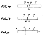
- Fig. 1(a) ceramic bodies 1A and 1B for use in a four point bending strength test with a predetermined shape and dimensions were prepared.
- Solution 10 containing a bonding aid was then applied on the machined surface 2A and/or 2B. In the example shown in Fig. 1(a), the solution 10 was applied on both machined surface 2A and 2B.
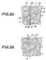
- Fig. 2(a) is an enlarged cross sectional view schematically showing a region near a bonding interface at that stage. That is, the microstructure of each ceramic body 1A and 1B is polycrystal structure, in which intergranular phases 11 are formed between ceramic particles or crystal particles 7. Ceramic particles 7A across the bonding interface are cut during the above machining process and cutting surfaces of the particles 7A expose on the machined surface 2A and 2B. When contacting the surfaces 2A and 2B, the cutting surfaces of the particles are contacted with each other with substantially no clearance by machining each surface 2A and 2B, as described above.
- the solution 10 is applied between the surfaces 2A and 2B to provide an assembly, which is then subjected to a heat treatment.
- the particles 7A contained in the ceramic body 1A and 1B were contacted and bonded with each other according to the diffusion of the bonding aid or agent in each particle 7A.
- the particles are bonded and grown as shown in Fig. 2(b) to form bonded particles 9, which grow across the bonding interface 4 and extend in the direction perpendicular to the interface 4.
- the invention provides a novel process that the cut particles 7A are contacted with substantially no clearance, bonded with each other and then grown across the bonding interface using the effect of the bonding aid, during the heat treatment. Consequently, for example, as shown in Fig. 3, a layer 12 rich in the bonding aid is formed along the bonding interface, and the bonded particles 9 occur and grow mainly in the layer 12 towards the direction perpendicular to the bonding interface. During that process, intergranular phases containing a great portion of the bonding aid is then dispersed as the growth of the bonded particles 9.
- the layer 12 may be clearly observed and confirmed by means of an electromicroscope.
- the cut particles 7A may not be bonded with each other, probably because a small clearance occurs between the contacted particles 7A.
- the particles 7A may not be bonded with each other, probably because the machined surfaces are contacted with each other leaving some clearance.
- the average surface roughness (Ra) is calculated as follows. A cross-sectional surface curve is measured and a center line of the curve is drawn. Thus, a sum of areas of regions encompassed by the curve and the center line is divided by a length "L" of the center line to provide the roughness.
- the flatness is a deviation of the surface interface from an ideal or geometrical interface. JIS defines the flatness as a distance of two geometrical interface which are parallel to each other, when the surface interface is sandwiched with the geometrical interfaces and the geometrical interfaces are placed so that the distance is made minimum.
- the surface roughness and the flatness may be measured with a device for measuring a surface roughness and a laser interferometer.
- the average surface roughness of the machined surface may preferably be not more than 0.1 ⁇ m and the flatness may preferably be not more than 0.1 ⁇ m. These values may preferably be as small as possible for forming the bonding with a higher strength and gas-tight performance and thus the definition of the minimum values is not needed. However, because of the upper limit of the accuracy of machining process of ceramics at the time the application was filed, the lower limit of the roughness was 0.05 ⁇ m and that of the flatness was 0.07 ⁇ m.
- the surface of the ceramic body may preferably be machined with a surface grinder and a lapping machine for producing the surface with the flatness and the surface roughness of the above predetermined values.
- Each ceramic body may preferably be subjected to the heat treatment at a temperature not lower than that at which the ceramic particles in the body start to grow, for growing the ceramic particles across the bonding interface towards the perpendicular direction to the interface.
- Such growth of the particles may occurs to some extent at a relatively low temperature.
- a sintering temperature of the ceramic body is taken as "T”
- the inventors confirmed that the thus produced bonded body has a strength comparable with a strength of a sintered body of the substantially same material and dimensions.
- the strength of the bonded body may be made maximum.
- the temperature of the treatment is higher than the sintering temperature, during the particle growth along the bonding interface is sufficiently progressed, extraordinary particle growth may occur in the sintered body itself at the same time. Such extraordinary particle growth may cause defects, which may degrade the strength of the sintered body itself.
- the sintering temperature of the ceramic body is taken as "T”
- the temperature of the heat treatment may preferably be not higher than "T+50"°C.
- the bonding aid may preferably be a sintering aid or agent applicable to the sintering process of the ceramic body, and more preferably be same as the sintering aid actually used.
- the bonding aid may preferably be one or more compound selected from the group consisting of a compound containing yttrium and a compound containing ytterbium, and most preferably be a compound containing yttrium.
- the following aids may preferably be used : aqueous solution of yttrium chloride, yttrium chloride hydrate, yttrium sulfate, or yttrium acetate; ethyl alcohol solution of yttrium chloride, yttrium chloride hydrate, or yttrium acetate.
- the bonding aid may preferably be one or more compound selected from the group consisting of a compound containing yttrium and a compound containing ytterbium, and most preferably be a compound containing yttrium.
- the ceramic bodies may be strongly bonded without applying a load on the bodies to be bonded.
- the load may be applied.
- An actual process for carrying out the heat treatment may be a heat treatment at an ambient pressure, a hot press process, a plasma activating process, a selective heating process using laser etc.
- a time period of the heat treatment may be varied depending on the size of the ceramic body or the temperature of the heat treatment.
- Samples each having a weight of 53 grams and sizes of 20 mm ⁇ 40 mm ⁇ 20mm were prepared as ceramic body samples.
- the samples were made of aluminum nitride.
- the samples were sintered at 1900°C. Additionally, a four point bending strength at a room temperature of each sample was about 400 MPa.
- the defects were not found and the four point bending strengths were considerably improved.
- the bending strength was made 400 MPa, which was substantially same as that of the used sample.
- the bonded article did not fractured along the bonding interface.
- a room temperature strength of 330 MPa and a high temperature strength of 300 MPa were attained.
- the fracture occurred along the bonding interface.
- the four point bending strength was improved.
- the bonded article fractured along the interface other than the bonding interface and the strength was slightly smaller than that of the sintered sample, probably because of the growth of the ceramic particles in the sample itself.
- the temperature of the heat treatment was 1800°C and too small for the bonding.
- the article was separated along the bonding interface and thus "-" was indicated in the column of "four point bending strength" in the Table.
- the condition of the bonding interface was good and a strength of 100 MPa was attained.
- the room temperature strength of the article was degraded than those in the experiment A1 to A3 and the four point bending strength at 600°C may not be measured.
- a powder diffusion process was carried out and the samples were not be bonded.
- the defects were not found along the bonding interface and the four point bending strength was excellent.
- the strength at a room temperature was 400 MPa, which is substantially same as that of the original samples, and the high temperature strength at 600°C was degraded by only 5 % comparing to that of the sample.
- the bonded article was not fractured along the bonding interface.
- a room temperature strength of 330 MPa and a high temperature strength of 300 MPa were attained.
- the temperature of the heat treatment was 1700°C and inadequate for producing the bonding. Moreover, when the thus produced article was subjected to the subsequent machining process, the article was separated. In the experiment B5, the temperature of the heat treatment was too high and especially in the sample made of silicon nitride, ingredients of the sample were vaporized to degrade the sample. In the experiment B6, the powder diffusion process was carried out. However, the assembly was heat treated at a high temperature of 1900°C and the samples were not be bonded.
- the defects were not found along the bonding interface and the four point bending strength was considerably high.
- the strength at a room temperature was 900 MPa, which is substantially same as that of the original sample, and the high temperature strength at 600°C was 870 MPa.
- the bonded article was not fractured along the bonding interface.
- a strength of 850 MPa was attained, however, the article was fractured along the bonding interface.
- a strength of 870 MPa was also attained and the degradation of the high temperature strength was hardly observed.
- the temperature of the heat treatment was 1700°C and inadequate for producing the bonding.
- the condition of the bonding was good and a strength of 300 MPa was attained.
- sintering of the sample made of silicon nitride was progressed and the strength itself was lowered comparing to those of the experiments C1 to C3.
- the powder diffusion process was carried out and the samples were not bonded when the assembly was heat treated at 1850°C.
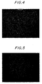
- Fig. 4 is a photograph of the ceramic microstructure taken as an image of secondary electrons by an electron microscope. The bonding interface exists in the central region of the photograph, however, such interface was not observable from the photograph.
- Fig. 5 is a photograph of this ceramic micro-structure taken as an image of back scattered electrons by an electron microscope. Yttrium atoms were observed as white dots. The bonding interface or interface exists in the central region of the photograph and a white line was observed along the bonding interface. Such white line is considered as follows: The bonding aid was applied on the machined surface of each sample and after the heat treatment, the bonding aid was left along the bonding interface. Yttrium atoms in the bonding aid were considered to be shown as the white line.
- Fig. 6 is a photograph of the enlarged view of the ceramic microstructure of figure 5, which is taken as an image of the back scattered electrons by an electron microscope.
- Fig. 7 is a photograph of the enlarged view of the ceramic microstructure near the bonding interface shown in figure 6, which is taken as an image of the back scattered electrons.
- the microstructure shown in figures 5 to 7, especially shown in figure 7, consists of particles made of aluminum nitride and grain boundary containing yttrium.
- yttrium atoms were indicated as white dots.
- Metal elements other than yttrium hardly exist in the grain boundary.
- Particles colored with dark brown indicate particles of aluminum nitride.
- Black portions were found between the aluminum nitride particles. Such portions indicates open pores.
- Fig. 3 schematically shows the central region of lower left portion of the photograph in figure 7. As shown in figures 3 and 7, the intergranular phases containing the bonding aid is moved and dispersed as the growth of the particles across the bonding interface.
- the bonded article and the process according to the invention may be applied to a system for preventing the leakage of a corrosive gas or a gas for producing semiconductors. Especially, they may be applied for an apparatus exposed to a corrosive gas or a gas for producing semiconductors.
- one ceramic body mat be a heating device comprising a metal member therein, heated by applying electric power
- the other ceramic body may be a tube shaped body bonded to the heating device, and the metal member exposed to an inner space of the tube shaped body.
- each ceramic body may preferably be made of aluminum nitride so that corrosion resistivity, especially for the halogen corrosive gas, of the heating device and the tube shaped body was considerably improved.
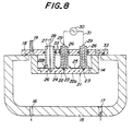
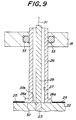
- Fig. 8 is a cross sectional view schematically showing the heating device installed in an apparatus for producing semiconductors and Fig. 9 is an enlarged view of the main portion of Fig. 8.
- a case 14 is installed in a chamber 15 of an apparatus for producing semiconductors and a disk shaped ceramic heater 21 for heating the semiconductors is held by the case 14.
- a heating surface 22 of the heater 21 has a size large enough for setting a semiconductor wafer thereon.
- a corrosive gas or a gas for producing semiconductor films is supplied from a gas supplying hole 17 into the inner space of the chamber 15. Air in the inner space is discharged from a discharge hole 16 by means of a vacuum pump.
- a heat resistor 24 is embedded within a disk shaped ceramic base 22 made of a densified and gas-tight material.
- a pair of bulk terminals 23 is embedded on a back side surface 22 b of the base 22 and the bulk terminals 23 are electrically connected to the heat resistor 24.
- One end of rod shaped electric suppliers 29 are electrically and mechanically connected to the bulk terminals 23, respectively.
- a lead wire 31 is electrically connected to another end of each electric supplier 29 and each lead wire 31 is connected to an alternating current electric supply 30. Electric power is supplied through each rod shaped supplier 29 to the heat resistor 24 to heat the ceramic heater 21 to a high temperature, such as maximum 1100°C.
- An upper side of the case 14 is covered by a flange 18 with a water cooling jacket 19, and the flange 18 and the wall of the chamber 15 are gas-tight sealed by means of an O-shaped ring 33.
- the flange 18 constitute the upper side wall of the chamber 15.
- An edge portion of a thermocouple 28 with a sheath made of stainless steel is connected to the base 22.
- a flange portion 26a is formed in the bottom portion of the tube shaped body 26 and bonded with the back side surface 22b of the heater. Therefore, the tube shaped body is bonded with the ceramic base 22 and unified.
- three circular holes are formed in the flange portion 18 and each tube shaped body 26 is inserted through each circular hole. An upper side of the tube shaped body 26 is exposed to the atmosphere outside of the chamber, therefore, each inner space of each tube shaped body 26 is filled with the atmosphere.
- the bottom portion of each tube shaped body 26 and the ceramic base 22 are gas-tight sealed.
- the tube shaped body 26 and the flange 18 are gas-tight sealed by the O-shaped ring 33 and electrically insulated.
- Each electric supplier 29 is connected to the bulk terminal 23.
- the electric supplier 26 is fixed in the inner space of the tube shaped body 26.
- the thermocouple 28 is used as a device for measuring a temperature and the thermocouple 28 is fixed in the inner space of the tube shaped body 26. Therefore, a pair of the electric suppliers 29, a pair of the bulk terminals 23, and the thermocouple 28 are exposed to the atmosphere outside of the chamber.
- the heating apparatus when a conductive film 25 is formed on the back side surface 22b by deposition, the thus formed deposition film 25 and the electric supplier 29 are electrically insulated by each tube shaped body 26. Therefore, it is possible to avoid the short circuit between the suppliers 29. Moreover, discharge or leak may be prevented between each electric supplier 29 and the chamber 15. Additionally, the electric suppliers 29 were not exposed to the inner space of the chamber, so that the corrosion of the suppliers 29 and the bulk terminals 23 and the contamination thereof may be prevented.
- thermocouple the behaviour of g as molecules around the thermocouple is within the range of viscous flow from an atmospheric pressure to the vacuum condition of 133 Pa (1 torr.) As the pressure is further lowered, the condition is converted to a range of molecular flow. Consequently, the condition of thermal transition around the thermocouple was considerably changed and accurate measurement of the temperatures by the thermocouple is made difficult. Moreover, in the viscous flow condition, when the pressure change is relatively large, existence of a deviation of the measured temperature is confirmed.
- the bonding region of the thermocouple 28 as the detector of the temperature and the base 22 are exposed to the atmosphere outside of the chamber, whose pressure does not changed during the process for forming the semi-conductor films. Therefore, the deviations according to the above change of the pressure may be prevented.
- each tube shaped body and each base may preferably be made of silicon nitride or aluminum nitride.
- the heating apparatus may be produce by bonding each tube shaped body 26 and the base 22.That is, the ceramic heater 21 is produced by an ambient pressure sintering process or a hot press process. Prior to the processes, the bulk terminals 23 and the heat resistor 24 are embedded within a ceramic shaped body. Additionally, a cylindrical shaped body is produced by an injection molding process, an extrusion process, a press molding process or a hydrostatic pressing process, and then sintered at an atmospheric pressure to produce the tube shaped body 26. According to the invention, the tube shaped body 26 may be bonded to a predetermined position of the disk shaped ceramic base 22 maintaining the gas-tight performance.
- the invention may be applied for producing the other type of heating apparatus as described below.
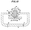
- the heating apparatus will be explained referring to Fig. 10.
- Fig. 10 the members already shown in Fig. 8 are indicated using the same numerals and the explanation will be omitted.
- the heat resistor 24 is embedded in a disk shaped base 37 and a wafer is set on a heating surface 37a.
- a tube shaped body 35 is bonded to a back side surface 37b of a base 37 maintaining gas-tight performance.
- the tube shaped body 35 and the chamber 15 are gas-tight sealed through the O-shaped ring 33.
- a flange portion 35a is formed in the end portion of the tube shaped body 35 and a flange surface 32 of the flange portion 35a is bonded to the back side surface 37b.
- One end of the electric supplier 29 is connected to the terminal and one end of the thermo-couple 28 is bonded to the ceramic base 37.
- the electric suppliers 29, the thermocouple 28 and the terminals 23 are exposed to the outer space 27 of the chamber.
- the tube shaped body 35 and the base 37 may preferably be made of silicon nitride and/or aluminum nitride as described above.
- the process of the invention may be applied.
- the heating apparatuses as shown in Fig. 8 and Fig. 9 are produced according to the above process.
- a wire made of molybdenum was used as the heat resistor 24 and it was produced the heater 21 made of aluminum nitride with a diameter of 235 mm by hot pressing at 1900°C.
- the tube shaped body 26 made of aluminum nitride with an outer diameter of 60 mm, an inner diameter of 50 mm and a length of 20 mm by pressureless sintering at 1900°C.
- Each surface to be bonded of the tube shaped body 26 and the base is machined by means of a surface grinder and a high speed lapping machine to produce the machined surface with an average surface roughness of 0.1 ⁇ m and a flatness of 0.1 ⁇ m.
- Aqueous solution of yttrium nitrate hydrate containing 2.61 ⁇ 10 -4 mol/cc of yttrium was applied on each machined surface to provide an assembly, which was then subjected to a heat treatment at 1900°C.
- the tube shaped body and the base were held and fixed in predetermined positions by a fixer so that the positions of them did not largely changed during the treatment.
- pressure or a load was not applied and their own loads were applied. Nitrogen gas was introduced as atmosphere during the heat treatment.
- the tube shaped body 26 and the base 22 were strongly bonded and not separated. Moreover, a resistance of the heat resistor was increased by not more than about 20 % during the treatment, which was practically admissible. Additionally, the thus produced heating apparatus was subjected to 400 heating cycles repeatedly. One heating cycle consists of one heating stage from a room temperature to 800°C and one cooling stage from 800°C to a room temperature. After the heating cycles were over, the resistance was increased by not more than 20 %. Moreover, gas leakage from the bonding interface did not occur.
- the heater 21 was not bonded or subjected to the heat treatment, and subjected to the 400 heat cycles as described above. After the heating cycles were over, the resistance was increased by not more than 20 %. As can be seen from the results, the heat treatment according to the invention did not substantially affect the property of the heat resistor.
- a novel process for bonding ceramic bodies may be provided. Additionally, when bonding the ceramic bodies to produce a bonded article, a mechanical strength of the bonded article may be improved to a value higher than that of the bonded article produced by prior processes. Moreover, a mechanical strength at the bonding interface may be improved to a value comparable with or even higher than that at an interface other than the bonding interface.
Landscapes
- Chemical & Material Sciences (AREA)
- Engineering & Computer Science (AREA)
- Ceramic Engineering (AREA)
- Materials Engineering (AREA)
- Structural Engineering (AREA)
- Organic Chemistry (AREA)
- Ceramic Products (AREA)
Claims (15)
- Verbundener Gegenstand, der einen ersten und einen zweiten Keramikkörper aufweist, wobei jeder Keramikkörper Keramikteilchen umfasst, die in einer intergranularen Phase vorliegen, wobei die Keramikkörper entlang jeweiliger Oberflächen miteinander verbunden sind, um eine Verbindungsgrenzfläche zu bilden, worin sich Keramikteilchen der Keramikkörper durch Festphasensintern entlang der Verbindungsgrenzfläche verbunden haben und gewachsen sind, so dass sie sich über die Verbindungsgrenzfläche hinaus und in sowohl den ersten als auch den zweiten Keramikkörper erstrecken, und worin Verbindungshilfsmaterial in der intergranularen Phase enthalten ist, so dass die Konzentration von Elementen des Verbindungshilfsmaterials in einer Schicht, die in den Keramikkörpern entlang der Verbindungsgrenzfläche liegt, höher ist als in jeweiligen Bereichen der Keramikkörper, die von der Verbindungsgrenzfläche weiter entfernt sind, wobei das Verbindungshilfsmaterial zwischen den Oberflächen der Keramikkörper aufgetragen worden ist.
- Verbundener Gegenstand nach Anspruch 1, worin der verbundene Gegenstand entlang einer Grenzfläche bricht, die nicht die Verbindungsgrenzfläche ist, wenn der verbundene Gegenstand einem Zugbruchtest unterzogen wird.
- Verbundener Gegenstand nach Anspruch 1 oder 2, worin die Verbindungshilfe eine Sinterhilfe ist, die sich zur Unterstützung des Sinterns in zumindest einem der Keramikkörper eignet.
- Verbundener Gegenstand nach Anspruch 3, worin die Verbindungshilfe eine Sinterhilfe ist, die in zumindest einem gesamten Keramikkörper vorhanden ist.
- Verbundener Gegenstand nach einem der Ansprüche 1 bis 4, worin die Keramikteilchen aus Aluminiumnitrid und/oder Siliziumnitrid bestehen und die Verbindungshilfe eine Yttrium enthaltende Substanz und/oder eine Ytterbium enthaltende Substanz ist.
- Verbundener Gegenstand nach einem der Ansprüche 1 bis 5, worin der verbundene Gegenstand eine Heizanlage ist, die einem oder mehreren Gasen, ausgewählt aus einem korrodierenden Gas und einem filmbildenden Gas, auszusetzen ist, wobei einer der Keramikkörper eine Heizvorrichtung ist, in der ein Metallelement enthalten ist, wobei das Metallelement durch das Anlegen von elektrischem Strom zu erhitzen ist, wobei der andere der Keramikkörper ein rohrförmiger Körper ist, und der rohrförmige Körper so mit der Heizvorrichtung verbunden ist, dass das Metallelement gegenüber einem Innenraum des rohrförmigen Körpers freiliegt.
- Verfahren zur Herstellung eines verbundenen Gegenstandes, der einen ersten und einen zweiten Keramikkörper aufweist, wobei jeder Keramikkörper Keramikteilchen umfasst, die in einer intergranularen Phase vorliegen, wobei die Keramikkörper entlang jeweiliger Oberflächen miteinander verbunden sind, so dass eine Verbindungsgrenzfläche gebildet wird, worin sich Keramikteilchen der Keramikkörper entlang der Verbindungsgrenzfläche durch Festphasensintern verbunden haben und gewachsen sind, so dass sie sich über die Verbindungsgrenzfläche hinaus und sowohl in den ersten als auch in den zweiten Keramikkörper erstrecken, und worin Verbindungshilfsmaterial in der intergranularen Phase enthalten ist, so dass die Konzentration von Elementen des Verbindungshilfsmaterials in einer Schicht, die in den Keramikkörpern entlang der Verbindungsgrenzfläche liegt, höher ist als in jeweiligen Bereichen der Keramikkörper, die von der Verbindungsgrenzfläche weiter entfernt sind, wobei das Verbindungshilfsmaterial zwischen den Oberflächen der Keramikkörper aufgetragen worden ist,
wobei das Verfahren folgende Schritte umfasst:das maschinelle Bearbeiten beider Keramikkörper, um die jeweiligen Oberflächen mit durchschnittlichen Oberflächenrauhigkeiten (Ra) von nicht mehr als 0,2 µm und Ebenheiten von nicht mehr 0,2 µm auszubilden;das Aufbringen einer Lösung der Verbindungshilfe auf zumindest eine der Oberflächen;das In-Kontakt-Bringen der Oberflächen miteinander, um eine Anordnung zu bilden; unddas Unterziehen der Anordnung einer Wärmebehandlung, um den verbundenen Gegenstand herzustellen. - Verfahren zur erstellung eines verbundenen Gegenstandes nach Anspruch 7, worin die Keramikkörper maschinell bearbeitet werden, um die jeweiligen Oberflächen mit durchschnittlichen Oberflächen-Rauhigkeiten (Ra) von nicht mehr als 0,1 µm und Ebenheiten von nicht mehr als 0,1 µm auszubilden.
- Verfahren zur Herstellung eines verbundenen Gegenstandes nach Anspruch 7 oder 8, worin die Anordnung der Wärmebehandlung bei einer Temperatur unterzogen wird, die nicht unter jener Temperatur liegt, bei der Keramikteilchen so in jedem der Keramikkörper wachsen können, dass die Keramikteilchen über die Verbindungsgrenzfläche der Keramikkörper hinaus wachsen.
- Verfahren zur Herstellung eines verbundenen Gegenstandes nach Anspruch 9, worin die Anordnung der Wärmebehandlung bei einer Temperatur von nicht unter (T - 50 °C) unterzogen wird, wobei die Sintertemperatur eines der Keramikkörper mit T °C angenommen wird.
- Verfahren zur Herstellung eines verbundenen Gegenstandes nach Anspruch 10, worin die Anordnung der Wärmebehandlung bei einer Temperatur von nicht über (T + 50 °C) unterzogen wird, wobei die Sintertemperatur eines der Keramikkörper mit T °C angenommen wird.
- Verfahren zur Herstellung eines verbundenen Gegenstandes nach Anspruch 11, worin die Anordnung der Wärmebehandlung bei einer Temperatur von nicht über der Sintertemperatur unterzogen wird.
- Verfahren zur Herstellung eines verbundenen Gegenstandes nach einem der Ansprüche 7 bis 12, worin die Verbindungshilfe eine Sinterhilfe ist, die dazu geeignet ist, das Sintern in zumindest einem der Keramikkörper zu unterstützen.
- Verfahren zur Herstellung eines verbundenen Gegenstandes nach Anspruch 13, worin die Keramikteilchen aus Aluminiumnitrid und/oder Siliziumnitrid bestehen und die Verbindungshilfe eine Yttrium enthaltende Substanz und/oder eine Ytterbium enthaltenden Substanz ist.
- Verfahren zur Herstellung eines verbundenen Gegenstandes nach einem der Ansprüche 8 bis 14, worin die Verbindungshilfe Y(NO3)3·6H2O ist und als wässrige Lösung aufgebracht wird.
Applications Claiming Priority (3)
| Application Number | Priority Date | Filing Date | Title |
|---|---|---|---|
| JP23021394 | 1994-09-01 | ||
| JP6230213A JP2783980B2 (ja) | 1994-09-01 | 1994-09-01 | 接合体およびその製造方法 |
| JP230213/94 | 1994-09-01 |
Publications (3)
| Publication Number | Publication Date |
|---|---|
| EP0699643A2 EP0699643A2 (de) | 1996-03-06 |
| EP0699643A3 EP0699643A3 (de) | 1996-09-25 |
| EP0699643B1 true EP0699643B1 (de) | 2000-05-10 |
Family
ID=16904343
Family Applications (1)
| Application Number | Title | Priority Date | Filing Date |
|---|---|---|---|
| EP95304726A Expired - Lifetime EP0699643B1 (de) | 1994-09-01 | 1995-07-06 | Verbundene Gegenstände und Verfahren zur Herstellung derselben |
Country Status (5)
| Country | Link |
|---|---|
| US (2) | US5721062A (de) |
| EP (1) | EP0699643B1 (de) |
| JP (1) | JP2783980B2 (de) |
| KR (1) | KR0148432B1 (de) |
| DE (1) | DE69516772T2 (de) |
Families Citing this family (30)
| Publication number | Priority date | Publication date | Assignee | Title |
|---|---|---|---|---|
| JP2783980B2 (ja) * | 1994-09-01 | 1998-08-06 | 日本碍子株式会社 | 接合体およびその製造方法 |
| JP3891908B2 (ja) * | 1995-07-19 | 2007-03-14 | 株式会社トクヤマ | 窒化アルミニウム接合構造体の製造方法 |
| JP3891621B2 (ja) * | 1996-12-19 | 2007-03-14 | 株式会社トクヤマ | 窒化アルミニウム部材 |
| JP3604888B2 (ja) * | 1997-01-30 | 2004-12-22 | 日本碍子株式会社 | 窒化アルミニウム質セラミックス基材の接合体、窒化アルミニウム質セラミックス基材の接合体の製造方法及び接合剤 |
| US6494955B1 (en) | 2000-02-15 | 2002-12-17 | Applied Materials, Inc. | Ceramic substrate support |
| JP2001244902A (ja) * | 2000-02-29 | 2001-09-07 | Sony Corp | 送信装置および方法、受信装置および方法、並びに記録媒体 |
| US6997993B2 (en) | 2001-02-09 | 2006-02-14 | Ngk Insulators, Ltd. | Susceptor supporting construction |
| US20040094871A1 (en) * | 2001-04-12 | 2004-05-20 | Yasutaka Ito | Ceramic bonded body and its producing method, and ceramic structure for semiconductor wafer |
| KR20040030803A (ko) * | 2001-07-19 | 2004-04-09 | 이비덴 가부시키가이샤 | 세라믹 접합체 및 그 접합방법, 세라믹 구조체 |
| EP1422754A1 (de) | 2001-08-10 | 2004-05-26 | Ibiden Co., Ltd. | Keramischer verbindungskörper |
| US20050156322A1 (en) * | 2001-08-31 | 2005-07-21 | Smith Lee J. | Thin semiconductor package including stacked dies |
| US6730175B2 (en) | 2002-01-22 | 2004-05-04 | Applied Materials, Inc. | Ceramic substrate support |
| JP2004253665A (ja) * | 2003-02-21 | 2004-09-09 | Sumitomo Electric Ind Ltd | 半導体製造装置用ウェハ保持体およびそれを搭載した半導体製造装置 |
| EP1642876A4 (de) | 2003-06-13 | 2011-01-05 | Tokuyama Corp | Aluminiumnitrid-konjugatkörper und herstellungsverfahren dafür |
| JP4787568B2 (ja) | 2004-11-16 | 2011-10-05 | 日本碍子株式会社 | 接合剤、窒化アルミニウム接合体及びその製造方法 |
| TW200633947A (en) | 2005-02-16 | 2006-10-01 | Ngk Insulators Ltd | Joined body and manufacturing method for the same |
| JP4921150B2 (ja) * | 2005-12-27 | 2012-04-25 | 日本碍子株式会社 | 窒化アルミニウム接合体の製造方法 |
| JP5336176B2 (ja) | 2006-03-29 | 2013-11-06 | 株式会社トクヤマ | 窒化アルミニウム焼結体の接合方法および窒化アルミニウム接合体 |
| US20090277388A1 (en) * | 2008-05-09 | 2009-11-12 | Applied Materials, Inc. | Heater with detachable shaft |
| DE102008036835A1 (de) * | 2008-08-07 | 2010-02-18 | Epcos Ag | Heizungsvorrichtung und Verfahren zur Herstellung der Heizungsvorrichtung |
| DE102008036836A1 (de) * | 2008-08-07 | 2010-02-11 | Epcos Ag | Formkörper, Heizungsvorrichtung und Verfahren zur Herstellung eines Formkörpers |
| US8580593B2 (en) * | 2009-09-10 | 2013-11-12 | Micron Technology, Inc. | Epitaxial formation structures and associated methods of manufacturing solid state lighting devices |
| WO2012056808A1 (ja) | 2010-10-25 | 2012-05-03 | 日本碍子株式会社 | セラミックス材料、半導体製造装置用部材、スパッタリングターゲット部材及びセラミックス材料の製造方法 |
| WO2012056807A1 (ja) | 2010-10-25 | 2012-05-03 | 日本碍子株式会社 | セラミックス材料、積層体、半導体製造装置用部材及びスパッタリングターゲット部材 |
| JP6078450B2 (ja) | 2012-10-26 | 2017-02-08 | 日本碍子株式会社 | 半導体製造装置用部材及びその製法 |
| KR102276101B1 (ko) | 2013-12-27 | 2021-07-13 | 엔지케이 인슐레이터 엘티디 | 접합재 조성물, 질화알루미늄 접합체 및 그 제법 |
| JP6370062B2 (ja) * | 2014-02-28 | 2018-08-08 | 日本特殊陶業株式会社 | 窒化アルミニウム接合体およびその製造方法 |
| CN110959306B (zh) | 2018-07-13 | 2022-02-11 | 日本碍子株式会社 | 陶瓷加热器 |
| JP6959201B2 (ja) | 2018-08-29 | 2021-11-02 | 日本碍子株式会社 | セラミックヒータ |
| WO2025047709A1 (ja) * | 2023-08-30 | 2025-03-06 | ボンドテック株式会社 | 静電チャック製造方法および静電チャック |
Family Cites Families (8)
| Publication number | Priority date | Publication date | Assignee | Title |
|---|---|---|---|---|
| JPS4920370B1 (de) * | 1970-12-28 | 1974-05-24 | ||
| JPS6026076B2 (ja) * | 1979-05-31 | 1985-06-21 | 日本碍子株式会社 | セラミツクス物品の接合方法 |
| US4960736A (en) * | 1986-09-16 | 1990-10-02 | Lanxide Technology Company, Lp | Surface bonding of ceramic bodies |
| US5240171A (en) * | 1987-05-21 | 1993-08-31 | Lanxide Technology Company, Lp | Method for surface bonding of ceramic bodies |
| JP2823626B2 (ja) * | 1990-01-19 | 1998-11-11 | 信越化学工業株式会社 | Mn―Znフェライト接合体の製造方法 |
| US5306895A (en) * | 1991-03-26 | 1994-04-26 | Ngk Insulators, Ltd. | Corrosion-resistant member for chemical apparatus using halogen series corrosive gas |
| JP2677921B2 (ja) * | 1991-03-26 | 1997-11-17 | 日本碍子株式会社 | 半導体設置用装置 |
| JP2783980B2 (ja) * | 1994-09-01 | 1998-08-06 | 日本碍子株式会社 | 接合体およびその製造方法 |
-
1994
- 1994-09-01 JP JP6230213A patent/JP2783980B2/ja not_active Expired - Lifetime
-
1995
- 1995-06-07 US US08/487,690 patent/US5721062A/en not_active Expired - Lifetime
- 1995-07-06 DE DE69516772T patent/DE69516772T2/de not_active Expired - Lifetime
- 1995-07-06 EP EP95304726A patent/EP0699643B1/de not_active Expired - Lifetime
- 1995-07-26 KR KR1019950022341A patent/KR0148432B1/ko not_active Expired - Lifetime
-
1997
- 1997-10-24 US US08/957,067 patent/US6071465A/en not_active Expired - Lifetime
Non-Patent Citations (1)
| Title |
|---|
| WORLD PATENTS INDEX, abstract no. 74-46090V * |
Also Published As
| Publication number | Publication date |
|---|---|
| EP0699643A2 (de) | 1996-03-06 |
| US5721062A (en) | 1998-02-24 |
| US6071465A (en) | 2000-06-06 |
| DE69516772D1 (de) | 2000-06-15 |
| EP0699643A3 (de) | 1996-09-25 |
| KR960010589A (ko) | 1996-04-20 |
| KR0148432B1 (ko) | 1998-11-16 |
| DE69516772T2 (de) | 2001-04-05 |
| JPH0873280A (ja) | 1996-03-19 |
| JP2783980B2 (ja) | 1998-08-06 |
Similar Documents
| Publication | Publication Date | Title |
|---|---|---|
| EP0699643B1 (de) | Verbundene Gegenstände und Verfahren zur Herstellung derselben | |
| US5231690A (en) | Wafer heaters for use in semiconductor-producing apparatus and heating units using such wafer heaters | |
| US8475613B2 (en) | Bonding agent, aluminum nitride composite body, and manufacturing method of the same | |
| EP1602635A1 (de) | Verfahren zur Herstellung einer Sinterkörper mit einem vergrabene Metallelement | |
| US7211153B2 (en) | Ceramic joined body, substrate holding structure and substrate processing apparatus | |
| JP3512650B2 (ja) | 加熱装置 | |
| TWI413438B (zh) | 半導體製造裝置用之保持單元、及裝載有該保持單元之半導體製造裝置 | |
| WO2006057408A1 (ja) | 複合セラミック体とその製造方法およびマイクロ化学チップ並びに改質器 | |
| JPH10242252A (ja) | ウエハ加熱装置 | |
| US20210305083A1 (en) | Stacked structure and semiconductor manufacturing apparatus member | |
| TW202032711A (zh) | 保持裝置及保持裝置的製造方法 | |
| JP5466439B2 (ja) | セラミックス接合体並びにセラミックスヒータ、静電チャック及びサセプタ | |
| US6063514A (en) | Gas-tight article and a producing process thereof | |
| JP7064987B2 (ja) | セラミックス接合体 | |
| EP1249858A2 (de) | Heizelement zur Montage eines Heizobjekts und Substratverarbeitungsvorrichtung dafür | |
| JP2003152064A (ja) | 電極内蔵型サセプタ及びその製造方法 | |
| US12154812B2 (en) | Electrostatic chuck | |
| JPH1053470A (ja) | セラミックス接合体およびその製造方法 | |
| JP2003224044A (ja) | 試料加熱装置及びその製造方法 | |
| EP4039659B1 (de) | Wärmereflektierendes element und verfahren zur herstellung eines glaselements, das eine wärmereflektierende schicht aufweist | |
| JP2677921B2 (ja) | 半導体設置用装置 | |
| US20230389134A1 (en) | Methods of making heating blocks, heating blocks, and semiconductor processing systems having heating blocks | |
| TWI655170B (zh) | 半導體製造裝置用零件 | |
| KR100403790B1 (ko) | 마그네슘을 이용한 세라믹과 금속의 접합방법 | |
| JP2021116216A (ja) | 半導体製造装置用部品 |
Legal Events
| Date | Code | Title | Description |
|---|---|---|---|
| PUAI | Public reference made under article 153(3) epc to a published international application that has entered the european phase |
Free format text: ORIGINAL CODE: 0009012 |
|
| AK | Designated contracting states |
Kind code of ref document: A2 Designated state(s): DE FR GB |
|
| PUAL | Search report despatched |
Free format text: ORIGINAL CODE: 0009013 |
|
| AK | Designated contracting states |
Kind code of ref document: A3 Designated state(s): DE FR GB |
|
| 17P | Request for examination filed |
Effective date: 19970319 |
|
| 17Q | First examination report despatched |
Effective date: 19970411 |
|
| GRAG | Despatch of communication of intention to grant |
Free format text: ORIGINAL CODE: EPIDOS AGRA |
|
| GRAG | Despatch of communication of intention to grant |
Free format text: ORIGINAL CODE: EPIDOS AGRA |
|
| GRAG | Despatch of communication of intention to grant |
Free format text: ORIGINAL CODE: EPIDOS AGRA |
|
| GRAH | Despatch of communication of intention to grant a patent |
Free format text: ORIGINAL CODE: EPIDOS IGRA |
|
| GRAH | Despatch of communication of intention to grant a patent |
Free format text: ORIGINAL CODE: EPIDOS IGRA |
|
| GRAA | (expected) grant |
Free format text: ORIGINAL CODE: 0009210 |
|
| AK | Designated contracting states |
Kind code of ref document: B1 Designated state(s): DE FR GB |
|
| REF | Corresponds to: |
Ref document number: 69516772 Country of ref document: DE Date of ref document: 20000615 |
|
| ET | Fr: translation filed | ||
| PLBE | No opposition filed within time limit |
Free format text: ORIGINAL CODE: 0009261 |
|
| STAA | Information on the status of an ep patent application or granted ep patent |
Free format text: STATUS: NO OPPOSITION FILED WITHIN TIME LIMIT |
|
| 26N | No opposition filed | ||
| REG | Reference to a national code |
Ref country code: GB Ref legal event code: IF02 |
|
| PGFP | Annual fee paid to national office [announced via postgrant information from national office to epo] |
Ref country code: DE Payment date: 20140702 Year of fee payment: 20 |
|
| PGFP | Annual fee paid to national office [announced via postgrant information from national office to epo] |
Ref country code: GB Payment date: 20140702 Year of fee payment: 20 Ref country code: FR Payment date: 20140708 Year of fee payment: 20 |
|
| REG | Reference to a national code |
Ref country code: DE Ref legal event code: R071 Ref document number: 69516772 Country of ref document: DE |
|
| REG | Reference to a national code |
Ref country code: GB Ref legal event code: PE20 Expiry date: 20150705 |
|
| PG25 | Lapsed in a contracting state [announced via postgrant information from national office to epo] |
Ref country code: GB Free format text: LAPSE BECAUSE OF EXPIRATION OF PROTECTION Effective date: 20150705 |