EP0699596B1 - Vorrichtung zur Ausgabe von flüssigen oder pastösen Produkten unter Druck, versehen mit einem Garantiebetätigungsknopf - Google Patents
Vorrichtung zur Ausgabe von flüssigen oder pastösen Produkten unter Druck, versehen mit einem Garantiebetätigungsknopf Download PDFInfo
- Publication number
- EP0699596B1 EP0699596B1 EP19950401707 EP95401707A EP0699596B1 EP 0699596 B1 EP0699596 B1 EP 0699596B1 EP 19950401707 EP19950401707 EP 19950401707 EP 95401707 A EP95401707 A EP 95401707A EP 0699596 B1 EP0699596 B1 EP 0699596B1
- Authority
- EP
- European Patent Office
- Prior art keywords
- push button
- ledge
- dispenser
- ring
- dispenser according
- Prior art date
- Legal status (The legal status is an assumption and is not a legal conclusion. Google has not performed a legal analysis and makes no representation as to the accuracy of the status listed.)
- Expired - Lifetime
Links
- 239000007788 liquid Substances 0.000 title claims description 13
- 210000002105 tongue Anatomy 0.000 claims description 15
- 230000000295 complement effect Effects 0.000 claims description 7
- 239000006260 foam Substances 0.000 claims description 6
- 230000002093 peripheral effect Effects 0.000 claims description 6
- 239000003380 propellant Substances 0.000 claims description 5
- 239000012263 liquid product Substances 0.000 claims description 4
- 239000000443 aerosol Substances 0.000 claims description 3
- 239000000047 product Substances 0.000 description 9
- 238000009826 distribution Methods 0.000 description 5
- 239000011324 bead Substances 0.000 description 4
- 238000004519 manufacturing process Methods 0.000 description 4
- 238000003825 pressing Methods 0.000 description 4
- 230000001681 protective effect Effects 0.000 description 3
- 239000007921 spray Substances 0.000 description 3
- 239000004744 fabric Substances 0.000 description 2
- 239000008267 milk Substances 0.000 description 2
- 210000004080 milk Anatomy 0.000 description 2
- 235000013336 milk Nutrition 0.000 description 2
- 238000005507 spraying Methods 0.000 description 2
- 230000000202 analgesic effect Effects 0.000 description 1
- 230000003110 anti-inflammatory effect Effects 0.000 description 1
- 239000002537 cosmetic Substances 0.000 description 1
- 238000002788 crimping Methods 0.000 description 1
- 239000002781 deodorant agent Substances 0.000 description 1
- 230000002951 depilatory effect Effects 0.000 description 1
- 239000008266 hair spray Substances 0.000 description 1
- 239000000077 insect repellent Substances 0.000 description 1
- 238000003780 insertion Methods 0.000 description 1
- 230000037431 insertion Effects 0.000 description 1
- 238000012423 maintenance Methods 0.000 description 1
- 230000003287 optical effect Effects 0.000 description 1
- 239000003973 paint Substances 0.000 description 1
- 230000011664 signaling Effects 0.000 description 1
- 230000000475 sunscreen effect Effects 0.000 description 1
- 239000000516 sunscreening agent Substances 0.000 description 1
Images

Classifications
-
- B—PERFORMING OPERATIONS; TRANSPORTING
- B65—CONVEYING; PACKING; STORING; HANDLING THIN OR FILAMENTARY MATERIAL
- B65D—CONTAINERS FOR STORAGE OR TRANSPORT OF ARTICLES OR MATERIALS, e.g. BAGS, BARRELS, BOTTLES, BOXES, CANS, CARTONS, CRATES, DRUMS, JARS, TANKS, HOPPERS, FORWARDING CONTAINERS; ACCESSORIES, CLOSURES, OR FITTINGS THEREFOR; PACKAGING ELEMENTS; PACKAGES
- B65D83/00—Containers or packages with special means for dispensing contents
- B65D83/14—Containers or packages with special means for dispensing contents for delivery of liquid or semi-liquid contents by internal gaseous pressure, i.e. aerosol containers comprising propellant for a product delivered by a propellant
- B65D83/16—Containers or packages with special means for dispensing contents for delivery of liquid or semi-liquid contents by internal gaseous pressure, i.e. aerosol containers comprising propellant for a product delivered by a propellant characterised by the actuating means
- B65D83/20—Containers or packages with special means for dispensing contents for delivery of liquid or semi-liquid contents by internal gaseous pressure, i.e. aerosol containers comprising propellant for a product delivered by a propellant characterised by the actuating means operated by manual action, e.g. button-type actuator or actuator caps
- B65D83/205—Actuator caps, or peripheral actuator skirts, attachable to the aerosol container
-
- B—PERFORMING OPERATIONS; TRANSPORTING
- B65—CONVEYING; PACKING; STORING; HANDLING THIN OR FILAMENTARY MATERIAL
- B65D—CONTAINERS FOR STORAGE OR TRANSPORT OF ARTICLES OR MATERIALS, e.g. BAGS, BARRELS, BOTTLES, BOXES, CANS, CARTONS, CRATES, DRUMS, JARS, TANKS, HOPPERS, FORWARDING CONTAINERS; ACCESSORIES, CLOSURES, OR FITTINGS THEREFOR; PACKAGING ELEMENTS; PACKAGES
- B65D83/00—Containers or packages with special means for dispensing contents
- B65D83/14—Containers or packages with special means for dispensing contents for delivery of liquid or semi-liquid contents by internal gaseous pressure, i.e. aerosol containers comprising propellant for a product delivered by a propellant
- B65D83/16—Containers or packages with special means for dispensing contents for delivery of liquid or semi-liquid contents by internal gaseous pressure, i.e. aerosol containers comprising propellant for a product delivered by a propellant characterised by the actuating means
- B65D83/22—Containers or packages with special means for dispensing contents for delivery of liquid or semi-liquid contents by internal gaseous pressure, i.e. aerosol containers comprising propellant for a product delivered by a propellant characterised by the actuating means with a mechanical means to disable actuation
- B65D83/224—Tamper indicating means obstructing initial actuation, e.g. removable
- B65D83/228—Tamper indicating means obstructing initial actuation, e.g. removable consisting of a rupturable connection between actuator element and actuator cap or skirt, e.g. tear strips or bridges
Definitions
- the invention relates to a dispenser according to the preamble of claim 1 for dispensing a product of more or less liquid consistency under the action of a propellant, this dispenser comprising a container forming a reservoir for the product.
- the dispenser according to the present invention can be used in various fields of use and serve for the distribution of cosmetic products (hairspray, deodorant, hair foam, body milk, depilatory foam, liquid foundation, sunscreen milk) or dermopharmaceuticals. (insect repellent, analgesic or anti-inflammatory), household products, paint, etc ... in the form of liquid, spray or foam.
- cosmetic products hairspray, deodorant, hair foam, body milk, depilatory foam, liquid foundation, sunscreen milk
- dermopharmaceuticals insect repellent, analgesic or anti-inflammatory
- household products paint, etc ... in the form of liquid, spray or foam.
- a distributor of pressurized liquid has been described by the applicant in document FR-A-2 661 661.
- This distributor comprises a reservoir equipped with a distribution valve provided with a control rod; the dispenser further comprises a push button comprising a pin capable of acting on the rod, a conduit passing through the pin and connecting the outlet of the rod to a nozzle provided in the push button, a retaining hoop capable of fix on the container, to maintain the push button. It allows the user to actuate the dispensing valve by exerting a reduced force on the push button, which gives this user a feeling of smooth operation during actuation.
- the support zone on the push button has a relatively large angular extent, which facilitates the use of this dispenser.
- the actuating device (hoop-push button) of this dispenser consists of two separate parts, which requires mounting, on a production line, relatively expensive and complex, from an industrial point of view.
- Another drawback of this dispenser lies in the fact that the valve which can be used for this dispenser can only be a so-called lateral deformation valve, which requires special industrial assembly tools. This results in a high cost price for the distributor.
- connection between the push button and the element fixed to the dispenser tank is broken by actuation of the push button.
- this actuation can at the same time control the dispensing of product.
- it is desirable that the connection can be broken independently of pressing the push button to avoid the simultaneous, involuntary, distribution of product.
- the present invention therefore aims to remedy the drawbacks mentioned above.
- the present invention aims, above all, to provide a distributor of the kind defined above whose manufacture and assembly are simpler than those of the distributor according to FR-A-2 661 661, the cost price of which is as low as possible, and the connection between the push button and the hoop being broken without dispensing product, while guaranteeing the user the state strictly new product by a non-violation system.
- the subject of the present invention is therefore the new industrial product that constitutes a distributor comprising a valve for dispensing a liquid product to be dispensed in the form of an aerosol or a foam using a propellant, this valve being mounted on a container containing the liquid and being provided with a control rod; a push button for actuating the valve, this push button comprising a pin capable of acting on the rod a nozzle provided in the push button a conduit passing through the pin and connecting the outlet of the rod to the nozzle a retaining band, able to be fixed on the container, for the maintenance of the push button, the push button (4) being molded in one piece with the retaining hoop (23) and a connection (18) being provided between the hoop (23) and the push button (4), characterized in that the connection is arranged so as to be broken only by rotation of the push button (4) relative to the hoop (23), when the dispenser is used for the first time, this link (18) constituting a non-violation device.
- connection between the hoop and the push button is established in the form of at least one thin tongue, extending in a direction parallel to an axis of symmetry of the dispenser.
- one or more tongues are used, for example 3 to 12 in number, preferably spaced regularly from one another.
- the tongues have first and second ends, the first end being fixed on a first sidewalk secured to a peripheral edge of the push button, the second end being fixed on a second complementary sidewalk, integral with an annular plate forming part of the hoop.
- first and second sidewalks are located, respectively, on either side of the tongue and are secured respectively to the push button and the hoop.
- This arrangement allows the hoop-link-push button assembly to be molded.
- the first sidewalk can be provided with a recess having a dimension equal to the length of the tongue, so that the latter can be accommodated in this recess after the rotation of the push button relative to the hoop.
- the first sidewalk has a support plate connected to this recess by a slope. This slope facilitates the rotation of the push button in its operating position.
- the second sidewalk preferably comprises a stop, a bearing surface capable of cooperating with the tray of the first sidewalk, a bead defining with the stopper a bearing surface for the tray of the first sidewalk after the rotation of the push button relative to the hoop, and possibly a slope, preferably with the same inclination and complementary orientation to that of the slope of the first sidewalk.
- Two optical violation indicators can be provided on the hoop and the push button respectively, indicating, by the position of one relative to the other, whether the dispenser has already been used or not.
- the hoop can also include a latching means for a protective cover.
- Figure 1 is a partial axial section of a distributor of pressurized liquid product, equipped with a non-violation device according to the invention.
- Figure 2 is a top view of the dispenser of Figure 1.
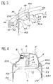
- FIG. 3 represents an enlarged perspective view of a non-violation tab, according to the invention, connecting the hoop and the push button of the dispenser of FIG. 1.
- Figure 4 shows a section similar to that of Figure 1, the dispenser being shown during spraying.
- a liquid distributor designated as a whole by the reference 1, equipped with a push button 4 to actuate a distribution valve 2 mounted on a reservoir 3, generally cylindrical and having an axis A of symmetry.
- the reservoir 3 contains a liquid product, under pressure using a propellant gas, this liquid having to be distributed in the form of an aerosol or a foam.
- the push button 4 in the form of a cap, has a peripheral edge 4a which comprises, along the axis A, a cylindrical pin 5 secured to the upper wall 4b of the push button 4.
- This wall 4b is slightly rounded.
- the pin 5 is crossed by an axial duct 6, which is connected to a transverse channel 7, leading to a spray nozzle 8, mounted, in a conventional manner, on a centering piece 9, provided in the push button 4 in a flat area 4c on a slope.
- the zone 4c has substantially, in front view, the shape of a trapezoid having a large base 40, two lateral sides 41, 42 and a small base 43 slightly curved outwards which is connected to the bearing surface 4b of the push button 4.
- connection zone 43 Apart from the connection zone 43, the surface 4b is delimited by a peripheral edge 44, widening towards a frustoconical portion 4d which constitutes the side wall of the push button 4.
- the frustoconical portion 4d is connected to a cylindrical skirt 4f which carries the peripheral edge 4a.
- the large base 40 of the trapezoidal area 4c is part of a segment 4e which connects the area 4c to a part of the skirt 4f.
- the free end (on the reservoir side) of the conduit 6 has a bore 10 of larger diameter than that of the conduit 6, so as to form a housing, capable of receiving, with a slight tightening, the free end of a rod 11 for controlling the valve 2.
- This valve is a conventional valve, the opening of which is controlled by pressing the rod 11 along the axis A.
- the valve 2 comprises a body 12 which is crimped, in the upper part, on the side of the control rod, in a cup 13, fixed by crimping or swaging on a circular opening made at the top of a dome 3a of the reservoir 3, comprising a rolled edge 14 and covering the upper end of a cylindrical portion 3b of the reservoir 3.
- the lower part of the valve body 12, located on the side opposite to the control rod 11, is provided with a connection zone 15, extended by a dip tube 16 extending to the bottom of the tank 3.
- the entire surface 4b of the upper wall of the push button 4, shown hatched in FIG. 2, constitutes a support zone, on which the user exerts pressure to control the opening of the valve 2.
- the push button 4 is connected by its peripheral edge 4a and via thin tabs 30 to an annular plate 23a of a retaining hoop 23 of generally shape cylindrical.
- the push button-tabs-hoop assembly is made in one piece.
- the hoop 23, at its end opposite the reservoir, is provided with an annular recess 23b intended for the snap-fastening of a protective cover 17, which the user removes before use.
- the end 23c of the hoop 23, located on the side facing the tank 3, has an internal snap-on bead 24, capable of snapping into an annular groove 3c of the tank, provided at the junction between the cylindrical part 3b of the tank 3 and its dome 3a.
- the annular plate 23a of the hoop 23 internally has eight notches or slots 35, separated by eight projections 36. Through each notch 35, we can see a first sidewalk 50, integral with the base 4a of the push button.
- FIG. 3 A detailed view of a notch 35 and a projection 36 is shown in FIG. 3. It can be seen that the sidewalks 50 are located opposite and below the notches 35. Each first sidewalk 50 has a support plate 52 and a recess 54 connected to the support plate 52 by a slope 53. On the opposite side to the plate 52, this recess 54 is delimited by a tongue 30 which is fixed to the sidewalk 50 by a first end 30a, and which has an axial orientation along the axis A of symmetry of the distributor.
- a second end 30b of each tongue 30 is fixed to a second sidewalk 60, integral with a projection 36.
- These second sidewalks 60 of orientation opposite to the first sidewalks 50, have a bearing surface 63 delimited by a stop 64 and by a bead 62.
- Each stop 62 is connected by a slope 61, of the same inclination and complementary orientation to that of the slope 53 of the first sidewalk 50 corresponding to the second end 30b of the associated tongue 30.
- this dispenser is as follows: when the user wishes to dispense liquid for the first time, he removes the protective cover 17, then he grasps the container 3 with one hand and the push button 4 with the other . Then, it rotates the push button relative to the container until the appearance of an audible click, signaling the rupture of the tongues 30.
- each tongue 30 lies down in the recess 54 of the first sidewalk 50 associated, and successively, the slopes 53, 61 of the first 50 and second sidewalks 60 complementary slide on each other.
- each first sidewalk 50 faces a second sidewalk 60, each first sidewalk being in abutment against the stop 64 and held by the bead 62 of the second complementary sidewalk 60. There are therefore, between the hoop 23 and the push button 4, pairs of sidewalks in support, successive.
- the distributor is operational.
- the user presses any point on the bearing surface 4b of the push button 4 to control the opening of the dispensing valve 2.
- a first determined sidewalk 50a moves away from the second sidewalk 60a, with which it was in contact before.
- the plate 52 of another first sidewalk 50b and the support surface 63 of another associated second sidewalk 60b remain in contact with each other under the action a return spring, which is provided with the distribution valve 2 the plate 52 of the sidewalk 50b and the surface 63 of the sidewalk 60b form a pivoting area.
- the depression of the push button causes, via the pin 5, the descent of the rod 11 in the direction of the valve, and causes the opening thereof.
- the liquid, under the thrust of the propellant gas rises, via the dip tube 16, in the body 12 of the valve, from where it will routed through the rod 11, the conduit 6 and the channel 7, to the spray nozzle 8.
- the push button is able to exert a leverage on the control rod. Consequently, the pressing force, necessary to trigger the spraying of the liquid, is reduced compared to a conventional dispenser, and the user will appreciate the smooth operation of this dispenser.
- the assembly (hoop-tabs-push button) is molded in a single step, which reduces the time and the manufacturing cost, and facilitates the mounting of the dispenser.
Landscapes
- Chemical & Material Sciences (AREA)
- Dispersion Chemistry (AREA)
- Engineering & Computer Science (AREA)
- Mechanical Engineering (AREA)
- Containers And Packaging Bodies Having A Special Means To Remove Contents (AREA)
Claims (9)
- Ausgabevorrichtung mit einer Ausgabedüse (2) eines auszugebenden flüssigen Produktes in Form eines Aerosols oder eines Schaums mit einem Treibgas, wobei das Ventil (2) auf einem Behälter (3) befestigt ist, der die Flüssigkeit enthält und wobei das Ventil mit einem Betätigungsschaft (11) versehen ist, mit einem Druckkopf (4) zum Betätigen des Ventils, wobei der Druckkopf (4) ein Organ (5) betätigt, welches auf den Schaft (11) einwirken kann, mit einer Düse (8), die im Druckkopf (4) vorgesehen ist, mit einem Kanal (6), der das Organ durchquert und den Ausgang des Schaftes (11) mit der Düse verbindet, mit einem Rückhaltering (23), der auf dem Behälter (3) befestigt werden kann, um den Druckkopf (4) zu befestigen, wobei der Druckkopf (4) einstückig mit dem Befestigungsring (23) und einer Verbindung (18) ausgeführt ist, die zwischen dem Ring (23) und dem Druckkopf (4) vorgesehen ist, dadurch gekennzeichnet, daß
die Verbindung so ausgeführt ist, daß sie nur durch Drehung des Druckkopfes (4) gegenüber dem Ring (23) während der ersten Benutzung der Ausgabevorrichtung gelöst werden kann, wobei diese Verbindung (18) eine Echtheitsgarantievorrichtung bildet. - Vorrichtung nach Anspruch 1,
dadurch gekennzeichnet, daß
die Verbindung (18), die zwischen dem Ring (23) und dem Druckkopf (4) vorgesehen ist, die Form mindestens einer schmalen Zunge (30) hat, die sich in einer Richtung parallel zur Symmetrieachse der Ausgabevorrichtung erstreckt. - Vorrichtung nach Anspruch 2,
dadurch gekennzeichnet, daß
die Zungen (30) mindestens drei bis zwölf an der Zahl sind. - Vorrichtung nach einem der Ansprüche 2 oder 3,
dadurch gekennzeichnet, daß
die Zunge (30) ein erstes und ein zweites Ende aufweist, das erste Ende (30a) ist auf einem ersten Absatz (50) befestigt, der fest mit dem periphären Rand (4a) des Druckkopfes (4) verbunden ist und wobei das zweite Ende (30b) auf dem zweiten komplementären Absatz (60) fest an einer ringförmigen Platte (30a) befestigt ist, die ein Teil des Rings (23) darstellt. - Vorrichtung nach einem der Ansprüche 2 bis 4,
dadurch gekennzeichnet, daß
mindestens eine Stufe (50) und mindestens eine zweite Stufe (60), die zu beiden Seiten der Zunge (30) liegen, jeweils am Druckkopf (4) und am Ring (23) befestigt sind. - Vorrichtung nach einem der Ansprüche 4 oder 5,
dadurch gekennzeichnet, daß
die erste Stufe (50) mit einer Ausnehmung (54) versehen ist, die eine Abmessung aufweist, die gleich der Länge der Zungen (30) ist, so daß sich diese in diese Ausnehmung (54) legen kann, nachdem der Druckkopf (4) gegenüber dem Ring (23) gedreht worden ist. - Vorrichtung nach einem der Ansprüche 4 bis 6,
dadurch gekennzeichnet, daß
die erste Stufe (50) eine Andruckfläche (52) aufweist, die mit der Ausnehmung (54) über eine Schräge (53) verbunden ist. - Vorrichtung nach Anspruch 7,
dadurch gekennzeichnet, daß
die zweite Stufe (60) einen Anschlag (64) aufweist, sowie eine Andruckfläche (63), die geeignet ist, mit der Fläche (52) der ersten Stufe (50) zusammenzuwirken, wobei ein Wulst (62) mit dem Anschlag (64) eine Andruckfläche (63) für die Fläche (52) der ersten Stufe (50) nach der Drehung des Druckkopfes (4) gegenüber dem Ring (23) bildet. - Vorrichtung nach Anspruch 7 oder 8,
dadurch gekennzeichnet, daß
der zweite Absatz (60) eine Schräge (61) aufweist, die die gleiche Neigung und eine komplementäre Orientierung hat wie die Schräge (53) des ersten Absatzes (50).
Applications Claiming Priority (2)
| Application Number | Priority Date | Filing Date | Title |
|---|---|---|---|
| FR9410428A FR2723926B1 (fr) | 1994-08-30 | 1994-08-30 | Distributeur de produit liquide ou cremeux sous pression muni d'un bouton-poussoir equipe d'un systeme de non-violation |
| FR9410428 | 1994-08-30 |
Publications (2)
| Publication Number | Publication Date |
|---|---|
| EP0699596A1 EP0699596A1 (de) | 1996-03-06 |
| EP0699596B1 true EP0699596B1 (de) | 1996-11-20 |
Family
ID=9466567
Family Applications (1)
| Application Number | Title | Priority Date | Filing Date |
|---|---|---|---|
| EP19950401707 Expired - Lifetime EP0699596B1 (de) | 1994-08-30 | 1995-07-18 | Vorrichtung zur Ausgabe von flüssigen oder pastösen Produkten unter Druck, versehen mit einem Garantiebetätigungsknopf |
Country Status (4)
| Country | Link |
|---|---|
| EP (1) | EP0699596B1 (de) |
| DE (1) | DE69500088T2 (de) |
| ES (1) | ES2098165T3 (de) |
| FR (1) | FR2723926B1 (de) |
Families Citing this family (3)
| Publication number | Priority date | Publication date | Assignee | Title |
|---|---|---|---|---|
| DE29824692U1 (de) | 1997-12-24 | 2002-03-07 | Unilever Nv | Sprühkopf |
| EP3275555A1 (de) * | 2016-07-27 | 2018-01-31 | Aptar Radolfzell GmbH | Flüssigkeitsspender, insbesondere inhalator |
| EP3323455B1 (de) | 2016-11-21 | 2021-08-11 | Aptar Radolfzell GmbH | Inhalationseinrichtung zum zwecke des inhalierens eines tröpfchennebels |
Family Cites Families (6)
| Publication number | Priority date | Publication date | Assignee | Title |
|---|---|---|---|---|
| US3540624A (en) * | 1968-12-09 | 1970-11-17 | Green Edward | Aerosol package having a combined actuator and overcap construction and method for making said construction |
| US3531026A (en) * | 1969-03-14 | 1970-09-29 | Risdon Mfg Co | Actuator-overcap for aerosol dispensers |
| IT963878B (it) * | 1972-08-10 | 1974-01-21 | Coster Tecnologie Speciali Spa | Cappuccio erogatore con tasto particolarmente per bombole di aereosol |
| US4243161A (en) * | 1978-03-17 | 1981-01-06 | Seaquist Valve Co., Div. Of Pittway Corp. | Continuous spray button |
| FR2527562A1 (fr) * | 1982-05-28 | 1983-12-02 | Precision Valve Italia | Recipient pressurise comportant un capuchon d'actionnement |
| FR2661661B1 (fr) * | 1990-05-04 | 1992-11-13 | Oreal | Dispositif d'actionnement d'une valve de distribution. |
-
1994
- 1994-08-30 FR FR9410428A patent/FR2723926B1/fr not_active Expired - Fee Related
-
1995
- 1995-07-18 EP EP19950401707 patent/EP0699596B1/de not_active Expired - Lifetime
- 1995-07-18 DE DE1995600088 patent/DE69500088T2/de not_active Expired - Fee Related
- 1995-07-18 ES ES95401707T patent/ES2098165T3/es not_active Expired - Lifetime
Also Published As
| Publication number | Publication date |
|---|---|
| EP0699596A1 (de) | 1996-03-06 |
| FR2723926A1 (fr) | 1996-03-01 |
| DE69500088D1 (de) | 1997-01-02 |
| FR2723926B1 (fr) | 1997-01-10 |
| ES2098165T3 (es) | 1997-04-16 |
| DE69500088T2 (de) | 1997-03-13 |
Similar Documents
| Publication | Publication Date | Title |
|---|---|---|
| EP1029808B1 (de) | Blockierbarer Ausgabekopf und Spender mit einem solchen Kopf | |
| EP1100625B1 (de) | Flüssigkeitssprühgerät | |
| EP0780324B1 (de) | Ausgabekop für ein plässiges oder viskoses produkt, sowie mit diesem versehener spender | |
| EP1751023B1 (de) | Verteilvorrichtung für parfum | |
| EP1288142B1 (de) | Einheit zur Aufbewahrung und Ausgabe eines unter Druck stehenden Produktes | |
| FR2802187A1 (fr) | Dispositif de distribution d'un produit, comportant un flacon loge dans un recipient | |
| CH651270A5 (fr) | Capot de distribution pour recipient pressurise. | |
| EP1588774B1 (de) | Verpackungseinheit mit Spenderkopf mit automatisch schliessender Öffnung | |
| EP0298847B1 (de) | Behälter zum Verpacken und Ausgeben eines Produktes unter hygienischen Verhältnissen | |
| EP0752966B1 (de) | Steuervorrichtung mit seitendrucktasten zur abgabe eines produkts aus einem behälter | |
| EP0481833B1 (de) | Spendereinheit für ein flüssiges Produkt, die eine Vorrichtung mit zwei Hebelarmen zur Betätigung einer Abgabeeinrichtung beinhaltet | |
| EP0988234B1 (de) | Behälter mit spenderansatz oder -aufsatz und zurückziehbarem deckel | |
| EP0669268B1 (de) | Abgabevorrichtung für ein Produkt und Drucktaste für diese Vorrichtung | |
| EP0455552B1 (de) | Betätigungsvorrichtung für Ausgabeventil | |
| EP0699596B1 (de) | Vorrichtung zur Ausgabe von flüssigen oder pastösen Produkten unter Druck, versehen mit einem Garantiebetätigungsknopf | |
| EP0686576B1 (de) | Flüssigkeitsspender mit einem Abgabeventil und einem Druckknopf | |
| EP0863089B1 (de) | Ausgabekopf und Spender mit einem solchen Kopf | |
| WO2013118074A1 (fr) | Actionneur latéral pour distributeur de contenant de cosmétiques | |
| CH678845A5 (de) | ||
| EP0385863A1 (de) | Betätigungskappe für Sprühbehälter | |
| FR2569581A1 (fr) | Vaporisateur a dispositif de reglage du debit | |
| EP4003607B1 (de) | Spendereinheit mit einer lateralen betätigungsvorrichtung für einen spender eines fluidprodukts | |
| WO1997049620A1 (fr) | Dispositif de distribution a securite d'actionnement et recharge d'un tel dispositif | |
| FR2593142A1 (fr) | Dispositif distributeur doseur. | |
| FR2835812A1 (fr) | Dispositif de distribution protege contre un fonctionnement accidentel |
Legal Events
| Date | Code | Title | Description |
|---|---|---|---|
| PUAI | Public reference made under article 153(3) epc to a published international application that has entered the european phase |
Free format text: ORIGINAL CODE: 0009012 |
|
| GRAG | Despatch of communication of intention to grant |
Free format text: ORIGINAL CODE: EPIDOS AGRA |
|
| AK | Designated contracting states |
Kind code of ref document: A1 Designated state(s): DE ES FR GB IT |
|
| 17P | Request for examination filed |
Effective date: 19960117 |
|
| 17Q | First examination report despatched |
Effective date: 19960307 |
|
| GRAH | Despatch of communication of intention to grant a patent |
Free format text: ORIGINAL CODE: EPIDOS IGRA |
|
| GRAH | Despatch of communication of intention to grant a patent |
Free format text: ORIGINAL CODE: EPIDOS IGRA |
|
| GRAA | (expected) grant |
Free format text: ORIGINAL CODE: 0009210 |
|
| AK | Designated contracting states |
Kind code of ref document: B1 Designated state(s): DE ES FR GB IT |
|
| ITF | It: translation for a ep patent filed | ||
| REF | Corresponds to: |
Ref document number: 69500088 Country of ref document: DE Date of ref document: 19970102 |
|
| GBT | Gb: translation of ep patent filed (gb section 77(6)(a)/1977) |
Effective date: 19961204 |
|
| REG | Reference to a national code |
Ref country code: ES Ref legal event code: FG2A Ref document number: 2098165 Country of ref document: ES Kind code of ref document: T3 |
|
| PLBE | No opposition filed within time limit |
Free format text: ORIGINAL CODE: 0009261 |
|
| STAA | Information on the status of an ep patent application or granted ep patent |
Free format text: STATUS: NO OPPOSITION FILED WITHIN TIME LIMIT |
|
| 26N | No opposition filed | ||
| PGFP | Annual fee paid to national office [announced via postgrant information from national office to epo] |
Ref country code: FR Payment date: 19990709 Year of fee payment: 5 |
|
| PGFP | Annual fee paid to national office [announced via postgrant information from national office to epo] |
Ref country code: GB Payment date: 19990714 Year of fee payment: 5 |
|
| PGFP | Annual fee paid to national office [announced via postgrant information from national office to epo] |
Ref country code: DE Payment date: 19990716 Year of fee payment: 5 |
|
| PG25 | Lapsed in a contracting state [announced via postgrant information from national office to epo] |
Ref country code: GB Free format text: LAPSE BECAUSE OF NON-PAYMENT OF DUE FEES Effective date: 20000718 |
|
| PGFP | Annual fee paid to national office [announced via postgrant information from national office to epo] |
Ref country code: ES Payment date: 20000719 Year of fee payment: 6 |
|
| GBPC | Gb: european patent ceased through non-payment of renewal fee |
Effective date: 20000718 |
|
| PG25 | Lapsed in a contracting state [announced via postgrant information from national office to epo] |
Ref country code: FR Free format text: LAPSE BECAUSE OF NON-PAYMENT OF DUE FEES Effective date: 20010330 |
|
| REG | Reference to a national code |
Ref country code: FR Ref legal event code: ST |
|
| PG25 | Lapsed in a contracting state [announced via postgrant information from national office to epo] |
Ref country code: DE Free format text: LAPSE BECAUSE OF NON-PAYMENT OF DUE FEES Effective date: 20010501 |
|
| PG25 | Lapsed in a contracting state [announced via postgrant information from national office to epo] |
Ref country code: ES Free format text: LAPSE BECAUSE OF NON-PAYMENT OF DUE FEES Effective date: 20010719 |
|
| REG | Reference to a national code |
Ref country code: ES Ref legal event code: FD2A Effective date: 20020810 |
|
| PG25 | Lapsed in a contracting state [announced via postgrant information from national office to epo] |
Ref country code: IT Free format text: LAPSE BECAUSE OF NON-PAYMENT OF DUE FEES;WARNING: LAPSES OF ITALIAN PATENTS WITH EFFECTIVE DATE BEFORE 2007 MAY HAVE OCCURRED AT ANY TIME BEFORE 2007. THE CORRECT EFFECTIVE DATE MAY BE DIFFERENT FROM THE ONE RECORDED. Effective date: 20050718 |