EP0697511A2 - Einrichtung zur Verstellung des Förderbeginnes eines Brennstoffeinspritzsystems - Google Patents
Einrichtung zur Verstellung des Förderbeginnes eines Brennstoffeinspritzsystems Download PDFInfo
- Publication number
- EP0697511A2 EP0697511A2 EP95305453A EP95305453A EP0697511A2 EP 0697511 A2 EP0697511 A2 EP 0697511A2 EP 95305453 A EP95305453 A EP 95305453A EP 95305453 A EP95305453 A EP 95305453A EP 0697511 A2 EP0697511 A2 EP 0697511A2
- Authority
- EP
- European Patent Office
- Prior art keywords
- timer
- rotation rate
- decision making
- timing device
- engine rotation
- Prior art date
- Legal status (The legal status is an assumption and is not a legal conclusion. Google has not performed a legal analysis and makes no representation as to the accuracy of the status listed.)
- Granted
Links
Images


Classifications
-
- F—MECHANICAL ENGINEERING; LIGHTING; HEATING; WEAPONS; BLASTING
- F02—COMBUSTION ENGINES; HOT-GAS OR COMBUSTION-PRODUCT ENGINE PLANTS
- F02D—CONTROLLING COMBUSTION ENGINES
- F02D41/00—Electrical control of supply of combustible mixture or its constituents
- F02D41/30—Controlling fuel injection
- F02D41/38—Controlling fuel injection of the high pressure type
- F02D41/40—Controlling fuel injection of the high pressure type with means for controlling injection timing or duration
- F02D41/406—Electrically controlling a diesel injection pump
- F02D41/408—Electrically controlling a diesel injection pump of the distributing type
-
- F—MECHANICAL ENGINEERING; LIGHTING; HEATING; WEAPONS; BLASTING
- F02—COMBUSTION ENGINES; HOT-GAS OR COMBUSTION-PRODUCT ENGINE PLANTS
- F02D—CONTROLLING COMBUSTION ENGINES
- F02D41/00—Electrical control of supply of combustible mixture or its constituents
- F02D41/02—Circuit arrangements for generating control signals
- F02D41/04—Introducing corrections for particular operating conditions
- F02D41/06—Introducing corrections for particular operating conditions for engine starting or warming up
- F02D41/062—Introducing corrections for particular operating conditions for engine starting or warming up for starting
-
- Y—GENERAL TAGGING OF NEW TECHNOLOGICAL DEVELOPMENTS; GENERAL TAGGING OF CROSS-SECTIONAL TECHNOLOGIES SPANNING OVER SEVERAL SECTIONS OF THE IPC; TECHNICAL SUBJECTS COVERED BY FORMER USPC CROSS-REFERENCE ART COLLECTIONS [XRACs] AND DIGESTS
- Y02—TECHNOLOGIES OR APPLICATIONS FOR MITIGATION OR ADAPTATION AGAINST CLIMATE CHANGE
- Y02T—CLIMATE CHANGE MITIGATION TECHNOLOGIES RELATED TO TRANSPORTATION
- Y02T10/00—Road transport of goods or passengers
- Y02T10/10—Internal combustion engine [ICE] based vehicles
- Y02T10/40—Engine management systems
Definitions
- the present invention relates to an injection timing device for an electronic control type fuel injection system for controlling the injection start timing of a fuel injection pump.
- a timer adjusts the injection timing of a distributor type fuel injection pump by, for instance, changing the relative position at which a cam disk that governs the reciprocal movement of plungers comes into contact with a roller, which is supported by a roller holder, to which a timer piston is linked.
- timers have been provided with a high pressure chamber at one end, into which fuel is induced from a chamber which is compressed by a feed pump, and at the other end, a low pressure chamber that communicates with the upstream side of the feed pump and which is provided with a spring.
- the position of the timer piston is determined by the balance of forces between the pressure of the high pressure chamber, which is adjusted with a timing control valve (TCV), and the spring, which is housed in the low pressure chamber.
- TCV timing control valve
- the position of the timer piston is detected by a timer position sensor which is constituted, for instance, by inserting the front end of a rod connected to the timer piston into a solenoid.
- the signal level in the low rotation rate range may be reduced to the point where it is not recognized by the control unit, or, the operation may shift to open loop control even while the rotation rate is sufficient to assure that pump chamber pressure is maintained at a certain level.
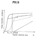
- the object of the present invention is to provide an injection timer capable of achieving both an improvement in accuracy of injection timing control and in anti-pollution characteristics at startup and which is also capable of supporting a fuel injection system with the pump chamber pressure characteristics indicated with the solid line in FIG. 9.
- the injection timing device for a fuel injection system comprises a timing device that adjusts the fuel injection start timing by causing pressure of the fuel in the pump chamber to work on a timer piston and by adjusting that pressure, a means for timer position detection for detecting the actual position of the timer piston, a means for timer target position setting for setting a target position for the timer piston, a means for feedback control for performing feedback control of the timing device in such a manner that the actual position of the timer piston moves toward the target position, a means for error decision making for determining that an error has occurred in the timing device control system, a means for open loop control for performing open loop control of the timer when the means for error decision making has determined that an error has occurred, a means for startup decision making for determining that the operation is at startup time and a means for control that cancels the decision made by the means for error decision making that an error has occurred, maintaining feedback control when it has been decided by the means for startup decision making that the operation is at startup time.
- the operation when it has been decided by the means for startup decision making that the operation is at startup time, the operation does not shift to open loop control of the timer, even when the engine rotation rate is in the extremely low rotation rate range, thereby maintaining feedback control and assuring stable control at the time of startup, thus achieving the object described above.
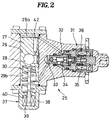
- a distributor type fuel injection pump 1 is provided with a housing 3 that is mounted with an actuator 2, i.e., a so-called electronic governor.
- an actuator 2 i.e., a so-called electronic governor.
- a drive shaft 4 is inserted.
- One end of the drive shaft 4 projects out to the outside of the housing 3 to receive drive torque from the engine (not shown).
- the other end of the drive shaft 4 extends to a pump chamber 5 inside the housing 3 and a feed pump 6 is linked to the drive shaft 4 so that fuel from a fuel tank (not shown) is supplied to the pump chamber 5 by the feed pump 6.
- a plunger 7 is mounted in a plunger barrel 8 in such a manner that it can slide freely.
- the base portion of the plunger 7 is pressed into contact with a cam disk 9 by a plunger spring 10.
- the cam disk 9 is connected to the drive shaft 4 via a coupling 11 in such a manner that it can travel in the direction of the axis.
- the cam disk 9 is also in contact with a roller 13 that is supported by a roller holder 12 so that the cam disk 9 simultaneously effects reciprocal movement for fuel intake and force feed as well as rotational movement for distributing fuel to the plunger 7.
- the fuel that has been supplied into the pump chamber 5 via an oil transfer pump flows into a compression space 16 that is enclosed by the plunger barrel 8 and the plunger 7 via one of the intake grooves 15 formed in the direction of the shaft of the plunger 7 at its front end, from an intake port 14.
- the intake port 14 becomes separated from the intake groove 15 and the fuel that has been compressed in the compression space 16 travels through a longitudinal hole 17 in the plunger 7 to enter one of the distribution passages 18 from a distribution port. It is then supplied to an injection nozzle (not shown) via a delivery valve 19 to be injected into a cylinder of the engine.
- a control sleeve 20 is externally fitted on the portion of the plunger 7 that projects out from the plunger barrel 8 in such a manner that it can slide freely, and when a cutoff port 21, which communicates with the longitudinal hole 17 in the plunger 7, passes beyond the edge of the control sleeve 20 to open into the pump chamber 5, the compressed fuel flows out to the pump chamber 5 to stop the delivery of fuel to the injection nozzle, ending the injection.
- the injection end i.e., the injection quantity
- the injection quantity can be controlled through positional adjustment of the control sleeve 20.
- the front end of a shaft 23, which is mounted at a rotor 22 of the actuator 2 is connected to the control sleeve 20.
- the front end of the shaft 23 decenters from the shaft axis and consequently, the actuator 2 can adjust the position of the control sleeve 20 through the rotation of the rotor.
- a timing device 25 is provided with a timer piston 27 which is stored in a cylinder 26 located below the roller holder 12 in such a manner that it can slide freely.
- the timer piston 27 is linked to the roller holder 12 via a lever 28 and, as a result, the injection timing can be adjusted by rotating the roller holder 12 through the sliding motion of the timer piston 27.
- a high pressure chamber 29a is formed, into which high pressure fuel is induced from the pump chamber via a constricted passage 42.
- a low pressure chamber 29b is formed, which communicates with the intake path of the feed pump.
- a timer spring 30 is provided at the low pressure chamber 29b and a constant force is applied to the timer piston 27 toward the high pressure chamber by the timer spring 30. Consequently, the timer piston 27 stops at a position where the spring pressure of the timer spring 30 and the fuel pressure in the high pressure chamber are in balance.
- the timer piston 27 travels toward the low pressure chamber against the force of the timer spring 30 to rotate the roller holder 12 in the direction in which the injection timing is hastened, to advance the injection timing.
- the timer piston 27 travels toward the high pressure chamber to rotate the roller holder 12 in the direction in which the injection timing is delayed to retard injection timing.
- timing control valve 31 is provided with a fuel intake 32 that communicates with the high pressure chamber 29a at the side surface portion and it is also is provided with a fuel outlet 33 that communicates with the low pressure chamber 29b at the front end portion.
- a needle 34 is housed, which opens and closes the communicating passage between the fuel intake 32 and the fuel outlet 33.
- a constant force is applied to the needle 34 by a spring 35 in the direction in which communication between the fuel intake 32 and the fuel outlet 33 is cut off.
- electricity is supplied to a solenoid 36, the needle 34 is attracted to the solenoid 36 against the force of the spring 35 so that fuel intake 32 and the fuel outlet 33 communicate.
- the high pressure chamber 29a and the low pressure chamber 29b are completely cut off from each other and when an electric current is running to the solenoid 36, the high pressure chamber 29a and the low pressure chamber 29b communicate, to reduce the pressure in the high pressure chamber 29a.
- the timer piston 27 moves to the position where it is in balance with the force of the timer spring 30 to change the injection timing.
- the pressure in the high pressure chamber 29a is adjusted through duty ratio control of the timing control valve.
- This duty ratio is controlled by the control unit 41 (shown in FIG. 1)and when the duty ratio is at 0%, the timing control valve 31 is in the full open state and the injection timing is at its most delayed angle.
- the duty ratio is at 100%, the timing control valve 31 is in the full closed state and the injection timing is at its most advanced angle.
- a timer position sensor 37 for detecting the position of the timer piston is provided in the housing.
- This timer position sensor 37 may be located, for instance, toward the low pressure chamber and it is constituted with a detection coil 39 provided on the sensor main body 38 and a rod 40 mounted on the timer piston 27.
- An output signal TPSIST from the timer position sensor 37 is sent to the control unit 41 where it is processed.
- the control unit 41 is structured with a drive circuit that drives the actuator 2 and the timing control valve 31, a microcomputer that controls the drive circuit, an input circuit for inputting signals to the microcomputer, and the like.
- the microcomputer is provided with a central processing unit (CPU), a ROM, a RAM, an A/D converter and the like.
- the engine rotation rate N (the output from the engine rotation rate sensor), the accelerator position signal ACCEL, which indicates the quantity of accelerator pedal movement, the water temperature signal TW, which indicates the temperature of the engine cooling water, and the like, as well as the signal TPSIST from the timer position sensor 37 are input to the input circuit of the control unit 41. These signals are processed and then used to drive and control the actuator 2 and the timing control valve 31 in conformance to a specific program.
- FIG. 3 an example of timer control performed by the control unit 41 is shown in a block diagram.
- the optimal injection timing (IT_LD), which corresponds to a given set of operating conditions, is calculated using a data map (load timer characteristics) of the optimal injection timing, which is determined in advance based upon the engine rotation rate N and the accelerator position ACCEL. Then the timer piston position that corresponds to the optimal injection timing is calculated (block 50).
- an injection timing correction quantity for startup that corresponds to the set of operating conditions is determined from the data of the injection timing correction quantity (IT_TWS) that have been mapped in advance based upon the relationship between the engine rotation rate N and the water temperature TW, and the correction quantity for the timer piston position that corresponds to the injection timing correction quantity is calculated (block 52). If it is during normal running, an injection timing correction quantity for running that corresponds to the set of operating conditions is determined from the data of the injection timing correction quantity (IT_TW) that have been mapped in advance based upon the relationship between the engine rotation rate N and the water temperature TW, and the correction quantity for the timer piston position that corresponds to the injection timing correction quantity is calculated (block 54).
- the timer piston position (TPSSOL: target timer piston position) which achieves the target injection timing is calculated by adding the correction quantity calculated in block 52 or block 54 to the timer piston position calculated in block 50.
- the difference between the target timer piston position (TPSSOL) and the measured timer piston position (TPSIST: actual timer piston position) is determined and the adjustment quantity (TPSCLOSE), with which PID control is performed to keep this difference within a specific range is calculated (block 56).
- a drive pulse which corresponds to the adjustment quantity is output to the TCV (block 58).
- the injection timing (D_LD) that corresponds to a given set of operating conditions is calculated using a specific data map (open loop characteristics) based upon the engine rotation rate N and the accelerator position ACCEL and then the timer piston position that corresponds to this injection timing is calculated (block 60). If the operation is at startup (start mode), an injection timing correction quantity for startup that corresponds to the set of operating conditions is determined from the data of the mapped in advance, based upon the relationship between the engine rotation rate N and the water temperature TW, and a correction quantity for the timer piston position that corresponds to that injection timing correction quantity is calculated (block 62).
- a correction quantity for running that corresponds to the set of operating conditions is determined from the data of the injection timing correction quantity (D_TW) that have been mapped in advance based upon the relationship between the engine rotation rate N and the water temperature TW, and the correction quantity for the timer piston position that corresponds to the injection timing correction quantity is determined (block 64). Then, the control quantity (TPSOPEN) for the timer piston position in open loop control is calculated by adding the correction quantity calculated in either block 62 or block 64 to the timer piston position calculated in block 60. After this, a drive pulse which corresponds to this control quantity is output to the TCV (block 58).
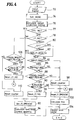
- FIG. 4 is a flow chart of a more specific example of control and the following is its explanation.
- the control unit 41 is initialized when the start switch (ST SW) is turned ON and analog signals from the various sensors of the injection pump 1, including an output signal (TPSIST) from the timer position sensor 37, the engine rotation rate (N), the accelerator position signal (ACCEL) and the water temperature signal (TW), are sequentially converted into digital signals by the A/D converter to be input to the control unit 41 (step 72).
- ST SW start switch
- TPSIST output signal
- N engine rotation rate
- ACCEL accelerator position signal
- TW water temperature signal
- step 74 the mode setting processing described below is executed and then in step 76, the processing for calculating the target injection timing is executed.
- step 200 if it has been decided in step 200 that the flag (_ST_MODE) is set, a decision is made in step 208 as to whether or not the flag (_ST) is set and also a decision is made in step 210 as to whether or not the engine rotation rate N is 0. If the engine rotation rate becomes 0 after the start switch has been operated, the operation proceeds to step 212 in which the flag (_ST_MODE) is reset. If, on the other hand, the engine rotation rate is not 0 after the start switch has been operated, then the operation proceeds to step 214, in which a decision is made as to whether or not the engine rotation rate N is equal to or exceeds a specific rotation rate (N_ST: 650 rpm, for instance).
- N_ST 650 rpm
- the operation may be switched from the control processing for the start mode to the control processing for the normal running mode, the flag (_ST_MODE) is reset. However, if N_ST > N r 0, the control processing for the start mode is maintained.
- step 76 the calculation for the target injection timing performed in step 76 is carried out, as shown in FIG. 6, by first making a decision in step 300 as to whether or not the flag (_ST_MODE,) for indicating that the start mode is in effect. If the flag (_ST_MODE) is set, the operation proceeds to step 302, in which a correction quantity for injection timing in the start mode is calculated. At this point, the injection timing correction quantity for the start mode is calculated by storing in advance the correct injection timing correction quantities relative to the engine rotation rates N and the temperatures TW of the engine cooling water in the ROM as a data map and by using this data map with the input of N and TW, as explained earlier.
- step 304 in which an injection timing correction quantity for the normal running mode is calculated.
- the injection timing correction quantity for the normal running mode is calculated by storing in advance the injection timing correction quantities for the running state in ROM as a data map and by using this data map with the input of N and TW.
- step 306 the optimal target injection timing relative to the engine state at that point, is calculated as a target timer piston position (TPSSOL), by taking into consideration the correction quantity described above, in the manner described earlier.
- TPSSOL target timer piston position
- step 77 a decision is made in step 77 as to whether or not there is an error in the timer position sensor (TPS). Also, in step 78 a decision is made as to whether or not the injection timing control disable flag (_IT_NG) for indicating that the control for the injection timing is disabled has been set.
- _IT_NG injection timing control disable flag
- step 80 a decision is made in step 80 as to whether or not the starter motor has been turned ON (the ST SW has been turned ON ) to set the flag (_ST), and in step 82, a decision is made as to whether or not the engine rotation rate N is equal to or less than a specific rotation rate (N_IT_OPEN: 400 rpm, for instance) that requires open loop control of the injection timing.
- N_IT_OPEN 400 rpm, for instance
- step 84 If the starter is engaged or if, after the startup of the starter, the engine rotation rate exceeds the specific rotation rate (N_IT_OPEN), the operation proceeds to step 84. However, if the engine rotation rate is equal to or less than the specific rotation rate (N_IT_OPEN) after the starter has been operated, the operation proceeds to step 92 in which the open loop control flag (_IT_OPENCNT) for indicating that open loop control is to be executed for the injection timing is set. In step 94 that follows, the open loop control quantity is calculated.
- step 84 a decision is made as to whether or not the engine rotation rate N is equal to or exceeds a required specific rotation rate (N_IT_DIAG: 650 rpm, for instance) for detecting an injection timing servo error, and then in step 86, a decision is made as to whether or not the water temperature TW exceeds a required specific water temperature (TW_IT_WAX: -5°C, for instance) for detecting an injection timing servo error.
- N_IT_DIAG 650 rpm, for instance
- step 88 a decision is made as to whether or not the difference (
- DCT_IT_NG count on the timer counter
- step 77 If it has been decided in step 77 that there is an error in the TPS, the operation proceeds to step 92, in which the open loop control flag (_IT_OPENCNT) for indicating that open loop control of the injection timing is to be performed is set and in step 94, the open loop control quantity is calculated.
- the open loop control flag (_IT_OPENCNT) for indicating that open loop control of the injection timing is to be performed is set and in step 94, the open loop control quantity is calculated.
- step 84 - 90 In relation to the conditions for determining that injection timing control is disabled (steps 84 - 90), if the engine rotation rate N falls short of the rotation rate (N_IT_DIAG) required for determining that there is an error in the timing device control system, if the water temperature TW is equal to or less than the TW_IT_WAX, or if the
- N_IT_DIAG the rotation rate required for determining that there is an error in the timing device control system
- step 100 the adjustment quantity (TPSCLOSE) with which PID control is performed to keep the difference between the target timer piston position (TPSSOL) and the actual timer piston position (TPSIST) within a specific range is calculated, and in step 104, and a drive pulse that corresponds to the adjustment quantity is output to the TCV 31.
- TPSCLOSE the adjustment quantity with which PID control is performed to keep the difference between the target timer piston position (TPSSOL) and the actual timer piston position (TPSIST) within a specific range is calculated, and in step 104, and a drive pulse that corresponds to the adjustment quantity is output to the TCV 31.
- step 400 a decision is made as to whether or not the flag (_ST_MODE) for indicating that the start mode is in effect has been set and if the flag (_ST_MODE) has been set, the operation proceeds to step 402. If it has been reset, the operation proceeds to step 404.
- step 402 the injection timing correction quantity for the start mode in open loop control is calculated.
- the injection timing correction quantity for the start mode is calculated by storing in advance the correct injection timing correction quantities relative to the engine rotation rates N and the temperatures TW of the engine cooling water in ROM as a data map and by using this data map with the input of N and TW as explained earlier.
- the injection timing correction quantity in the normal running mode in open loop control is calculated.
- the injection timing correction quantity in the normal running mode is calculated by storing in advance the injection timing correction quantities for the running state in ROM as a data map and by using this data map with the input of N and TW.
- step 406 the optimal target injection timing relative to the engine state at that point in time is calculated as the control quantity (TPSOPEN) for the timer piston position by taking into consideration the correction quantity described above, in the manner described earlier.
- step 94 the operation proceeds to step 104 in which a drive pulse that corresponds to the control quantity is output to the TCV 31.
- step 78 if it has been decided in step 78 that the injection timing control disable flag (_IT_NG) has been set, the operation proceeds to steps 106 and 108, in which a decision for returning the operation from open loop control to feedback control of the injection timing is made.
- a decision is made as to whether or not the
- step 106 If, in step 106, it has been decided that the
- DCT_IT_OK the count on the timer counter
- step 112 in which the injection timing control disable flag (_IT_NG) is reset before proceeding to the processing performed in step 100 and beyond, to return to feedback control.
- the operation shifts from feedback control to open loop control when (1) the switch (ST SW) for engaging the starter is OFF (after the operation of the starter at the time of startup is complete) and the engine rotation rate is equal to or less than the specific rotation rate (N_IT_OPEN), (2) there is an error in the timer position sensor or (3) the engine rotation rate N is equal to or exceeds the specific rotation rate (N_IT_DAIG), the water temperature TW is higher than the specific temperature (TW_IT_WAX), the difference between the target timer piston position and the actual timer piston position is greater than the specific quantity and all these conditions are maintained for a period equal to or exceeding a specific length of time (5 seconds).
- the operation shifts from open loop control to feedback control when either the switch for engaging the starter is turned ON or the engine rotation rate exceeds the specific rotation rate, the timer position sensor is operating normally, the difference between the target timer piston position and the actual timer piston position is smaller than the specific quantity and these conditions are maintained for at least a specific length of time (5 seconds).
- step 80 As indicated with the solid line in FIG. 9, if the pump chamber pressure is set at a high level, feedback control of the injection timing is possible at startup even in the extremely low rotation rate range.
- the operation shifts from step 80 to step 84 even when the engine rotation rate N at startup is less than the N_IT_OPEN, the operation does not shift to open loop control in the extremely low rotation rate range at startup and feedback control is maintained.
- the present invention since, even when the output level of the engine rotation rate sensor is too low to be recognized by the control unit at extremely low rotation rates, i.e., even when the control accuracy is degraded, if a decision for switching to open loop control is implemented with the output from the engine rotation rate sensor, feedback control, in which the TPSIST conforms to the TPSSOL is maintained, and it is possible to improve control accuracy at startup.
- feedback control since feedback control is assured even in the rotation rate range that is equal to or less than the N_IT_OPEN at startup, anti-pollution measures can be accommodated. After such feedback control is performed at startup and the engine rotation has temporarily increased, if for some reason the engine rotation rate becomes equal to or less than the N_IT_OPEN, the operation shifts from step 82 to step 92 and open loop control is performed.
- step 86 to step 98 since the operation shifts from step 86 to step 98 if the water temperature falls so low as to induce the fuel to become semi-solid, feedback control is continued in this case, too, without deciding that there is an error in the timing device control system, and the heat in the solenoid 36 generated by supplying an electric current to the TCV is passed on to the fuel in the fuel passages leading to the housing of the injection pump and the TCV, thereby eliminating the semi-solidification of the fuel at an early stage.
Landscapes
- Engineering & Computer Science (AREA)
- Chemical & Material Sciences (AREA)
- Combustion & Propulsion (AREA)
- Mechanical Engineering (AREA)
- General Engineering & Computer Science (AREA)
- Electrical Control Of Air Or Fuel Supplied To Internal-Combustion Engine (AREA)
- High-Pressure Fuel Injection Pump Control (AREA)
- Fuel-Injection Apparatus (AREA)
Applications Claiming Priority (2)
| Application Number | Priority Date | Filing Date | Title |
|---|---|---|---|
| JP209131/94 | 1994-08-10 | ||
| JP6209131A JPH0861128A (ja) | 1994-08-10 | 1994-08-10 | 燃料噴射装置の噴射時期調整装置 |
Publications (3)
| Publication Number | Publication Date |
|---|---|
| EP0697511A2 true EP0697511A2 (de) | 1996-02-21 |
| EP0697511A3 EP0697511A3 (de) | 1997-02-26 |
| EP0697511B1 EP0697511B1 (de) | 1998-07-08 |
Family
ID=16567807
Family Applications (1)
| Application Number | Title | Priority Date | Filing Date |
|---|---|---|---|
| EP95305453A Expired - Lifetime EP0697511B1 (de) | 1994-08-10 | 1995-08-04 | Einrichtung zur Verstellung des Förderbeginnes eines Brennstoffeinspritzsystems |
Country Status (5)
| Country | Link |
|---|---|
| US (1) | US5531204A (de) |
| EP (1) | EP0697511B1 (de) |
| JP (1) | JPH0861128A (de) |
| KR (1) | KR0144603B1 (de) |
| DE (1) | DE69503327T2 (de) |
Cited By (1)
| Publication number | Priority date | Publication date | Assignee | Title |
|---|---|---|---|---|
| EP0812982A3 (de) * | 1996-06-11 | 2000-07-12 | Toyota Jidosha Kabushiki Kaisha | Kraftstoffeinspritzungssteuergerät für einen elektronisch geregelten Dieselmotor |
Families Citing this family (6)
| Publication number | Priority date | Publication date | Assignee | Title |
|---|---|---|---|---|
| JP3594366B2 (ja) * | 1995-06-30 | 2004-11-24 | 三菱自動車工業株式会社 | エンジンの燃料噴射時期制御装置 |
| JP3572433B2 (ja) * | 1997-01-31 | 2004-10-06 | 日産自動車株式会社 | ディーゼルエンジン用燃料噴射ポンプの燃料噴射時期制御装置 |
| JPH10274059A (ja) * | 1997-03-28 | 1998-10-13 | Zexel Corp | 分配型燃料噴射装置のタイマ装置 |
| JP2000345903A (ja) * | 1999-06-01 | 2000-12-12 | Isuzu Motors Ltd | 電子燃料噴射装置 |
| KR20040048721A (ko) * | 2002-12-04 | 2004-06-10 | 현대자동차주식회사 | 초기 듀티 제어에 의한 진각 분사시기 제어방법 |
| DE102016208086A1 (de) * | 2016-05-11 | 2017-11-16 | Robert Bosch Gmbh | Verfahren zur Regelung eines Injektors zur Einspritzung von Kraftstoff |
Family Cites Families (11)
| Publication number | Priority date | Publication date | Assignee | Title |
|---|---|---|---|---|
| JPS551418A (en) * | 1978-06-16 | 1980-01-08 | Diesel Kiki Co Ltd | Injection timing device for distribution-type fuel injection pump |
| US4397285A (en) * | 1981-07-15 | 1983-08-09 | Physics International Company | Closed loop diesel engine control |
| JPS58172437A (ja) * | 1982-04-02 | 1983-10-11 | Toyota Motor Corp | デイ−ゼルエンジンの燃料噴射量制御装置 |
| JPS5939942A (ja) * | 1982-08-30 | 1984-03-05 | Toyota Motor Corp | デイ−ゼルエンジンの燃料噴射制御装置 |
| US4476837A (en) * | 1982-12-07 | 1984-10-16 | Stanadyne, Inc. | Method and system for fuel injection timing |
| JPS59215931A (ja) * | 1983-05-24 | 1984-12-05 | Diesel Kiki Co Ltd | 燃料噴射ポンプの進角制御装置 |
| JPS60184944A (ja) * | 1984-03-02 | 1985-09-20 | Toyota Motor Corp | 電子制御デイ−ゼルエンジンの気筒別燃料噴射量制御方法 |
| JPS60259732A (ja) * | 1984-05-09 | 1985-12-21 | Diesel Kiki Co Ltd | 分配型燃料噴射ポンプの噴射時期調整装置 |
| FR2569774B1 (fr) * | 1984-09-06 | 1986-09-05 | Cav Roto Diesel | Perfectionnements aux pompes d'injection de combustible pour moteur a combustion interne |
| DE3729636A1 (de) * | 1987-09-04 | 1989-03-16 | Bosch Gmbh Robert | Verfahren zur steuerung der zeit der kraftstoffhochdruckfoerderung einer kraftstoffeinspritzpumpe |
| US5263457A (en) * | 1989-12-06 | 1993-11-23 | Robert Bosch Gmbh | Fuel injection pump for internal combustion engines |
-
1994
- 1994-08-10 JP JP6209131A patent/JPH0861128A/ja active Pending
-
1995
- 1995-08-02 US US08/510,536 patent/US5531204A/en not_active Expired - Fee Related
- 1995-08-04 EP EP95305453A patent/EP0697511B1/de not_active Expired - Lifetime
- 1995-08-04 DE DE69503327T patent/DE69503327T2/de not_active Expired - Fee Related
- 1995-08-10 KR KR1019950024684A patent/KR0144603B1/ko not_active Expired - Fee Related
Cited By (1)
| Publication number | Priority date | Publication date | Assignee | Title |
|---|---|---|---|---|
| EP0812982A3 (de) * | 1996-06-11 | 2000-07-12 | Toyota Jidosha Kabushiki Kaisha | Kraftstoffeinspritzungssteuergerät für einen elektronisch geregelten Dieselmotor |
Also Published As
| Publication number | Publication date |
|---|---|
| KR0144603B1 (ko) | 1998-08-17 |
| JPH0861128A (ja) | 1996-03-05 |
| US5531204A (en) | 1996-07-02 |
| DE69503327D1 (de) | 1998-08-13 |
| EP0697511A3 (de) | 1997-02-26 |
| DE69503327T2 (de) | 1999-04-08 |
| EP0697511B1 (de) | 1998-07-08 |
| KR960008018A (ko) | 1996-03-22 |
Similar Documents
| Publication | Publication Date | Title |
|---|---|---|
| US4625697A (en) | Automotive engine control system capable of detecting specific engine operating conditions and projecting subsequent engine operating patterns | |
| KR101154128B1 (ko) | 내연 기관 제어 방법 및 장치 | |
| KR890005043B1 (ko) | 내연기관용 연료분사장치 | |
| JPS60145440A (ja) | 燃料噴射量制御装置 | |
| US6024062A (en) | Hydraulic apparatus for adjusting the timing of opening and closing of an engine valve | |
| KR100352197B1 (ko) | 내연기관의제어와관련하여미래의부하신호를예측하는방법및장치 | |
| US5531204A (en) | Injection timing device for fuel injection system | |
| KR100500358B1 (ko) | 내연기관의 밸브 타이밍 제어장치 | |
| KR900001624B1 (ko) | 압력응동식 작동자의 제어장치 및 엔진의 배기가스 재순환 제어장치 | |
| JP3540095B2 (ja) | ディーゼルエンジンの噴射時期制御装置における異常判定装置 | |
| US4903658A (en) | Control method for idling speed of an engine | |
| JP4173695B2 (ja) | 内燃機関の駆動方法 | |
| US4456831A (en) | Failsafe for an engine control | |
| JP3306687B2 (ja) | 電子式燃料噴射装置の噴射時期調整装置 | |
| EP0598602B1 (de) | Einrichtung zur Verstellung des Förderbeginnes eines elektronischen Brennstoffeinspritzsystems | |
| EP0425798B1 (de) | Kraftstoffeinspritzungssteuergerät und Methode für einen Dieselmotor | |
| EP0657638B1 (de) | Einspritzzeitpunktverstellungsvorrichtung für ein elektronisches Kraftstoffeinspritzsystem | |
| US5909722A (en) | Method and device for controlling a final controlling element in closed-loop | |
| EP0761954A1 (de) | Kraftstoffeinspritzregelsystem für einen Dieselmotor | |
| JP3644060B2 (ja) | ディーゼルエンジンの燃料噴射制御装置 | |
| JPH0370497A (ja) | ステップモータ制御装置 | |
| JP3327087B2 (ja) | ディーゼルエンジンの制御装置 | |
| JPH04342833A (ja) | 燃料噴射制御装置 | |
| JPS60201051A (ja) | 内燃機関の燃料噴射時期制御装置 | |
| JPH09170479A (ja) | 燃料調量装置の制御方法および装置 |
Legal Events
| Date | Code | Title | Description |
|---|---|---|---|
| PUAI | Public reference made under article 153(3) epc to a published international application that has entered the european phase |
Free format text: ORIGINAL CODE: 0009012 |
|
| AK | Designated contracting states |
Kind code of ref document: A2 Designated state(s): DE GB |
|
| 17P | Request for examination filed |
Effective date: 19961010 |
|
| PUAL | Search report despatched |
Free format text: ORIGINAL CODE: 0009013 |
|
| AK | Designated contracting states |
Kind code of ref document: A3 Designated state(s): DE GB |
|
| 17Q | First examination report despatched |
Effective date: 19970610 |
|
| GRAG | Despatch of communication of intention to grant |
Free format text: ORIGINAL CODE: EPIDOS AGRA |
|
| GRAG | Despatch of communication of intention to grant |
Free format text: ORIGINAL CODE: EPIDOS AGRA |
|
| GRAG | Despatch of communication of intention to grant |
Free format text: ORIGINAL CODE: EPIDOS AGRA |
|
| GRAH | Despatch of communication of intention to grant a patent |
Free format text: ORIGINAL CODE: EPIDOS IGRA |
|
| GRAH | Despatch of communication of intention to grant a patent |
Free format text: ORIGINAL CODE: EPIDOS IGRA |
|
| GRAA | (expected) grant |
Free format text: ORIGINAL CODE: 0009210 |
|
| AK | Designated contracting states |
Kind code of ref document: B1 Designated state(s): DE GB |
|
| REF | Corresponds to: |
Ref document number: 69503327 Country of ref document: DE Date of ref document: 19980813 |
|
| PLBE | No opposition filed within time limit |
Free format text: ORIGINAL CODE: 0009261 |
|
| STAA | Information on the status of an ep patent application or granted ep patent |
Free format text: STATUS: NO OPPOSITION FILED WITHIN TIME LIMIT |
|
| 26N | No opposition filed | ||
| PGFP | Annual fee paid to national office [announced via postgrant information from national office to epo] |
Ref country code: DE Payment date: 20010730 Year of fee payment: 7 |
|
| PGFP | Annual fee paid to national office [announced via postgrant information from national office to epo] |
Ref country code: GB Payment date: 20010801 Year of fee payment: 7 |
|
| REG | Reference to a national code |
Ref country code: GB Ref legal event code: IF02 |
|
| PG25 | Lapsed in a contracting state [announced via postgrant information from national office to epo] |
Ref country code: GB Free format text: LAPSE BECAUSE OF NON-PAYMENT OF DUE FEES Effective date: 20020804 |
|
| PG25 | Lapsed in a contracting state [announced via postgrant information from national office to epo] |
Ref country code: DE Free format text: LAPSE BECAUSE OF NON-PAYMENT OF DUE FEES Effective date: 20030301 |
|
| GBPC | Gb: european patent ceased through non-payment of renewal fee |
Effective date: 20020804 |