EP0696153A1 - Kommunikationsverfahren mit allgemeiner benutzung eines mobilkommunikationsendgerätes und kommunikationssystemsteuereinrichtung dafür - Google Patents
Kommunikationsverfahren mit allgemeiner benutzung eines mobilkommunikationsendgerätes und kommunikationssystemsteuereinrichtung dafür Download PDFInfo
- Publication number
- EP0696153A1 EP0696153A1 EP95909952A EP95909952A EP0696153A1 EP 0696153 A1 EP0696153 A1 EP 0696153A1 EP 95909952 A EP95909952 A EP 95909952A EP 95909952 A EP95909952 A EP 95909952A EP 0696153 A1 EP0696153 A1 EP 0696153A1
- Authority
- EP
- European Patent Office
- Prior art keywords
- mobile communication
- communication terminal
- communication system
- communication network
- terminal
- Prior art date
- Legal status (The legal status is an assumption and is not a legal conclusion. Google has not performed a legal analysis and makes no representation as to the accuracy of the status listed.)
- Granted
Links
Images


Classifications
-
- H—ELECTRICITY
- H04—ELECTRIC COMMUNICATION TECHNIQUE
- H04W—WIRELESS COMMUNICATION NETWORKS
- H04W60/00—Affiliation to network, e.g. registration; Terminating affiliation with the network, e.g. de-registration
-
- H—ELECTRICITY
- H04—ELECTRIC COMMUNICATION TECHNIQUE
- H04B—TRANSMISSION
- H04B7/00—Radio transmission systems, i.e. using radiation field
-
- H—ELECTRICITY
- H04—ELECTRIC COMMUNICATION TECHNIQUE
- H04W—WIRELESS COMMUNICATION NETWORKS
- H04W8/00—Network data management
- H04W8/02—Processing of mobility data, e.g. registration information at HLR [Home Location Register] or VLR [Visitor Location Register]; Transfer of mobility data, e.g. between HLR, VLR or external networks
- H04W8/04—Registration at HLR or HSS [Home Subscriber Server]
-
- H—ELECTRICITY
- H04—ELECTRIC COMMUNICATION TECHNIQUE
- H04W—WIRELESS COMMUNICATION NETWORKS
- H04W84/00—Network topologies
- H04W84/02—Hierarchically pre-organised networks, e.g. paging networks, cellular networks, WLAN [Wireless Local Area Network] or WLL [Wireless Local Loop]
- H04W84/04—Large scale networks; Deep hierarchical networks
- H04W84/042—Public Land Mobile systems, e.g. cellular systems
-
- H—ELECTRICITY
- H04—ELECTRIC COMMUNICATION TECHNIQUE
- H04W—WIRELESS COMMUNICATION NETWORKS
- H04W84/00—Network topologies
- H04W84/02—Hierarchically pre-organised networks, e.g. paging networks, cellular networks, WLAN [Wireless Local Area Network] or WLL [Wireless Local Loop]
- H04W84/10—Small scale networks; Flat hierarchical networks
- H04W84/16—WPBX [Wireless Private Branch Exchange]
-
- H—ELECTRICITY
- H04—ELECTRIC COMMUNICATION TECHNIQUE
- H04W—WIRELESS COMMUNICATION NETWORKS
- H04W88/00—Devices specially adapted for wireless communication networks, e.g. terminals, base stations or access point devices
- H04W88/02—Terminal devices
- H04W88/06—Terminal devices adapted for operation in multiple networks or having at least two operational modes, e.g. multi-mode terminals
Definitions
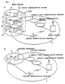
- the present invention relates to a mobile communication terminal sharing method for sharing mobile communication terminals of a mobile communication network, for example, as mobile communication terminals of an indoor radio communication system, or as handsets of a cordless telephone, and the invention also pertains to a communication system control device which permits the sharing of such mobile communication terminals.
- an indoor radio communication system With an indoor radio communication system, its mobile communication terminals can be interconnected for communications via a private branch exchange (PBX) in a building or underground shopping center, for example; moreover, they can be connected via the PBX to subscriber lines of a public communication network to which the indoor communication system is connected, and hence they are allowed to communicate with terminals of the public communication network.
- PBX private branch exchange
- service areas of the public communication network and the mobile communication network are set up geographically overlapping; when a mobile communication terminal of the mobile communication system happens to stay in the overlapping area, the connection of an incoming call to the mobile communication terminal via the indoor communication system would allow the sending power of the terminal to be small, reducing power consumption accordingly.
- An indoor communication system 70 subscribe to the public fixed communication network 2.
- its subscriber lines are connected via a private branch exchange (PBX) 7, in this example, to a plurality of indoor base stations 301 to 303; the indoor base stations 301 to 303 can be connected via electric waves (radio waves) to mobile communication terminals 10 in respective service areas 51 to 53; the mobile communication terminals 10 can communicate with those in other service areas via the indoor base stations and the PBX 7 and, moreover, they can be connected to the subscriber lines via the indoor base stations and the PBX 7 for communication with terminals of the public fixed communication network 2.
- the service areas 51 to 53 are, for example, respective floors in a building, individual buildings on a large premises, or split areas of an underground shopping center.
- the service area of the mobile communication network 1 is split into a plurality of zones (or cells) and the mobile communication terminal 10 in one of the zones 3 is connected via a radio circuit or channel to a base station of that zone 3, through which it is allowed to communicate with other mobile communication terminals in the mobile communication network 1 or fixed terminals of the public fixed communication network 2 and the indoor communication system 70.
- the mobile communication network 1 and the public fixed communication network 2 are far larger in area than the zone 3, but in Fig. 1 the networks are shown to be smaller than the zone for convenience' sake; moreover, although the zone 3 is situated in the mobile communication network 1 as described previously, the latter is shown to be included in the former.
- the zone 3 and the service areas 51 to 53 of the indoor communication system 70 geographically overlap; when the mobile communication terminal 10 of the mobile communication network 1 happens to stay in such an overlapping area, it is common practice in the art to use the mobile communication terminal 10 also as a mobile communication terminal of the indoor communication system so that an incoming call to the mobile communication terminal 10 is related thereto in the overlapping area from the mobile communication network 1 via the public fixed communication network 2 and the indoor communication system 70.
- one of destination address (subscribers' telephone numbers) of the indoor communication system 70 is fixedly preassigned as an incoming call forwarding destination address to the mobile communication terminal 10 so that when it is in the overlapping area, the incoming call is forwarded to the destination address.
- an incoming call to the mobile communication terminal 10 can be connected thereto via the public fixed communication network 2 and the base station 8 by assigning a subscriber's number of the cordless telephone 70' to the mobile communication terminal 10 as the incoming call forwarding destination address.
- the subscriber's number of a cordless telephone installed in that house is assigned as the incoming call forwarding destination address to the mobile communication terminal and an incoming call forwarding registration is made accordingly.
- the indoor communication system and the cordless telephone which utilize radios subscribed to the public fixed communication network or public mobile communication network as mentioned above will hereinafter be referred to as a second communication system and mobile communication terminals of the indoor communication system and the handset of the cordless telephone will hereinafter be referred to as mobile communication terminals.
- the mobile communication terminal of the mobile communication network when the mobile communication terminal of the mobile communication network is in the coverage of the second communication system and shared as the mobile communication terminal of the latter, it is conventional that a destination address is fixedly assigned in that mobile communication terminal.
- the number of subscriber's numbers of the second communication system is one in the case of the cordless telephone and is not so large in the case of the indoor communication system either, and the number of addresses that can be assigned as incoming call forwarding destination addresses to the mobile communication terminals is limited to the number of subscriber's numbers belonging to the second communication system.
- the address cannot be used as the incoming call forwarding destination address for another mobile communication terminal having newly entered the coverage of the second communication system. That is, the prior art does not efficiently use the subscriber's numbers (destination addresses) of the second communication system as incoming call forwarding destination addresses of mobile communication terminals in the prior art.
- the relationship between the destination address and the mobile communication terminal can freely be changed and stored in the second communication system, and when requested to start the use of the mobile communication terminal therein, the second communication system assigns to the mobile communication terminal a destination address for use in the second communication system, automatically stores the destination address as location registration area information of a location register of the mobile communication terminal or an incoming call forwarding destination address, enabling the mobile communication terminal to receive an incoming call through the use of the same number as that when it is in the mobile communication network.
- the destination address assigned to the mobile communication terminal in the second communication system is allowed to use as a destination address of the mobile communication terminal only while it stays in the second communication system, and when the mobile communication terminal has left it, the destination address assigned to the terminal is released therefrom so that it can be reused (assigned to) for another mobile communication terminal.
- the communication system to which the second communication system is directly connected constitutes a digital communication network of a numbering system composed of subscriber's numbers and sub-addresses like ISDN
- the sub-addresses are assigned to mobile communication terminals in place of the destination addresses and they are revoked (cancelled) in the same manner as the destination addresses. This permits efficient use of the subscriber's numbers.
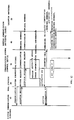
- Fig. 1 illustrates in block form examples of systems to which the method of the present invention is applied, A showing the case of using an indoor communication system as the second communication system and B the case of using a cordless telephone as the second communication system.
- Fig. 2 is a block diagram schematically illustrating an example of the application of a second communication system device of the present invention to an indoor communication system and showing parts of a mobile communication network which are related to the present invention.
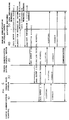
- Fig. 3A is a diagram showing an example of stored contents of a location register 50 in a mobile communication network
- Fig. 3B a diagram showing an example of stored contents of a storage part 22 of an indoor communication system control device 20.
- Fig. 4 is a diagram showing a location registration sequence in a first embodiment of this invention method.
- Fig. 5 is a diagram showing a location de-registration sequence in the first embodiment.
- Fig. 6 is a diagram showing a call terminating sequence in the first embodiment.
- Fig. 7 is a diagram showing a call originating sequence in the first embodiment.
- Fig. 8 is a diagram showing a location registration sequence in a second embodiment of this invention method.
- Fig. 9 is a diagram showing location re-registration sequence in the second embodiment.
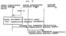
- Fig. 10 is a diagram showing an incoming call forwarding de-registration sequence in the second embodiment.
- Fig. 11 is a diagram showing a call terminating sequence in the second embodiment.
- Fig. 12 is a diagram showing a location registration sequence in a third embodiment of this invention method.
- Fig. 13 is a diagram showing a mobile location checking sequence in the third embodiment.
- Fig. 14 is a diagram showing an incoming call forwarding de-registration sequence in the third embodiment.
- Fig. 15 is a block diagram illustrating a system, including an ISDN network, which embodies this invention method and another embodiment of the device according to the present invention.
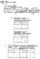
- Fig. 16A is a diagram showing an example of a numbering system including a sub-address other than a subscriber's number
- Fig. 16B a diagram showing an example of stored contents of a storage part 22 in Fig. 15
- Fig. 16C a diagram showing an example of stored contents of a location register 50 in Fig. 15.
- Fig. 17 is a diagram showing a location registration sequence in the system depicted in Fig. 15.
- a location register 50 provided in a mobile communication switching center 40 of a mobile communication system 80 as shown in Fig. 2 there are stored for each mobile communication terminal, for example, the zone where it currently stays (location registration area information) and an incoming call forwarding destination address when it is registered.
- the mobile communication switching center 40 is connected to an indoor communication system 70 via the public fixed communication network in the afore-mentioned example, though not shown in Fig. 2.
- the indoor communication system 70 is provided with an indoor communication control device 20 which is connected to the mobile communication switching center 40 and an indoor base station 30 which is connected both of the indoor communication system control device 20 and the mobile communication terminal 10.
- a plurality of indoor base stations 30 may also be connected to the indoor communication system control device 20 as shown in Fig. 1A. Moreover, the indoor communication system control device 20 and the mobile communication switching center 40 may also be interconnected via the public network 2 as shown in Fig. 1A. The communication system control device 20 and the indoor base station 30 may sometimes be formed as a unitary structure.
- the indoor communication system control device 20 has, in addition to means including the PBX in Fig. 1A which effects control necessary for communications between mobile communication terminals belonging to the indoor communication system 70 or between them and communication terminals of the public fixed communication network 2 or mobile communication network 1: destination address assignment means 21 which assigns a destination address, i.e. one of subscriber's numbers of the indoor communication system 70 in this example, to the mobile communication terminal 10 which has made a request for registration that it is staying in the service area of the indoor communication system 70; destination address-communication terminal correspondence storage means 23 which stores the correspondence between the destination address and the number of the mobile communication terminal assigned it, as shown in Fig.
- destination address assignment means 21 which assigns a destination address, i.e. one of subscriber's numbers of the indoor communication system 70 in this example, to the mobile communication terminal 10 which has made a request for registration that it is staying in the service area of the indoor communication system 70
- destination address-communication terminal correspondence storage means 23 which stores the correspondence between the destination address and the number of the mobile communication terminal assigned it
- destination address acknowledge means 24 which requests a mobile communication system 80 to register the destination address assigned to the mobile communication terminal 10 as its visited zone in the location register 50; and erase means 25 which, upon receiving a location de-registration request from the mobile communication switching center 40, erases the number of the mobile communication terminal and the destination address assigned thereto, contained in the request, from a storage part 20 or rewrites the destination address to information which indicates that the mobile communication terminal 10 is not in the service area of the indoor communication system.
- Fig. 4 there is shown processing necessary for the mobile communication terminal 10 to stay under the command of the indoor communication system 70 in a first embodiment of this invention method.
- the indoor base station 30 always emit an indoor communication system identifying signal by radio.
- the indoor communication system identifying signal may contain an area identifier of the indoor communication system.
- the mobile communication terminal 10 Upon receiving the indoor communication system identifying signal, the mobile communication terminal 10 sends to the indoor base station 30 a location registration request signal containing the number of the mobile communication terminal 10.
- the indoor base station 30 relays the location registration request signal to the indoor communication system control device 20.
- the indoor communication system control device 20 Upon receiving the location registration request signal, the indoor communication system control device 20 sends a location registration acknowledgement signal to the indoor base station if the number of the mobile communication terminal 10 has already been stored in the storage part 22, that is, if a destination address has already been assigned to the mobile communication terminal.
- the indoor communication system control device 20 assigns one of subscriber's numbers of the indoor communication system 70 (a destination address) to the mobile communication terminal 10, stores the relationship between the number of the mobile communication terminal 10 and the destination address in the storage part 22, sends to the mobile communication switching center 40 a location registration request signal containing the number of the mobile communication terminal 10 and the destination address assigned thereto, and sends a location registration acknowledgement signal to the indoor base station 30.
- the indoor communication system 70 and the mobile communication network 80 are interconnected via the public network 2 as shown in Fig. 1, a telephone number that identifies the indoor communication system 70 is used as the destination address.
- the indoor base station 30 relays the above-mentioned location registration acknowledgement signal to the mobile communication terminal 10.
- the mobile communication switching center 40 stores the above-said destination address as location registration area information (visited zone information) for the number of the mobile communication terminal 10 in the location register 50.
- Fig. 5 there is shown a sequence of processes that are performed when the mobile communication terminal 10 moves out of the coverage of the indoor communication system 70.
- the location register 50 judges it from the destination address number and sends to the mobile communication switching center 40 a location registration erase request signal containing the number of the mobile communication terminal 10.
- the mobile communication switching center 40 relays the location registration erase request signal to the indoor communication control device 20.
- the indoor communication system control device 20 erases the information of the mobile communication terminal 10 stored in the storage part 22 so as to cancel the assignment of the destination address to the mobile communication terminal 10.
- Fig. 6 there is shown a sequence of steps for connecting a terminating call to the mobile communication terminal 10 in the service area of the indoor communication system 70.
- the mobile communication switching center 40 Having received directly from a call originating terminal or via the mobile communication network 1 a call setup signal containing the number of the mobile communication terminal 10, the mobile communication switching center 40 reads out of the location register 50 information necessary for receiving a call which contains the destination address of the mobile communication terminal 10, and sends a call setup signal containing the destination address to the indoor communication system control device 20.
- the indoor communication system control device 20 Upon receiving the call setup signal, the indoor communication system control device 20 reads out of the storage part 22 the number of the mobile communication terminal 10 corresponding to the destination address and, based on the information thus read out, sends a call setup signal to the indoor base station 30.
- the indoor base station 30 relays the call setup signal to the mobile communication terminal 10.
- the mobile communication terminal 10 responds to the call setup signal to send an alerting signal to the indoor communication system control device 20 and, if a user answers, sends a connect signal, and the indoor base station 30, the indoor communication system control device 20 and the mobile communication switching center 40 relay the alerting signal and the connect signal to the call originating terminal, enabling communication.
- the indoor base station indicating the service area of the indoor base station 30 of the indoor communication system 70 where the mobile communication terminal 10 currently stays is prestored in the storage part 22 in correspondence with the number of the mobile communication terminal as depicted in Fig. 3B.
- alerting is carried out, for example, only a certain story (floor) of a building via the stored indoor base station 30; it is also possible, in this case, to perform simultaneous alerting via all the indoor base stations 30 in the indoor communication system 70 or for each group of indoor base stations 30.
- Fig. 7 shows a sequence of steps involved in originating a call from the mobile communication terminal 10 staying in the service area of the indoor communication system 70.
- the mobile communication terminal 10 sends to the indoor base station 30 a call setup signal including a destination terminal number.
- the indoor base station 30 and the indoor communication system control device 20 relay the call setup signal to the mobile communication switching center 40.
- the mobile communication switching center 40 connects the call setup signal to the party specified by the destination terminal number and relays an alerting signal and a connect signal from the specified party to the indoor communication system control device 20.
- the indoor communication system control device 20 and the indoor base station 30 relay the alerting signal and the connect signal to the mobile communication terminal 10, which starts communication upon receiving the answer signal.
- the indoor communication system 70 may also be adapted so that when receiving a location registration erase request signal, it stores in the storage part 22 information indicating that the mobile communication terminal 10 is not in its coverage.
- the system configuration of the second embodiment is the same as that of the first embodiment, but the location register 50 stores an incoming call forwarding destination address of the mobile communication terminal 10 and the communication system control device 20 and the mobile communication terminal 10 have a timer 91 and a timer 92, respectively.
- Fig. 8 shows a sequence of steps involved in the case where the mobile communication terminal 10 is in the coverage of the indoor communication system 70.
- the indoor base station 30 always emits an indoor communication system identifying signal by radio.
- the mobile communication terminal 10 Upon receiving the indoor communication system identifying signal, the mobile communication terminal 10 sends to the indoor base station 30 a location registration request signal including the number of the mobile communication terminal 10.
- the indoor base station 30 relays the location registration request signal to the indoor communication system control device 20.
- the indoor communication system control device 20 checks information about the mobile communication terminal 10 and, if the information is not prestored in the storage part 22, assigns a destination address to the mobile communication terminal 10, after which the control device sends to the mobile communication switching center 40 an incoming call forwarding registration signal including the number of the mobile communication terminal 10 and the destination address assigned thereto, sends a location registration acknowledgement signal to the indoor base station 30, and sets the timer 91.
- the indoor base station 30 relays the location registration acknowledgement signal to the mobile communication terminal 10.
- the mobile communication terminal 10 sets the timer 92. In this instance, the time T2 that is set in the timer 92 is selected shorter than the time T1 to be set in the timer 91.
- the mobile communication switching center 40 stores in the location register 50 the destination address as the incoming call forwarding destination address corresponding to the number of the mobile communication terminal 10.
- Fig. 9 shows a sequence of steps involved in the re-registration of the location of the mobile communication terminal 10 in the indoor communication system 70.
- the mobile communication terminal 10 sends again a location registration request signal to the indoor base station 30.
- the indoor base station 30 relays the location registration request signal to the indoor communication system control device 20.
- the indoor communication system control device 20 checks information (the terminal number) of the mobile communication terminal 10 and, if it is prestored in the storage part 22, the indoor communication system control device 20 stops the timer 91, then sends a location registration acknowledgement signal to the indoor base station 30 and sets the timer 91 again.
- the indoor base station 30 relays the location registration acknowledgement signal to the mobile communication terminal 10. Thereafter, the mobile communication terminal 10 sends a location registration request signal at intervals of the time T2 which is set by the timer 92.
- Fig. 10 shows a sequence of steps which are performed when the mobile communication terminal 10 has moved out of the coverage of the indoor communication system 70.
- the location registration request signal does not reach the indoor communication system control device 20.
- the indoor communication system control device 20 cancels the assignment of the destination address to the mobile communication terminal 10, then erases the terminal number of the mobile communication terminal 10 and the destination address assigned thereto in the storage part 22, or writes information that the terminal number is not in the coverage of the indoor communication system, and sends to the mobile communication switching center 40 an incoming call forwarding de-registration signal including the number of the mobile communication terminal 10.
- the mobile communication switching center 40 erases the incoming call forwarding destination address of the mobile communication terminal 10 stored in the location register 50.
- Fig. 11 shows a sequence of steps involved in connecting an incoming call to the mobile communication terminal 10 staying in the coverage of the indoor communication system 70.
- the mobile communication switching center 40 Upon receiving from another terminal or public fixed communication network 2 a call setup signal including the number of the mobile communication terminal 10, the mobile communication switching center 40 reads out the location registered area information (the visited zone) of the mobile communication terminal 10 from the location register 50, then calls the mobile communication terminal 10 via the base station 4 (Fig. 1) of the specified location registered area 60 and, if no answer is received, reads out the incoming call forwarding destination address of the mobile communication terminal 10 from the location register 50 and sends to the indoor communication system control device 20 a call setup signal including the incoming call forwarding destination address.
- the indoor communication system control device 20 Upon receiving the call setup signal, the indoor communication system control device 20 reads out of the storage part 22 the number of the mobile communication terminal 10 corresponding to the above-mentioned incoming call forwarding destination address and, based on the information thus read out, sends a call setup signal to the indoor base station 30.
- the indoor base station 30 relays the call setup signal to the mobile communication terminal 10.
- the mobile communication terminal 10 Upon receiving the call setup signal, the mobile communication terminal 10 sends an alerting signal to the indoor communication system control device 20 and, if a user answers, sends a connect signal; the indoor base station 30, the indoor communication system control device 20 and the mobile communication switching center 40 relay the alerting signal and the connect signal to the call originating terminal, starting communication.
- the call setup processing in this second embodiment is performed in the same manner as in the first embodiment.
- the system configuration of the third embodiment is the same as that of the first embodiment, but the location register 50 stores the incoming call forwarding destination address of the mobile communication terminal 10 and the communication system control device 20 has two timers 91 and 93.
- Fig. 12 shows a sequence of steps involving when the mobile communication terminal 10 is in the coverage of the indoor communication system 70.
- the indoor base station 30 always radiates a communication system identifying signal by radio.
- the mobile communication terminal 10 Upon receiving this communication system identifying signal, the mobile communication terminal 10 sends to the indoor base station 30 a location registration request signal including the number of the mobile communication terminal 10.
- the indoor base station 30 relays the location registration request signal to the indoor communication control device 20.
- the indoor communication system control device 20 Upon receipt of the location registration request signal, the indoor communication system control device 20 checks information about the mobile communication terminal 10 and, if the information is not found in the storage part 22, assigns a destination address to the mobile communication terminal 10; then, the control device stores the number of the mobile communication terminal 10 and the destination address assigned thereto, sends a location registration acknowledgement signal to the indoor base station 30 and, at the same time, sends to the mobile communication switching center 40 an incoming call forwarding registration signal including the number of the mobile communication terminal 10 and the destination address, and sets the timer 91. The indoor base station 30 relays the location registration acknowledgement signal to the mobile communication terminal 10.
- the mobile communication switching center 40 Upon receiving the incoming call forwarding registration signal, the mobile communication switching center 40 stores the destination address as the incoming call forwarding destination address corresponding to the number of the mobile communication terminal 10 in the location register 50. This processing is identical with that of Fig. 8, except that the setting of the timer 92 in the mobile communication terminal 10 is omitted in Fig. 8.
- Fig. 13 shows a sequence of steps involved in the confirmation of the location of the mobile communication terminal 10 in the coverage of the indoor communication system 70.
- the indoor communication system control device 20 sends a mobile location confirmation request signal to the indoor base station 30 and sets the timer 93.
- the mobile location confirmation request signal is a signal to make sure that the mobile communication terminal 10 is in the coverage of the indoor communication system, or a pseudo-alerting signal to the mobile communication terminal 10.
- the indoor base station 30 relays the mobile location confirmation request signal to the mobile communication terminal 10.
- the mobile communication terminal 10 Upon receipt of the mobile location confirmation request signal, the mobile communication terminal 10 sends a mobile location confirmation connect signal to the indoor base station 30.
- the indoor base station 30 relays the mobile location confirmation connect signal to the indoor communication system control device 20.
- the indoor communication system control device 20 stops the timer 93 and resets the timer 91. Thereafter, the indoor communication system control device 20 confirms the mobile location at intervals of the time T1 set by the timer 91.
- the mobile location confirmation connect signal is a signal indicating that the mobile communication terminal 10 is in the coverage of the indoor communication system, or an answer signal from the mobile communication terminal 10.
- Fig. 14 shows a sequence of steps involved when the mobile communication terminal 10 has left the coverage of the indoor communication system 70.
- the indoor communication system control device 20 Upon each passage of the time T1 set by the timer 91, that is, upon each time out of the timer 91, the indoor communication system control device 20 sends a mobile location confirmation request signal to the indoor base station 30 and resets the timer 93.
- the indoor base station 30 sends out the mobile location confirmation request signal so as to relay it to the mobile communication terminal 10.
- the mobile location confirmation request signal does not reach the mobile communication terminal 10, which does not deliver the mobile location confirmation connect signal.
- the indoor communication control device 20 cancels the assignment of the destination address to the mobile communication terminal 10, erases information about the mobile communication terminal 10 in the storage part 22, or rewrites the information to one that indicates that the mobile communication terminal is out of the coverage of the indoor communication system, and sends to the mobile communication switching center 40 an incoming call forwarding de-registration signal including the number of the mobile communication terminal 10.
- the mobile communication switching center 40 erases the incoming call forwarding destination address of the mobile communication terminal 10 stored in the location register 50.
- the indoor communication control device does not send the incoming call forwarding de-registration signal but instead delivers the mobile location confirmation request signal once to several times and, if no mobile location confirmation answer is received thereto, sends out the incoming call forwarding de-registration signal.
- the communication network to which the second communication system is directly connected constitutes a digital communication network of a numbering system composed of a subscriber's number and a sub-address
- the afore-mentioned destination address can be replaced with the sub-address.
- the second communication system (the indoor communication system in this example) 70 is connected directly to a public ISDN network (a digital integrated communication network) 100, that is, the indoor communication system 70 is a subscriber of the public ISDN network 100.
- the public ISDN network 100 is connected to the mobile communication network 1.
- the public ISDN network 100 two communications can simultaneously be made per subscriber line, that is, per subscriber's number, and it is possible to connect a plurality of terminals to one subscriber's line and reach them via the subscriber's line by distinguishing them through the use of the sub-addresses. That is, as shown in Fig. 16A, the numbering system of the public ISDN network 100 is formed by 55 digits, 15 digits of which form an ISDN subscriber's number 101 and the remaining 40 digits form an ISDN sub-address 102. The subscriber's number 101 is used to reach the subscriber concerned and the sub-address 102 is used to reach any one of its terminals.
- the mobile communication terminal 10 can be admitted into the coverage of the indoor communication system 70 by performing substantially the same processing as shown in Fig. 12, for example. This will be described in brief.
- the communication system control device 20 having received the location registration request assigns the sub-address to the mobile communication terminal 10 by sub-address assigning means 27 (Fig. 15), stores the relationship between the sub-address and the mobile communication terminal number in the storage part 22 by sub-address-communication terminal correspondence storing means 28 in such a manner as shown in Fig.
- the mobile communication switching center 40 then informs the mobile communication terminal 10 of the acceptance of the location registration, and sends to the mobile communication switching center 40 the subscriber's number of the indoor communication system and an incoming call forwarding registration request added with the above-mentioned sub-address and the communication terminal number.
- the mobile communication switching center 40 stores the subscriber's number and the sub-address as the incoming call forwarding destination address in the part corresponding to the number of the mobile communication terminal in the location register 50, for example, as shown in Fig. 16B.
- the communication system control device 20 sets the timer 91 and, when it times out, sends a mobile location confirmation request to the mobile communication terminal 10.
- the subsequent processing is carried out in the same manner as shown in Figs. 13 and 14, and if no answer is received to the mobile location confirmation request, the control device cancels the assignment of the sub-address to the mobile communication terminal 10 and sends an incoming call forwarding de-registration request to the mobile communication network 1.
- the cancellation of the assignment of the sub-address may be effected by erasing the relationship between the sub-address and the terminal number from the storage part 22 as described previously, or by storing that the terminal is not in the coverage of the indoor communication system.
- a call from another terminal to the mobile communication terminal 10 in the coverage of the indoor communication system 70 is processed by the same sequence of steps as shown in Fig. 11. That is, the mobile communication switching center 40 is caused to read out the visited zone of the called terminal from the location register 50 on the basis of the number of the called terminal, a request is made to the zone for calling the mobile communication terminal, and if no answer is received, the switching center is caused to read out the incoming call forwarding destination address of the number of the called terminal from the location register 50, or when the call forwarding destination address is prestored, the switching center is caused read out without making the call request to the zone, and a call setup request is made to the ISDN network 100 to connect the incoming call to the call forwarding destination address, that is, the ISDN subscriber's number and its sub-address.
- the indoor communication system control device 20 put by this call receiving request in the condition of terminating connection with the subscriber's number, uses the sub-address to read out the mobile communication terminal number from the storage part 22 and calls the mobile communication terminal of the read-out terminal number via the base station 30.
- two communications can simultaneously be performed over one subscriber's line as mentioned previously; for example, even if ten sub-addresses are assigned to different mobile communication terminals for one subscriber's number, there is no problem, if three or more of the ten mobile communication terminals do not often communicate at the same time. Moreover, since the assignment of the sub-address to the mobile communication terminal which has left the coverage of the indoor communication system 70 is cancelled, the sub-address can efficiently be used.
- a terminating call to the mobile communication terminal 10 in the coverage of the indoor communication system 70 is connected from the mobile communication switching center 40 to the public ISDN network on the basis of information read out of the location register 50 as referred to previously.
- the mobile communication switching center 40 generates a packet having a data part formed by a call control signal including the sub-address referred to in the location register 50 and an address part formed by the subscriber's number of the indoor communication system control device 20, and sends it to the indoor communication system control device 20 via the public ISDN network 100.
- the packet is taken apart by the indoor communication system control device 20, then the sub-address is used to read out the number of the called mobile communication terminal from the storage part 22, and a call is made for the mobile communication terminal as described previously.
- the mobile communication switching center 40 When the call is connected, the mobile communication switching center 40 generates a packet having its data part formed by a speech or facsimile signal to the mobile communication terminal 10 is generated as is the case with the above-said call control signal, the packet being sent to the indoor communication system control device 20.
- the packet is taken apart, then the sub-address is read out, and a data signal is set to a mobile communication terminal of the terminal number corresponding to the read-out sub-address.
- the processing for originating a call from the mobile communication terminal 10 in the coverage of the indoor communication system 70 is exactly the same as the processing depicted in Fig. 7.
- the cancellation of the sub-address assigned to the mobile communication terminal 10 is effected by the same processing as shown in Figs. 9 and 10. That is, the mobile communication terminal 10, which has moved into the coverage of the indoor communication system 70, makes a location registration request to the indoor communication system control device 20 at regular time intervals set by the timer 92, and the indoor communication system control device 20 responds to the location registration request to reset the timer 91, and when the timer 91 times out because no location registration request is received, the control device cancels the sub-address assigned to the mobile communication terminal and makes an incoming call forwarding de-registration request.
- the sub-address assignment is not limited specifically to the case of connecting an incoming call to the mobile communication terminal in the coverage of the second communication system by the incoming call forwarding registration; it is also possible to employ a system configuration in which, as is the case with the processing depicted in Fig. 4, the sub-address is assigned to the mobile communication terminal 10 having entered the coverage of the second communication system 70, a location registration request added with the terminal number, the sub-address and the subscriber's number is sent to the mobile communication switching center 40, and the subscriber's number and the sub-address are stored in the location register 50 as visited zone area information of the mobile communication terminal.
- the cancellation of the sub-address in this case is carried out in the same manner as shown in Fig. 5.
- the location register 50 when the location registration of the mobile communication terminal 10 is changed in the location register 50, the location register 50 sends a location registration erase request to the indoor communication system control device 20 via the mobile communication switching center 40, and upon receiving the location registration erase request, the indoor communication system control device 20 cancels the sub-address assignment to the mobile communication terminal.
- the sub-address assignment can be cancelled by the same method for cancelling the assignment of the destination address; hence, the cancellation of the both will be referred to simply as an address cancellation.
- a plurality of sub-addresses are assigned to different mobile communication terminals for one subscriber's address, but if there are a plurality of subscribers' numbers, a plurality of sub-addresses can also be assigned to mobile communication terminals for each subscriber's number. This will permit simultaneous communication of three or more mobile communication terminals via the indoor communication system 70. In this instance, the correspondence between the sub-address and the mobile communication terminal number is prestored for each subscriber's number in the storage part 22 as depicted in Fig. 16.
- the indoor communication system control device 20 Upon receiving a location registration request signal from the mobile communication terminal 10, the indoor communication system control device 20 assigns the destination address or sub-address as described previously; when there is no destination address or sub-address to assign, it is also possible to employ a method which sends a mobile location confirmation request signal to every mobile communication terminal 10, cancels the assignment of the destination address or sub-address to the mobile communication terminal having not answered the request signal, and assigns such a destination address or sub-address to the mobile communication terminal which has made the location registration request.
- the present invention has been described as being applied to the case where the mobile communication terminal is in the coverage of the indoor communication system, the invention is also applicable to the case where the mobile communication terminal 10 is in the service area of a cordless telephone as shown in Fig. 1B, in which case the base station 8 performs the function of the indoor communication system control device 20 in Fig. 2.
- the present invention is applied to the case where the second communication system belongs to a public mobile communication network as well as to the case where it belongs to the public fixed communication network.
- incoming call forwarding destination change means 26 which automatically performs the same processing as that for setting and cancelling the incoming call forwarding operation, may also be provided in the indoor communication system control device 20 as depicted in Fig. 2.
- the communication system control device 20 starts the incoming call forwarding destination change means to automatically register the setup and cancellation of the incoming call forwarding destination address in the location register 50.
- the cancellation of the destination address or sub-address of the mobile communication terminal in the second communication system through the use of a timer can be applied not only to the case of registering the call interminating address or sub-address as an incoming call forwarding destination address in the location register but also to the case of registering it in the location register for the registration of the mobile location as shown in Fig. 4.
- the same mobile communication terminal can be used in the mobile communication network as well as in the second communication system; moreover, the same number can be used to originate and receive calls, regardless of in which network the mobile communication terminal is staying. Furthermore, when the mobile communication terminal is used in the coverage of the second communication system, communication can be effected by weak radio waves; hence, the battery used wears long.
- a mobile communication terminal which is not pre-registered in the second communication system can be used in the second communication system, and since the destination address or sub-address is assigned to the mobile communication terminal only when it is in the coverage of the second communication system, the destination address or sub-address can efficiently be utilized.
- a closed communication in the second communication system by the use of the mobile communication terminal can be achieved at low cost through the use of only the line of the second communication system. Moreover, by connecting the second communication system to a fixed communication network, call can be originated at the fee of fixed communication, permitting low-cost communication.
Landscapes
- Engineering & Computer Science (AREA)
- Computer Networks & Wireless Communication (AREA)
- Signal Processing (AREA)
- Mobile Radio Communication Systems (AREA)
- Telephonic Communication Services (AREA)
Applications Claiming Priority (7)
| Application Number | Priority Date | Filing Date | Title |
|---|---|---|---|
| JP2655594 | 1994-02-24 | ||
| JP2655594 | 1994-02-24 | ||
| JP26555/94 | 1994-02-24 | ||
| JP19880594 | 1994-08-23 | ||
| JP19880594 | 1994-08-23 | ||
| JP198805/94 | 1994-08-23 | ||
| PCT/JP1995/000250 WO1995023491A1 (fr) | 1994-02-24 | 1995-02-22 | Procede de communication utilisant communement un poste d'abonne mobile et systeme de controleur de communications utilise a cet effet |
Publications (3)
| Publication Number | Publication Date |
|---|---|
| EP0696153A1 true EP0696153A1 (de) | 1996-02-07 |
| EP0696153A4 EP0696153A4 (de) | 1997-01-29 |
| EP0696153B1 EP0696153B1 (de) | 2005-11-16 |
Family
ID=26364360
Family Applications (1)
| Application Number | Title | Priority Date | Filing Date |
|---|---|---|---|
| EP95909952A Expired - Lifetime EP0696153B1 (de) | 1994-02-24 | 1995-02-22 | Kommunikationsverfahren mit allgemeiner benutzung eines mobilkommunikationsendgerätes und kommunikationssystemsteuereinrichtung dafür |
Country Status (6)
| Country | Link |
|---|---|
| EP (1) | EP0696153B1 (de) |
| KR (1) | KR0174077B1 (de) |
| CN (1) | CN1119057C (de) |
| CA (1) | CA2154751A1 (de) |
| DE (1) | DE69534611T2 (de) |
| WO (1) | WO1995023491A1 (de) |
Cited By (6)
| Publication number | Priority date | Publication date | Assignee | Title |
|---|---|---|---|---|
| WO1998024259A2 (en) * | 1996-11-26 | 1998-06-04 | Telefonaktiebolaget Lm Ericsson (Publ) | Routing number selection by the base station controller of a cellular telephone network |
| FR2806241A1 (fr) * | 2000-03-08 | 2001-09-14 | Sagem | Procede de gestion d'un reseau de radiotelephonie comportant une base de localisation de terminaux |
| EP1257136A3 (de) * | 1995-09-08 | 2003-01-02 | At&T Wireless Services, Inc. | Drahtloses zellulares System |
| KR100386091B1 (ko) * | 2001-06-07 | 2003-06-02 | 한국과학기술원 | 옥내/외로 이동하는 이용자를 위한 최적의 이동통신망접속 및 로밍 시스템 및 방법 |
| DE10229165A1 (de) * | 2002-06-28 | 2004-01-29 | Tenovis Gmbh & Co. Kg | Verfahren zum Anmelden eines drahtlosen Endgerätes bei einem Vermittlungssystem eines Funksystems sowie Vorrichtung mit einer Kontroll-Applikation |
| EP1670222A2 (de) * | 2004-12-08 | 2006-06-14 | NEC Corporation | Drahtloser Kopfhörer, Mobilkommunikationssystem, Verwaltungsserver und Verfahren zur Herstellung eines Anrufs von einem drahtlosen Kopfhörer |
Families Citing this family (9)
| Publication number | Priority date | Publication date | Assignee | Title |
|---|---|---|---|---|
| KR100361005B1 (ko) * | 2000-11-15 | 2002-11-21 | (주) 콘텔라 | 부호분할 다중접속 사설망 기지국의 이동 단말기 위치등록 방법 |
| KR100403732B1 (ko) * | 2001-09-07 | 2003-10-30 | 삼성전자주식회사 | 사설 무선 시스템의 공중망 위치등록 장치 및 방법 |
| KR100810248B1 (ko) * | 2001-10-16 | 2008-03-06 | 삼성전자주식회사 | 이동 통신 시스템에서 이동 통신 단말의 위치 정보 제공방법 |
| KR100513022B1 (ko) * | 2002-09-10 | 2005-09-05 | 삼성전자주식회사 | 무선 고속 데이터 시스템에서 공중망과 사설망의 데이터위치 저장기 공통 사용 방법 및 시스템 |
| JP4176655B2 (ja) * | 2004-02-24 | 2008-11-05 | 株式会社エヌ・ティ・ティ・ドコモ | アドレス動的割当てシステム、中継装置、及び、アドレス動的割当方法 |
| KR100725767B1 (ko) * | 2005-11-24 | 2007-06-08 | 삼성전자주식회사 | 다중인터페이스를 가진 통합 단말기의 위치등록을 위한장치 및 방법 |
| TWI363537B (en) * | 2007-07-27 | 2012-05-01 | Qubes Inc | Method for establishing network connection and mobile communication system thereof |
| KR101403812B1 (ko) * | 2008-12-30 | 2014-06-03 | 에릭슨 엘지 주식회사 | 서비스 제공 방법, 가입자 관리 방법 및 옥내용 기지국 |
| US9210260B2 (en) * | 2012-10-15 | 2015-12-08 | Qualcomm Incorporated | Controlling communications between a mobile device and a base station |
Citations (2)
| Publication number | Priority date | Publication date | Assignee | Title |
|---|---|---|---|---|
| US4980907A (en) * | 1989-12-15 | 1990-12-25 | Telefonaktiebolaget L M Ericsson | Telecommunication combination comprising a telepoint and a portable radio terminal |
| US5251248A (en) * | 1989-06-30 | 1993-10-05 | Nippon Telegraph And Telephone Corporation | Telephone network having personal numbers for position-independent |
Family Cites Families (1)
| Publication number | Priority date | Publication date | Assignee | Title |
|---|---|---|---|---|
| JPS5927636A (ja) * | 1982-08-06 | 1984-02-14 | Nec Corp | 無線通信方式 |
-
1995
- 1995-02-22 KR KR1019950703391A patent/KR0174077B1/ko not_active IP Right Cessation
- 1995-02-22 DE DE69534611T patent/DE69534611T2/de not_active Expired - Lifetime
- 1995-02-22 WO PCT/JP1995/000250 patent/WO1995023491A1/ja active IP Right Grant
- 1995-02-22 CA CA2154751A patent/CA2154751A1/en not_active Abandoned
- 1995-02-22 EP EP95909952A patent/EP0696153B1/de not_active Expired - Lifetime
- 1995-02-22 CN CN95190044A patent/CN1119057C/zh not_active Expired - Fee Related
Patent Citations (2)
| Publication number | Priority date | Publication date | Assignee | Title |
|---|---|---|---|---|
| US5251248A (en) * | 1989-06-30 | 1993-10-05 | Nippon Telegraph And Telephone Corporation | Telephone network having personal numbers for position-independent |
| US4980907A (en) * | 1989-12-15 | 1990-12-25 | Telefonaktiebolaget L M Ericsson | Telecommunication combination comprising a telepoint and a portable radio terminal |
Non-Patent Citations (1)
| Title |
|---|
| See also references of WO9523491A1 * |
Cited By (12)
| Publication number | Priority date | Publication date | Assignee | Title |
|---|---|---|---|---|
| EP1257136A3 (de) * | 1995-09-08 | 2003-01-02 | At&T Wireless Services, Inc. | Drahtloses zellulares System |
| EP1257137A3 (de) * | 1995-09-08 | 2003-01-02 | At&T Wireless Services, Inc. | Drahtloses zellulares System |
| WO1998024259A2 (en) * | 1996-11-26 | 1998-06-04 | Telefonaktiebolaget Lm Ericsson (Publ) | Routing number selection by the base station controller of a cellular telephone network |
| WO1998024259A3 (en) * | 1996-11-26 | 1998-09-11 | Ericsson Telefon Ab L M | Routing number selection by the base station controller of a cellular telephone network |
| US5978677A (en) * | 1996-11-26 | 1999-11-02 | Telefonaktiebolaget L M Ericsson (Publ) | Migration of routing number selection to the base station controller of a cellular telephone network |
| FR2806241A1 (fr) * | 2000-03-08 | 2001-09-14 | Sagem | Procede de gestion d'un reseau de radiotelephonie comportant une base de localisation de terminaux |
| KR100386091B1 (ko) * | 2001-06-07 | 2003-06-02 | 한국과학기술원 | 옥내/외로 이동하는 이용자를 위한 최적의 이동통신망접속 및 로밍 시스템 및 방법 |
| DE10229165A1 (de) * | 2002-06-28 | 2004-01-29 | Tenovis Gmbh & Co. Kg | Verfahren zum Anmelden eines drahtlosen Endgerätes bei einem Vermittlungssystem eines Funksystems sowie Vorrichtung mit einer Kontroll-Applikation |
| DE10229165B4 (de) * | 2002-06-28 | 2006-03-30 | Tenovis Gmbh & Co. Kg | Verfahren zum Anmelden eines drahtlosen Endgerätes bei einem Vermittlungssystem eines Funksystems sowie Vorrichtung mit einer Kontroll-Applikation |
| EP1670222A2 (de) * | 2004-12-08 | 2006-06-14 | NEC Corporation | Drahtloser Kopfhörer, Mobilkommunikationssystem, Verwaltungsserver und Verfahren zur Herstellung eines Anrufs von einem drahtlosen Kopfhörer |
| EP1670222A3 (de) * | 2004-12-08 | 2006-07-12 | NEC Corporation | Drahtloser Kopfhörer, Mobilkommunikationssystem, Verwaltungsserver und Verfahren zur Herstellung eines Anrufs von einem drahtlosen Kopfhörer |
| US7844220B2 (en) | 2004-12-08 | 2010-11-30 | Nec Corporation | Headset, portable communication system, and headset calling method |
Also Published As
| Publication number | Publication date |
|---|---|
| DE69534611T2 (de) | 2006-07-27 |
| KR960701524A (ko) | 1996-02-24 |
| CA2154751A1 (en) | 1995-08-31 |
| CN1122179A (zh) | 1996-05-08 |
| EP0696153A4 (de) | 1997-01-29 |
| WO1995023491A1 (fr) | 1995-08-31 |
| EP0696153B1 (de) | 2005-11-16 |
| CN1119057C (zh) | 2003-08-20 |
| DE69534611D1 (de) | 2005-12-22 |
| KR0174077B1 (ko) | 1999-04-01 |
Similar Documents
| Publication | Publication Date | Title |
|---|---|---|
| US4833702A (en) | Telephone registration and cancellation control in a wide area cordless telephone system | |
| US5920815A (en) | Personal phone number system | |
| KR930000798B1 (ko) | 트렁크된 통신 시스템 및 시스템 사이를 로움하는 방법 | |
| CA2078439C (en) | Apparatus and method for directing calls to mobile telephone subscribers | |
| EP0474812B1 (de) | System und verfahren zur dynamischen zuteilung von streifen leitweglenkungsnummern | |
| US6584095B1 (en) | Method and system for supporting wireless communications within an internetwork | |
| US4879740A (en) | Wide area cordless telephone system having means for avoiding double registrations | |
| EP0696153B1 (de) | Kommunikationsverfahren mit allgemeiner benutzung eines mobilkommunikationsendgerätes und kommunikationssystemsteuereinrichtung dafür | |
| JPH06509216A (ja) | 無線電話通信システム内の呼伝達サービス | |
| JPH08172673A (ja) | Phs着信制御装置 | |
| KR100282407B1 (ko) | 스위칭 시스템 및 스위칭 시스템에서의 안내방송 운용 방법 | |
| JPH08237727A (ja) | 携帯無線電話機のローミング登録・解除方法 | |
| JP2003018657A (ja) | 移動体通信システム及び装置及び制御方法 | |
| JPH07307979A (ja) | 構内交換システム | |
| JPH11122655A (ja) | 移動通信システム | |
| JPH0644787B2 (ja) | 着信転送登録情報の登録更新方式 | |
| US7336948B1 (en) | Communication terminal equipment for wireless communication with transmission/reception base stations of different communication systems | |
| KR0184176B1 (ko) | 자동 응답 서비스 방법 | |
| KR100208288B1 (ko) | 서치 도중 발신 중도 포기 호 처리 방법 | |
| JPH04287436A (ja) | 移動通信システム | |
| JP2990132B2 (ja) | 移動体通信システムにおける通信中着信処理方法 | |
| KR20010009947A (ko) | 통신 시스템에서 호 방향 전환 방법 | |
| KR19990031952A (ko) | 무선 채널 할당 실패 호의 스위치 점유 방지 방법 | |
| JPH0722423B2 (ja) | 移動無線通信方式 | |
| JPH02200023A (ja) | 移動通信における着信制御方法 |
Legal Events
| Date | Code | Title | Description |
|---|---|---|---|
| PUAI | Public reference made under article 153(3) epc to a published international application that has entered the european phase |
Free format text: ORIGINAL CODE: 0009012 |
|
| 17P | Request for examination filed |
Effective date: 19950718 |
|
| AK | Designated contracting states |
Kind code of ref document: A1 Designated state(s): DE FR GB IT SE |
|
| A4 | Supplementary search report drawn up and despatched | ||
| AK | Designated contracting states |
Kind code of ref document: A4 Designated state(s): DE FR GB IT SE |
|
| 17Q | First examination report despatched |
Effective date: 20010813 |
|
| GRAP | Despatch of communication of intention to grant a patent |
Free format text: ORIGINAL CODE: EPIDOSNIGR1 |
|
| GRAS | Grant fee paid |
Free format text: ORIGINAL CODE: EPIDOSNIGR3 |
|
| GRAA | (expected) grant |
Free format text: ORIGINAL CODE: 0009210 |
|
| AK | Designated contracting states |
Kind code of ref document: B1 Designated state(s): DE FR GB IT SE |
|
| REG | Reference to a national code |
Ref country code: GB Ref legal event code: FG4D |
|
| REF | Corresponds to: |
Ref document number: 69534611 Country of ref document: DE Date of ref document: 20051222 Kind code of ref document: P |
|
| REG | Reference to a national code |
Ref country code: SE Ref legal event code: TRGR |
|
| ET | Fr: translation filed | ||
| PLBE | No opposition filed within time limit |
Free format text: ORIGINAL CODE: 0009261 |
|
| STAA | Information on the status of an ep patent application or granted ep patent |
Free format text: STATUS: NO OPPOSITION FILED WITHIN TIME LIMIT |
|
| 26N | No opposition filed |
Effective date: 20060817 |
|
| PGFP | Annual fee paid to national office [announced via postgrant information from national office to epo] |
Ref country code: IT Payment date: 20120218 Year of fee payment: 18 |
|
| PGFP | Annual fee paid to national office [announced via postgrant information from national office to epo] |
Ref country code: FR Payment date: 20130301 Year of fee payment: 19 Ref country code: SE Payment date: 20130212 Year of fee payment: 19 Ref country code: GB Payment date: 20130220 Year of fee payment: 19 Ref country code: DE Payment date: 20130220 Year of fee payment: 19 |
|
| REG | Reference to a national code |
Ref country code: DE Ref legal event code: R119 Ref document number: 69534611 Country of ref document: DE |
|
| REG | Reference to a national code |
Ref country code: SE Ref legal event code: EUG |
|
| REG | Reference to a national code |
Ref country code: DE Ref legal event code: R079 Ref document number: 69534611 Country of ref document: DE Free format text: PREVIOUS MAIN CLASS: H04Q0007380000 Ipc: H04W0004000000 |
|
| GBPC | Gb: european patent ceased through non-payment of renewal fee |
Effective date: 20140222 |
|
| REG | Reference to a national code |
Ref country code: FR Ref legal event code: ST Effective date: 20141031 |
|
| REG | Reference to a national code |
Ref country code: DE Ref legal event code: R119 Ref document number: 69534611 Country of ref document: DE Effective date: 20140902 Ref country code: DE Ref legal event code: R079 Ref document number: 69534611 Country of ref document: DE Free format text: PREVIOUS MAIN CLASS: H04Q0007380000 Ipc: H04W0004000000 Effective date: 20141020 |
|
| PG25 | Lapsed in a contracting state [announced via postgrant information from national office to epo] |
Ref country code: SE Free format text: LAPSE BECAUSE OF NON-PAYMENT OF DUE FEES Effective date: 20140223 |
|
| PG25 | Lapsed in a contracting state [announced via postgrant information from national office to epo] |
Ref country code: DE Free format text: LAPSE BECAUSE OF NON-PAYMENT OF DUE FEES Effective date: 20140902 Ref country code: FR Free format text: LAPSE BECAUSE OF NON-PAYMENT OF DUE FEES Effective date: 20140228 Ref country code: GB Free format text: LAPSE BECAUSE OF NON-PAYMENT OF DUE FEES Effective date: 20140222 |
|
| PG25 | Lapsed in a contracting state [announced via postgrant information from national office to epo] |
Ref country code: IT Free format text: LAPSE BECAUSE OF NON-PAYMENT OF DUE FEES Effective date: 20140222 |