EP0695671B1 - Système d'air-bag avec sangle de retenue pour couvercle - Google Patents
Système d'air-bag avec sangle de retenue pour couvercle Download PDFInfo
- Publication number
- EP0695671B1 EP0695671B1 EP95305387A EP95305387A EP0695671B1 EP 0695671 B1 EP0695671 B1 EP 0695671B1 EP 95305387 A EP95305387 A EP 95305387A EP 95305387 A EP95305387 A EP 95305387A EP 0695671 B1 EP0695671 B1 EP 0695671B1
- Authority
- EP
- European Patent Office
- Prior art keywords
- cover
- airbag
- tether
- panel
- housing
- Prior art date
- Legal status (The legal status is an assumption and is not a legal conclusion. Google has not performed a legal analysis and makes no representation as to the accuracy of the status listed.)
- Expired - Lifetime
Links
Images


Classifications
-
- B—PERFORMING OPERATIONS; TRANSPORTING
- B60—VEHICLES IN GENERAL
- B60R—VEHICLES, VEHICLE FITTINGS, OR VEHICLE PARTS, NOT OTHERWISE PROVIDED FOR
- B60R21/00—Arrangements or fittings on vehicles for protecting or preventing injuries to occupants or pedestrians in case of accidents or other traffic risks
- B60R21/02—Occupant safety arrangements or fittings, e.g. crash pads
- B60R21/16—Inflatable occupant restraints or confinements designed to inflate upon impact or impending impact, e.g. air bags
- B60R21/20—Arrangements for storing inflatable members in their non-use or deflated condition; Arrangement or mounting of air bag modules or components
- B60R21/215—Arrangements for storing inflatable members in their non-use or deflated condition; Arrangement or mounting of air bag modules or components characterised by the covers for the inflatable member
- B60R21/216—Arrangements for storing inflatable members in their non-use or deflated condition; Arrangement or mounting of air bag modules or components characterised by the covers for the inflatable member comprising tether means for limitation of cover motion during deployment
Definitions
- the present invention relates to a serviceable, tethered cover, airbag system and more particularly to a motor vehicle airbag system employing a cover with a flexible tether detachably interconnected thereto to facilitate repair or replacement of the cover when desired.
- airbag cushioning devices used in motor vehicles, it is desirable to restrain and limit the amount of travel or movement of a cover or door away from a panel opening during airbag deployment.
- the cover or door normally closes an opening in a panel or a steering wheel. It is also desirable to prevent a cover or door from fracturing into pieces or fragments upon airbag deployment.
- an airbag cover commonly provides a portion of a panel or steering wheel surface in a passenger compartment of a vehicle, the cover can become defective, damaged or unsightly and it is desirable to replace or repair the cover without requiring disturbance of other components of the airbag system.
- U.S. Patent No. 3,822,894 to Muller et al. discloses a steering wheel having a built-in air cushion employing a strong hinge between a cover and a dish containing the airbag so that on inflation, the cover is pushed away but not completely liberated from attachment to the steering wheel.
- the Wulf et al. U.S. Patent No. 3,944,250, discloses an automatically inflatable gas cushion for the protection of passengers in vehicles employing a cover which is opened upon inflation of the airbag or gas cushion and which is retained by a flexible band so that the cover is restrained after opening.
- the Hirabayashi, U.S. Patent No. 4,911,471 discloses an arrangement of an airbag device in a motor vehicle wherein angular pivotal movement of a door over the airbag is restricted by a strap to limit the angular degree of opening when the airbag is inflated.
- U.S. Patent No. 4,964,653 to Parker discloses a self-skinned foam closure element for an inflatable restraint door assembly having a combination hinge and tether for restraining travel of the closure element during airbag deployment.
- U.S. Patent No. 5,064,217 to Shiracki discloses a cover for an airbag unit having "Nylon" yarn bands molded in place and wrapped around a retaining band of resin provided on the airbag enclosure or housing.
- U.S. Patent No. 5,150,919 to Sakakida et al. discloses an airbag system for a vehicle having a pair of doors or lids which pivotally open in opposite direction and which are restrained by belt members so that the lids pivot about transverse axes and open smoothly upon airbag deployment.
- U.S. Patent No. 5,195,776 to Sakakida et al. discloses an airbag installation having curved airbag cover lids which are reliably opened by rotation about a center point so as not to restrict the inflation of the airbag.
- U.S. Patent No. 5,072,967 to Batchelder et al. discloses an instrument panel having an invisible airbag deployment door with weakened sections formed therein but hidden from view for facilitating fracture of the door along predetermined lines for opening movement during airbag deployment.
- U.S. Patent No. 5,096,221 discloses an airbag door having plural substrates on the inside which normally retain the door in a closed position and at least one of which is notched or provided with a hidden tear seam to facilitate fracture for opening of the door.
- the Catron et al. U.S. Patent No. 5,211,421, discloses an airbag cover door retainer having bifurcated engagement flanges on the door normally retaining the door in a closed position and releasable to permit door opening during airbag deployment.
- the Fujiwara et al. United States Patent No. 5,199,739, discloses an airbag cover opening mechanism for a motor vehicle including a sheer pin which is severed upon opening pressure exerted on the inside of the door by the deploying airbag.
- U.S. Patent to Faigle et al. No. 5,242,191 discloses a tethered airbag cover system wherein the cover is retained after opening attached to the airbag itself.
- European Patent Application No. EPA-A-0415 362 discloses an airbag supporting system having two fly-away covers restrained by loose flexible straps.
- DE 38 43 686 A1 discloses an airbag cover for a car which is retained in one piece in relation to the dashboard of the automobile by a retaining hinge element.
- the present invention consists in a tethered cover assembly for use with a motor vehicle airbag system of the type wherein a panel is formed with an opening in the vicinity of a occupant's seat and a housing for an inflatable airbag is aligned with said opening to permit the airbag to pass through said opening when deployed, said assembly comprising:
- load spreading means is provided for attaching the tether to the cover so that the cover does not fracture or break apart during deployment of the airbag.
- the cover can be disconnected and reconnected to a tether with minimal disturbance of the airbag system so that replacement and repair of a damaged, defective or unsightly cover can be rapidly and easily accomplished.
- the present invention also provides an airbag system for motor vehicles and the like having a panel formed with an opening in the vicinity of an occupant's seat.
- An inflatable airbag is contained within a housing in a deflated condition and the housing is aligned with a panel opening to permit the airbag to pass outwardly when deployed to provide cushioning support for an occupant of the seat during an emergency.
- a tethered cover assembly as defined above is provided for normally closing the panel opening to protect the airbag.
- the flexible tether is detachably interconnected between the cover and the panel or the housing of the airbag assembly for positively limiting the distance of travel of the cover during airbag deployment.
- the detachable connector is preferably secured to the cover by a load spreading base or housing so that stress exerted by the tether on the cover during opening deployment of the airbag is spread over a relatively large area on the cover, thus reducing the possibility that the cover will fracture or break up, yet still positively retaining the cover a limited distance away from the panel opening.
- the detachable connector is operable to disconnect and reconnect a cover with the tether so that a damaged, defective or unsightly cover can be repaired and/or replaced with minimal disturbance of the components of the airbag system, and when the cover is detached servicing of the airbag components internally of the cover can be accomplished and thereafter the original cover or a replacement can be readily reattached to the tether and positioned in place to close the panel opening.
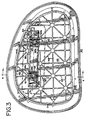
- FIGS. 1-4 a motor vehicle 20 having a passenger compartment 22 for accommodating a person 24 in seated position on a vehicle seat 26.
- the vehicle 20 forward of the occupant 24, the vehicle 20 includes a dashboard 28 and a panel 30 having an enlarged opening 32 spaced directly above an airbag and inflator assembly generally indicated by the reference numeral 34.
- the airbag and inflator assembly 34 includes a housing or canister 36 fixedly mounted in place beneath the panel 30 and the opening 32.
- An airbag 38 in deflated condition is stored and contained within the housing 36 until deployed as illustrated in FIG. 2 to protect the vehicle occupant 24 from injury in an accident.
- the panel opening 32 is normally closed by a movable cover 40, which as shown in FIGS. 1 and 4 forms part of the upper surface of the panel 30 above the opening 32.
- a movable cover 40 which as shown in FIGS. 1 and 4 forms part of the upper surface of the panel 30 above the opening 32.
- the cover 40 includes an outer skin 44 formed of molded resinous plastic material and an inner skin 46 also formed of relatively thick resinous plastic material to provide strength and integrity for the cover 40 overall so that break up or fracture of the cover into pieces does not occur upon airbag deployment.
- a number of integral ribs 48 are molded into the inner skin 46 for stiffening purposes and a layer of foam 50 is bonded between the inner and outer skins 46 and 44, respectively, of the cover 40 to provide a strong and lightweight body.
- the cover 40 is retained in a closed position (FIG. 1) directly above and over the opening 32 by a plurality of pins or spring latch elements 52 which are locked into openings 54 (FIG. 4) provided in a lower flange 30a of the panel 30, around the edge of the opening 32.
- the cover 40 acts as an integrated part of the panel 30 and at the same time protects the airbag assembly 34 from damage and limits access thereto.
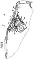
- one or more tethers of strong, flexible material such as a stranded metal cable 60, "Nylon” webbing, seat belt type material or the like is interconnected between the underside of the cover 40 and either the housing or canister 36 of the airbag inflator assembly 34 or, as schematically shown, the underside of panel 30.
- Inner ends of the flexible cable tethers 60 are interconnected to the upper sidewall of the housing or canister 36 by means of metal or plastic clips 62 (FIGS. 4 and 6).
- each cable tether 60 is provided with a swaged on, cylindrical cross-pin 61 of short length adapted to be detachably interconnected to a clevis type, connector 65 having a relatively large base 65a of square or rectangular shape secured to the lower face of the stiffening bar 66 with appropriate fasteners such as headed rivets or bolts (not shown) extended through aligned holes 63 in the base 65a and the bar 66.
- the clevis type connectors 65 include a pair of spaced apart, parallel, integrally formed, depending flanges 65b and 65c of generally triangular shape as best shown in FIGS. 5 and 6.
- Each flange 65b and 65c is formed with a circular opening 67 adjacent the central portion thereof having a diameter slightly larger than that of the cross-pin 61 on the cable tether 60.
- the openings 67 in each pair of facing flanges 65b and 65c are in coaxial alignment to provide bearing support surfaces for opposite end portions of the cross-pins 61 when inserted in place as shown in FIG. 6.
- each connector 65 is preferably formed of strong lightweight metal in a casting operation and inside faces of the flanges are spaced apart by a distance slightly greater than the diameter of the cable tether 60 to accommodate the cable between the flanges when interconnected as shown in FIG. 6.
- the flange 65b is formed with a slot 69 having an open mouth at the outer end on the edge of the flange.
- the open mouth of the slot 69 is wide enough to accommodate the diameter of the cable tether 60 when the tether is inserted into the slot from outside the flange and moved in a direction coaxial with the cross-pin along the centerline 71 of the circular openings 67.
- each slot 69 opens into the circular opening 67 of the flange 65b and once a cable tether 60 is inserted into the space between the flanges 65b and 65c, the cable tether is rotated downwardly to the position of FIG. 6 about the axis 71 so that the facing inside surfaces of the flanges 65b and 65c retain the cross-pins 61 from axial movement with opposite ends of cross-pin journalled in the cylindrical opening 67 of the flanges.
- the connectors 65 are attached to the stiffener bar 66 with the open mouth of the slots 69 facing toward the passenger or occupant 24 and the cable tethers 60 extend in an opposite direction toward the forward end of the vehicle as shown in FIGS. 1, 2 and 4.
- the cover 40 is withdrawn upwardly from the opening 32 in the panel 30 to expose the flanges 65b and 65c of the connectors 65 which project downwardly through slots 64a provided in the bottom wall of the compartment 64 formed in the inner skin or wall 46 of the cover 40.
- the cable tethers 60 are rotated in a counterclockwise direction (FIG. 4) until aligned with the slots 69 in the flanges 65a and the cables and cross-pins 61 are displaced along the axis 71 until free and clear of the flanges 65b and 65c, at which time a disconnection between the cover 40 and the cable tethers 60 is completed.
- the formed housing 64 in the inner skin 46 of the cover is provided with the slots 64a in the bottom wall at appropriate intervals along the length thereof to accommodate the number of connectors 65 and cable tethers 60 that are used in a particular system.
- the force exerted by the cable tethers 60 while in a taut condition (FIG. 2) is spread from the bases 65a of the connectors 65 to the stiffening bar 66 which are over a substantial portion of the length of the cover 40.
- This attachment arrangement greatly reduces the stress exerted by each cable tether 60 on the cover 40 during deployment of the airbag 38 and normally prevents fracture of the cover 40 into pieces or fragments which could become projectiles causing damage or injury.
- the number of cable tethers 60 required for a particular panel 60 may be increased if needed.
- 40 three rather than two tethers may be provided or the number of tethers may be decreased to one in some instances.
- the bases 65a of the connector 65 transmit and spread the load to the stiffening bar 66 which is positively contained between the inside wall or skin 46 and the outside wall or skin 44 in the foam 50 of cover 40.
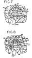
- the detachable connector 65A for use with a tether 60A formed of flexible webbing of "Nylon" plastic stranded material.
- the detachable connector 65A includes a generally rectangular metal or plastic housing 75 of hollow tubular cross-section having rectangular openings 75a and 75b at opposite ends sized to accommodate a middle section 77 of an elongated metal tongue 78 having deflectable fingers 79 at the outer end portion. When the fingers 79 are pinched together toward a central slot 80 they can pass through the openings 75a and 75b of the housing.
- the tongue 78 has an enlarged collar portion 81 which acts as a stop to limit further insertion of the tongue into the housing and which is permanently attached to the tether 60A which is looped through a slot therein.
- Outer, oppositely facing edges of the fingers 79 of the tongue 78 act as cam surfaces which engage opposite edges of the entrance opening 75a of the housing 75 as the tongue is initially inserted to cam the fingers together toward the central slot 80.
- inner stop portions 79a at the base of each finger 79 engage the housing 75 outside the end of the opening 75b to lock the tongue 78 in place in the housing and thus securely connect the tether 60A to the cover 40 in a detachable connection.
- the fingers 79 are pinched together toward the center slot 80 while a pulling force is exerted on the tether 60A to withdraw the tongue 78 from the housing 75.
- the housings 75 are permanently attached to the stiffening bar 66 and the bottom wall of the housing 64 by means of fasteners such as rivets or bolts (not shown) which pass through aligned openings in the stiffening bar, housing wall and bottom wall of the connector housing 75.
- the connector 65B includes a generally rectangular, metal or plastic housing 85 of hollow tubular, generally rectangular cross-section having a rectangular entrance opening 85a at one end sized to accommodate a middle section 87 of a tongue 88.
- the tongue 88 is generally similar both in structure and function to the tongue 78 of the prior embodiment except that an outer free end 89 of the tongue does not project outside of the housing 85 which is closed by an end wall 85b opposite the entrance opening 85a.
- the outer end portion of the tongue 88 is formed with a central slot 90 forming deflectable fingers 91 which are pinched toward the slot 90 by facing inside, opposite side edge walls 85c of the rectangular housing 85 as the tongue is inserted.
- the opposite side edge walls 85c have open slots 92 at their ends adjacent the housing end wall 85b, in order to accommodate rounded outer cam elements 93 on the outer edge of the fingers 91 which extend into the slots 92 to lock and hold the tongue 88 in place in a detachable connection within the housing 85.
- the rounded cam elements 93 are pinched toward the center slot 90 while a pull out force is exerted on the tongue from the tether 60B. As this occurs, the cam elements 93 on the fingers 91 pass along the inside surfaces of the opposite side edge walls 85c of the housing 85 until the tongue 88 is clear.
- Insertion of the tongue 88 to interconnect or reconnect the tether 60B and the cover 40 is accomplished simply by inserting and pushing the tongue 88 inwardly into the housing 85 through the entrance opening 85a until the cam elements 93 reach the side edge wall slots 92 permitting the fingers 91 to spring apart to lock the tongue in place.
Landscapes
- Engineering & Computer Science (AREA)
- Mechanical Engineering (AREA)
- Air Bags (AREA)
Claims (8)
- Ensemble couvercle retenu par une attache, pour utilisation avec un système d'airbag de véhicule automobile du type dans lequel un panneau comporte une ouverture au voisinage du siège d'un occupant et un logement pour airbag gonflable est aligné avec ladite ouverture pour permettre à l'airbag de passer par ladite ouverture lorsqu'il est déployé, ledit ensemble comprenant :un couvercle (40) dimensionné pour fermer une ouverture (32) dans un panneau du véhicule (30) pour protéger un airbag (38) et mobile pour découvrir ladite ouverture pendant le déploiement de l'airbag;une attache flexible, comprenant un élément flexible allongé (60, 60A, 60B) pour relier de manière amovible ledit couvercle et au moins ledit panneau ou ledit logement pour limiter le mouvement d'éloignement dudit couvercle par rapport au panneau pendant le déploiement;un moyen (62) pour fixer une extrémité de l'attache au panneau et/ou au logement; etun moyen de fixation (61, 65, 75, 78, 85, 88) reliant l'attache au couvercle pour limiter le mouvement d'éloignement du couvercle par rapport au panneau et au logement lors du déploiement de l'airbag,
caractérisé en ce que ledit moyen de fixation peut être libéré pour permettre le désaccouplement et le réaccouplement du couvercle et de l'attache, et comprend des raccords mâle et femelle inter-engageables de manière amovible, ledit raccord mâle (61, 78, 88) pouvant coulisser longitudinalement dans ledit raccord femelle (65, 75, 85) jusqu'à une position à laquelle il s'engage avec ledit raccord femelle, l'un desdits raccords (61, 78, 88) étant fixé à demeure audit moyen d'attache et l'autre desdits éléments (65, 75, 85) étant fixé à demeure audit moyen de couvercle. - Ensemble couvercle retenu par une attache selon la revendication 1, dans lequel ladite attache (60A, 60B) comprend une sangle de matériau tissé ayant une partie d'extrémité bouclée autour de l'un desdits raccords.
- Ensemble couvercle retenu par une attache selon la revendication 2, dans lequel ladite partie d'extrémité de ladite attache (60A, 60B) est bouclée autour dudit raccord mâle (78, 88).
- Ensemble couvercle retenu par une attache selon la revendication 1, dans lequel ladite attache (60) comprend un câble constitué de plusieurs torons.
- Ensemble couvercle retenu par une attache selon l'une quelconque des revendications précédentes, dans lequel ledit raccord mâle (78, 88) comprend plusieurs doigts allongés opposés espacés (79, 91) ayant des extrémités extérieures libres, au moins une extrémité extérieure libre d'un doigt pouvant fléchir latéralement vers un doigt opposé, ledit raccord mâle, lorsqu'il est ainsi fléchi, pouvant coulisser dans le sens longitudinal desdits doigts pour s'adapter dans ledit raccord femelle (75, 85) afin de relier ladite attache (60A, 60B) et ledit couvercle (40).
- Ensemble couvercle retenu par une attache selon la revendication 5, dans lequel au moins l'un desdits doigts allongés (79, 91) a un moyen de came (79a, 93) adjacent à ladite extrémité extérieure libre pour fixer ledit doigt et l'empêcher de se retirer dudit raccord femelle (75, 85) dans la direction longitudinale après libération de ladite flexion latérale.
- Ensemble couvercle retenu par une attache selon l'une quelconque des revendications précédentes, dans lequel le raccord (65, 75, 85) sur le couvercle (40) est monté sur une base (65a) ou un logement (75, 85) qui est lui-même fixé au couvercle (40), ladite base ou ledit logement étant dimensionné pour répartir sur une plus grande superficie du couvercle les contraintes résultant de la traction de l'attache (60) ou du couvercle lorsque le couvercle est écarté du panneau par le déploiement de l'airbag.
- Système d'airbag (34) pour véhicules automobiles (20) et similaires, ayant un panneau (30) comportant une ouverture (32) au voisinage du siège d'un occupant (26), et comprenant un airbag gonflable (38) et un logement (36) pour retenir ledit airbag pendant qu'il est à l'état dégonflé, ledit logement ayant une extrémité ouverte alignée avec ladite ouverture du panneau pour permettre audit airbag de passer à l'extérieur lorsqu'il est déployé pour offrir un support amortisseur à un occupant (24) dudit siège, le système comprenant en outre un ensemble couvercle retenu par une attache selon l'une quelconque des revendications précédentes, le couvercle (40) fermant ladite ouverture du panneau et l'attache flexible (60) reliant ledit couvercle et au moins ledit panneau ou ledit logement pour limiter le mouvement d'éloignement dudit couvercle par rapport audit panneau pendant le déploiement dudit airbag.
Applications Claiming Priority (2)
| Application Number | Priority Date | Filing Date | Title |
|---|---|---|---|
| US08/286,795 US6053527A (en) | 1994-08-05 | 1994-08-05 | Airbag system with serviceable tethered cover |
| US286795 | 1994-08-05 |
Publications (2)
| Publication Number | Publication Date |
|---|---|
| EP0695671A1 EP0695671A1 (fr) | 1996-02-07 |
| EP0695671B1 true EP0695671B1 (fr) | 1998-11-11 |
Family
ID=23100189
Family Applications (1)
| Application Number | Title | Priority Date | Filing Date |
|---|---|---|---|
| EP95305387A Expired - Lifetime EP0695671B1 (fr) | 1994-08-05 | 1995-08-01 | Système d'air-bag avec sangle de retenue pour couvercle |
Country Status (4)
| Country | Link |
|---|---|
| US (1) | US6053527A (fr) |
| EP (1) | EP0695671B1 (fr) |
| JP (1) | JP3021131U (fr) |
| DE (1) | DE69505909T2 (fr) |
Families Citing this family (40)
| Publication number | Priority date | Publication date | Assignee | Title |
|---|---|---|---|---|
| DE69729178T3 (de) * | 1996-11-07 | 2009-09-24 | Toyota Jidosha Kabushiki Kaisha, Toyota-shi | Anordnung und konstruktion einer kraftfahrzeug/insassenschutzvorrichtung |
| GB2324509A (en) * | 1997-04-24 | 1998-10-28 | Rover Group | Vehicle airbag housing assembly |
| DE19828163A1 (de) * | 1998-06-24 | 1999-12-30 | Volkswagen Ag | Rückhalteeinrichtung für ein eine Airbaganordnung abdeckendes Verkleidungsteil |
| US6149187A (en) * | 1999-05-24 | 2000-11-21 | Visteon Global Technologies, Inc. | Door assembly for an inflatable restraint system |
| DE29922987U1 (de) | 1999-12-30 | 2000-05-11 | TRW Occupant Restraint Systems GmbH & Co. KG, 73553 Alfdorf | Gassack-Modul |
| DE10010589C1 (de) * | 2000-03-03 | 2001-07-19 | Autoliv Dev | Airbagmodul mit extern angeordnetem Antrieb für die Abdeckung |
| US6325415B1 (en) * | 2000-05-31 | 2001-12-04 | Trw Vehicle Safety Systems Inc. | Air bag module with tethered door |
| US6733032B2 (en) * | 2001-03-12 | 2004-05-11 | Delphi Technologies, Inc. | Air bag cover assembly |
| US7178850B2 (en) * | 2005-02-09 | 2007-02-20 | Termax Corporation | Tethered fastener apparatus and method |
| DE20112342U1 (de) * | 2001-07-26 | 2001-10-31 | Breed Automotive Tech | Befestigungselement für einen Curtain-Airbag |
| WO2003047917A2 (fr) * | 2001-12-03 | 2003-06-12 | Inova Gmbh | Systeme d'airbag et procede pour le faire fonctionner |
| US6517108B1 (en) | 2002-01-02 | 2003-02-11 | Ford Global Technologies, Inc. | Pyrotechnic air bag stitch vent |
| US6736425B2 (en) | 2002-01-28 | 2004-05-18 | Ford Global Technologies, Llc | System for venting an air bag module |
| AU2003226000A1 (en) * | 2002-03-27 | 2003-10-13 | Collins And Aikman Automotive Company Inc. | Dynamic sliding tether arrangement for airbag door |
| US6802528B2 (en) | 2002-04-05 | 2004-10-12 | Ford Global Technologies, Llc | Air bag cushion energy diverter |
| US6746045B2 (en) | 2002-04-05 | 2004-06-08 | Ford Global Technologies, Llc | Air bag inflator gas venting system |
| GB2388082A (en) * | 2002-05-02 | 2003-11-05 | David J Salt | Flexibly tethered air bag cover |
| US7461861B2 (en) * | 2002-07-22 | 2008-12-09 | Ramesh Keshavaraj | Profile tuner panel for inflatable cushions |
| EP2730721B1 (fr) | 2004-05-10 | 2019-05-08 | Zipwall, Llc | Installation d'une cloison comprenant un ensemble piston intégré |
| US7155783B2 (en) * | 2004-08-10 | 2007-01-02 | Newfrey Llc | Multiple engagement joint tethered fastener |
| US7178205B2 (en) * | 2004-08-10 | 2007-02-20 | Newfrey Llc | Multiple engagement joint tethered fastener |
| JP4670629B2 (ja) * | 2005-12-22 | 2011-04-13 | マツダ株式会社 | エアバッグユニットを備えたインストルメントパネル構造 |
| US7543845B2 (en) * | 2006-01-04 | 2009-06-09 | Visteon Global Technologies, Inc. | Self-closing airbag door assembly |
| FR2902728A1 (fr) * | 2006-06-21 | 2007-12-28 | Faurecia Interieur Ind Snc | Planche de bord d'automobile a trappe de passage de sac gonflable |
| JP2011000962A (ja) * | 2009-06-18 | 2011-01-06 | Honda Motor Co Ltd | 鞍乗型車両のエアバッグ装置 |
| FR2957872B1 (fr) * | 2010-03-24 | 2013-07-05 | Faurecia Interieur Ind | Agencement de coussin de securite gonflable dans une planche de bord comportant un volet relie a la planche de bord par un lien lineaire. |
| FR2957871B1 (fr) * | 2010-03-24 | 2012-04-20 | Faurecia Interieur Ind | Volet de coussin de securite gonflable articule sur une planche de bord par un lien agence pour liberer une longueur supplementaire de lien sur ouverture de ce volet |
| DE102010051421A1 (de) * | 2010-11-17 | 2012-05-24 | Trw Automotive Gmbh | Fahrzeuginsassen-Rückhaltesystem und Verfahren zum Rückhalten eines Fahrzeuginsassen |
| EP2687412B1 (fr) * | 2012-07-17 | 2016-03-23 | Dalphi Metal España, S.A. | Couvercle pour module de sac à gaz, module de sac avec ledit couvercle, volant et procédé de fabrication dudit couvercle |
| EP3027482B1 (fr) | 2013-07-31 | 2021-09-15 | Rail Vision Ltd | Système et procédé pour l'identification et l'évitement d'obstacles |
| US9663962B1 (en) | 2014-01-17 | 2017-05-30 | Zipwall, Llc. | Pole mount and methods of installation and application |
| US9669788B2 (en) * | 2014-10-03 | 2017-06-06 | GM Global Technology Operations LLC | Knee airbag for motor vehicle |
| US9821747B2 (en) | 2014-10-09 | 2017-11-21 | Newfrey Llc | Tethered fastener and related methods |
| US10428539B2 (en) | 2015-06-03 | 2019-10-01 | Zipwall, Llc. | Mounting unit for partition mount |
| US10377336B2 (en) * | 2017-11-13 | 2019-08-13 | Ford Global Technologies, Llc | Molded air bag chute with door reinforced by hollow channel |
| JP6689894B2 (ja) * | 2018-01-15 | 2020-04-28 | 本田技研工業株式会社 | 車両のエアバッグ装置 |
| US10946825B2 (en) * | 2018-12-04 | 2021-03-16 | Ford Global Technologies, Llc | Airbag assembly |
| US11912229B2 (en) | 2021-03-30 | 2024-02-27 | Honda Motor Co., Ltd. | Lid for airbag tether deployment in vehicles |
| KR20230015720A (ko) * | 2021-07-23 | 2023-01-31 | 현대자동차주식회사 | 테더 클립 및 이를 포함하는 필러 결합 구조 |
| KR20230058972A (ko) * | 2021-10-25 | 2023-05-03 | 현대모비스 주식회사 | 무릎 에어백 |
Family Cites Families (26)
| Publication number | Priority date | Publication date | Assignee | Title |
|---|---|---|---|---|
| US2099655A (en) * | 1935-03-20 | 1937-11-16 | United Carr Fastener Corp | Mounting bracket and installation thereof |
| DE2052357A1 (de) * | 1970-10-24 | 1972-04-27 | Lenkradwerk Gustav Petri Ag, 8750 Aschaffenburg | Lenkrad mit eingebautem Luftkissen |
| GB1358364A (en) * | 1971-12-03 | 1974-07-03 | Daimler Benz Ag | Vehicle with automatically inflatable protective gas cushion |
| GB2218698A (en) * | 1988-01-19 | 1989-11-22 | Talley Automotive Prod | Inflator device for deployment of a motor vehicle passenger passive restraint system |
| JP2509277B2 (ja) * | 1988-02-09 | 1996-06-19 | 日産自動車株式会社 | 自動車のエアバッグ装置 |
| US4893833A (en) * | 1988-09-08 | 1990-01-16 | Tip Engineering Group, Inc. | Closure for an air bag deployment opening |
| DE3843686A1 (de) * | 1988-12-23 | 1990-06-28 | Bayerische Motoren Werke Ag | Abdeckung fuer airbaganordnung in einem kraftfahrzeug |
| JP2936585B2 (ja) * | 1989-07-18 | 1999-08-23 | タカタ株式会社 | エアバッグ装置 |
| JPH0626457Y2 (ja) * | 1989-08-08 | 1994-07-20 | 豊田合成株式会社 | エアバツグ装置のパツド |
| US4964653A (en) * | 1989-08-24 | 1990-10-23 | Davidson Textron Inc. | Self-skinned foam component for an inflatable restraint door assembly |
| EP0415362B1 (fr) * | 1989-08-30 | 1995-06-14 | Mazda Motor Corporation | Dispositif de coussin d'air pour véhicule |
| US5082310A (en) * | 1989-11-06 | 1992-01-21 | Tip Engineering Group, Inc. | Arrangement for providing an air bag deployment opening |
| US5044663A (en) * | 1990-02-12 | 1991-09-03 | Solvay Automotive, Inc. | Blow molded airbag with fabric reinforcements |
| US5195776A (en) * | 1990-03-27 | 1993-03-23 | Mazda Motor Corporation | Air bag installation |
| US5072967A (en) * | 1990-07-12 | 1991-12-17 | Davidson Textron Inc. | Instrument panel with invisible airbag deployment door |
| JP2890757B2 (ja) * | 1990-09-05 | 1999-05-17 | トヨタ自動車株式会社 | エアバッグドア開放機構 |
| US5242191A (en) * | 1991-01-18 | 1993-09-07 | Trw Vehicle Safety Systems Inc. | Tethered air bag cover |
| US5096221A (en) * | 1991-02-21 | 1992-03-17 | Davidson Textron Inc. | Air bag door with plural substrates |
| JPH04310450A (ja) * | 1991-04-09 | 1992-11-02 | Toyota Motor Corp | エアバッグ装置 |
| US5211422A (en) * | 1991-08-29 | 1993-05-18 | General Motors Corporation | Occupant restraint system |
| US5398959A (en) * | 1992-02-19 | 1995-03-21 | General Motors Corporation | Panel cover door attachment for inflatable occupant restraint |
| US5211421A (en) * | 1992-02-24 | 1993-05-18 | General Motors Corporation | Air bag cover door retainer |
| JPH05338513A (ja) * | 1992-06-09 | 1993-12-21 | Toyota Motor Corp | サイドエアバッグ装置のカバー取付構造 |
| US5219177A (en) * | 1992-06-19 | 1993-06-15 | General Motors Corporation | Releasable latch for air bag deployment door |
| US5332257A (en) * | 1993-08-09 | 1994-07-26 | Morton International, Inc. | Tether retention system for airbag module cover |
| US5398960A (en) * | 1994-02-01 | 1995-03-21 | Morton International, Inc. | Airbag module doors having slip-in and snap-in tether attachments |
-
1994
- 1994-08-05 US US08/286,795 patent/US6053527A/en not_active Expired - Fee Related
-
1995
- 1995-07-31 JP JP1995007887U patent/JP3021131U/ja not_active Expired - Lifetime
- 1995-08-01 DE DE69505909T patent/DE69505909T2/de not_active Expired - Fee Related
- 1995-08-01 EP EP95305387A patent/EP0695671B1/fr not_active Expired - Lifetime
Also Published As
| Publication number | Publication date |
|---|---|
| DE69505909T2 (de) | 1999-06-02 |
| DE69505909D1 (de) | 1998-12-17 |
| US6053527A (en) | 2000-04-25 |
| EP0695671A1 (fr) | 1996-02-07 |
| JP3021131U (ja) | 1996-02-16 |
Similar Documents
| Publication | Publication Date | Title |
|---|---|---|
| EP0695671B1 (fr) | Système d'air-bag avec sangle de retenue pour couvercle | |
| US5472228A (en) | Break-away fastening system for air bag deployment doors | |
| US5460401A (en) | Airbag system with tethered cover | |
| US5613701A (en) | Break-away fastening system for air bag deployment doors | |
| JP3042494U (ja) | エアバッグモデュールドア | |
| EP0722862B1 (fr) | Couvercle pour l'ouverture d'un panneau dans un système de sécurité à sac gonflable | |
| US5474324A (en) | Tethered cover airbag system | |
| US5211421A (en) | Air bag cover door retainer | |
| EP0638464B1 (fr) | Système de retenue par sangle pour un couvercle de module de sac gonflable | |
| EP0799750B1 (fr) | Module pour coussin gonflable monté sur un siège | |
| US5647607A (en) | Tether attachment apparatus for air bag cover | |
| HU213434B (en) | Automotive vehicle including a security arrangement provided with an inflatable protective bag | |
| US20030111828A1 (en) | Compact tethering system and method for an inflatable curtain | |
| US5498027A (en) | Seamless door for air bag module | |
| JP3195306B2 (ja) | 自動車のエアバッグ拘束装置のカバー | |
| US5971427A (en) | Side impact air bag clamshell-wrap around strap closure | |
| US20050189739A1 (en) | Airbag retention collar for airbag module assembly | |
| JP3051225U (ja) | カバー及びハウジングの組立体 | |
| EP0687600A1 (fr) | Procédé et dispositif de fixation par sangle flexible pour couvercle de module de sac gonflable pour passager | |
| KR100535049B1 (ko) | 커튼형 에어백의 수납용 트림재의 장착구조 | |
| US6076849A (en) | Motor vehicle dashboard assembly | |
| KR200144273Y1 (ko) | 조수석 에어백장치의 커버 | |
| JPH0747905A (ja) | 自動車用エアバッグドアの構造 | |
| CZ2004703A3 (cs) | Víko airbagu v přístrojové desce |
Legal Events
| Date | Code | Title | Description |
|---|---|---|---|
| PUAI | Public reference made under article 153(3) epc to a published international application that has entered the european phase |
Free format text: ORIGINAL CODE: 0009012 |
|
| AK | Designated contracting states |
Kind code of ref document: A1 Designated state(s): DE FR GB IT |
|
| 17P | Request for examination filed |
Effective date: 19960513 |
|
| 17Q | First examination report despatched |
Effective date: 19970131 |
|
| GRAG | Despatch of communication of intention to grant |
Free format text: ORIGINAL CODE: EPIDOS AGRA |
|
| GRAG | Despatch of communication of intention to grant |
Free format text: ORIGINAL CODE: EPIDOS AGRA |
|
| GRAG | Despatch of communication of intention to grant |
Free format text: ORIGINAL CODE: EPIDOS AGRA |
|
| GRAH | Despatch of communication of intention to grant a patent |
Free format text: ORIGINAL CODE: EPIDOS IGRA |
|
| GRAH | Despatch of communication of intention to grant a patent |
Free format text: ORIGINAL CODE: EPIDOS IGRA |
|
| RAP1 | Party data changed (applicant data changed or rights of an application transferred) |
Owner name: AUTOLIV ASP, INC. |
|
| GRAA | (expected) grant |
Free format text: ORIGINAL CODE: 0009210 |
|
| AK | Designated contracting states |
Kind code of ref document: B1 Designated state(s): DE FR GB IT |
|
| PG25 | Lapsed in a contracting state [announced via postgrant information from national office to epo] |
Ref country code: IT Free format text: LAPSE BECAUSE OF FAILURE TO SUBMIT A TRANSLATION OF THE DESCRIPTION OR TO PAY THE FEE WITHIN THE PRE;WARNING: LAPSES OF ITALIAN PATENTS WITH EFFECTIVE DATE BEFORE 2007 MAY HAVE OCCURRED AT ANY TIME BEFORE 2007. THE CORRECT EFFECTIVE DATE MAY BE DIFFERENT FROM THE ONE RECORDED.SCRIBED TIME-LIMIT Effective date: 19981111 |
|
| REF | Corresponds to: |
Ref document number: 69505909 Country of ref document: DE Date of ref document: 19981217 |
|
| ET | Fr: translation filed | ||
| PLBE | No opposition filed within time limit |
Free format text: ORIGINAL CODE: 0009261 |
|
| STAA | Information on the status of an ep patent application or granted ep patent |
Free format text: STATUS: NO OPPOSITION FILED WITHIN TIME LIMIT |
|
| 26N | No opposition filed | ||
| REG | Reference to a national code |
Ref country code: GB Ref legal event code: IF02 |
|
| PGFP | Annual fee paid to national office [announced via postgrant information from national office to epo] |
Ref country code: GB Payment date: 20040728 Year of fee payment: 10 |
|
| PGFP | Annual fee paid to national office [announced via postgrant information from national office to epo] |
Ref country code: FR Payment date: 20040819 Year of fee payment: 10 |
|
| PG25 | Lapsed in a contracting state [announced via postgrant information from national office to epo] |
Ref country code: GB Free format text: LAPSE BECAUSE OF NON-PAYMENT OF DUE FEES Effective date: 20050801 |
|
| GBPC | Gb: european patent ceased through non-payment of renewal fee |
Effective date: 20050801 |
|
| PG25 | Lapsed in a contracting state [announced via postgrant information from national office to epo] |
Ref country code: FR Free format text: LAPSE BECAUSE OF NON-PAYMENT OF DUE FEES Effective date: 20060428 |
|
| REG | Reference to a national code |
Ref country code: FR Ref legal event code: ST Effective date: 20060428 |
|
| PGFP | Annual fee paid to national office [announced via postgrant information from national office to epo] |
Ref country code: DE Payment date: 20061002 Year of fee payment: 12 |
|
| PG25 | Lapsed in a contracting state [announced via postgrant information from national office to epo] |
Ref country code: DE Free format text: LAPSE BECAUSE OF NON-PAYMENT OF DUE FEES Effective date: 20080301 |