EP0694403B1 - Recovery method for ink jet printer - Google Patents
Recovery method for ink jet printer Download PDFInfo
- Publication number
- EP0694403B1 EP0694403B1 EP95305179A EP95305179A EP0694403B1 EP 0694403 B1 EP0694403 B1 EP 0694403B1 EP 95305179 A EP95305179 A EP 95305179A EP 95305179 A EP95305179 A EP 95305179A EP 0694403 B1 EP0694403 B1 EP 0694403B1
- Authority
- EP
- European Patent Office
- Prior art keywords
- ink
- print head
- recording
- printing
- suction recovery
- Prior art date
- Legal status (The legal status is an assumption and is not a legal conclusion. Google has not performed a legal analysis and makes no representation as to the accuracy of the status listed.)
- Expired - Lifetime
Links
- 238000011084 recovery Methods 0.000 title claims description 37
- 238000000034 method Methods 0.000 title claims description 22
- 238000007639 printing Methods 0.000 claims description 92
- 238000012937 correction Methods 0.000 claims description 8
- 238000007599 discharging Methods 0.000 claims description 5
- 238000009825 accumulation Methods 0.000 claims description 4
- 230000000694 effects Effects 0.000 claims description 3
- 230000004044 response Effects 0.000 claims description 3
- 238000009529 body temperature measurement Methods 0.000 claims description 2
- 239000000976 ink Substances 0.000 description 66
- 239000007788 liquid Substances 0.000 description 17
- 238000012545 processing Methods 0.000 description 15
- 238000010276 construction Methods 0.000 description 8
- 230000008569 process Effects 0.000 description 8
- 238000010438 heat treatment Methods 0.000 description 5
- 238000004140 cleaning Methods 0.000 description 4
- 238000010586 diagram Methods 0.000 description 4
- 239000007787 solid Substances 0.000 description 4
- 230000005540 biological transmission Effects 0.000 description 3
- 238000009835 boiling Methods 0.000 description 3
- 230000015572 biosynthetic process Effects 0.000 description 2
- 230000008859 change Effects 0.000 description 2
- 238000007641 inkjet printing Methods 0.000 description 2
- 238000009434 installation Methods 0.000 description 2
- 238000012546 transfer Methods 0.000 description 2
- 239000003086 colorant Substances 0.000 description 1
- 238000001704 evaporation Methods 0.000 description 1
- 230000008020 evaporation Effects 0.000 description 1
- 238000010304 firing Methods 0.000 description 1
- 230000010365 information processing Effects 0.000 description 1
- 230000007246 mechanism Effects 0.000 description 1
- 238000003825 pressing Methods 0.000 description 1
Images


Classifications
-
- B—PERFORMING OPERATIONS; TRANSPORTING
- B41—PRINTING; LINING MACHINES; TYPEWRITERS; STAMPS
- B41J—TYPEWRITERS; SELECTIVE PRINTING MECHANISMS, i.e. MECHANISMS PRINTING OTHERWISE THAN FROM A FORME; CORRECTION OF TYPOGRAPHICAL ERRORS
- B41J2/00—Typewriters or selective printing mechanisms characterised by the printing or marking process for which they are designed
- B41J2/005—Typewriters or selective printing mechanisms characterised by the printing or marking process for which they are designed characterised by bringing liquid or particles selectively into contact with a printing material
- B41J2/01—Ink jet
- B41J2/135—Nozzles
- B41J2/165—Prevention or detection of nozzle clogging, e.g. cleaning, capping or moistening for nozzles
- B41J2/16517—Cleaning of print head nozzles
- B41J2/1652—Cleaning of print head nozzles by driving a fluid through the nozzles to the outside thereof, e.g. by applying pressure to the inside or vacuum at the outside of the print head
Definitions
- the present invention relates to a printing method and apparatus and, more particularly, to a printing method and apparatus using an ink-jet printing method, which performs printing by discharging, in accordance with image information, ink droplets from print head nozzles onto a recording medium.
- ink-jet type printers perform image formation by discharging, in accordance with image information, ink droplets from a plurality of nozzles (orifices) of a print head onto a recording medium.
- image is defined as involving not only usual image but also characters and symbols.
- the print head typically has a plurality of nozzles with corresponding orifices, a liquid chamber commonly connected to the nozzles and an ink tank which supplies ink to the chamber.
- the nozzles each have a heater as a thermal-energy generating means for heating ink to form bubbles to cause discharge of ink as droplets from the orifice.
- EP-A-0589581 discloses an ink jet printer wherein the ink jet firing signals sent to an ink jet print head to cause printing on a print medium are counted and servicing of the pen is carried out when a predetermined count is reached.
- the number of ink droplets discharged from the print head or a representative number of the ink droplets is counted.
- the counted number of ink droplets or the representative number is accumulated from a point where suction operation has been performed.
- the accumulated value is compared with a predetermined threshold, and in accordance with the comparison result, recovery suction is performed on the printhead nozzles.
- the invention is particularly advantageous since the recovery suction can be performed on the printhead nozzles in correspondence with status of use of the printhead. This construction enables recovery suction at an appropriate point in long printing operation, thus avoids failure ink-discharge and can maintain excellent image printing.
- Fig. 1 shows the structure of a conventional ink-jet printer IJRA.
- a carriage HC is engaged with a spiral groove 5004 of a lead screw 5005 which rotates via driving force transmission gears 5011 and 5009 interlocking with forward/reverse rotation of a driving motor 5013.
- the carriage HC has a pin (not shown) and it is reciprocally moved in directions represented by arrows a and b .
- the carriage HC has a disposal type ink-jet cartridge IJC which integrally comprises a printhead IJH and an ink tank IT.
- the ink-jet cartridge IJC can be easily attached/removed.
- a paper-pressing plate 5002 presses a printing sheet P against a platen 5000 along the moving direction of the carriage.
- Photocouplers 5007 and 5008 are home position detecting members for confirming the existence of lever 5006 of the carriage in this area and changing over the rotational direction of motor 5013.
- a support member 5016 supports a cap member 5022 for capping the front surface of the printhead IJH.
- a suction member 5015 performs suction and discharge of air bubbles and ink residue within the nozzles of the printhead IJC by sucking the inside of the cap member 5022 via a cap inner opening 5023.
- Member 5019 allows a cleaning blade 5017 to move in a back-and-forth direction.
- a main body support plate 5018 supports the member 5019 and the cleaning blade 5017. It is apparent that any well-known cleaning blade is applicable to the printer of the embodiments.
- Numeral 5021 denotes a lever for starting the sucking operation of the recovery suction.
- the lever 5021 moves along the movement of a cam 5020 engaged with the carriage.
- a well-known transmission mechanism such as change-over of a clutch controls a driving force from the driving motor.
- a desired processing such as capping, cleaning and suction-restoration is executed at its corresponding position by the lead screw 5005.
- the timing of any of these processings is not limited to the printer of the embodiments, if a desired processing is performed at a well-known timing.
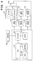
- Fig. 2 is a block diagram showing the arrangement of a control circuit of the ink-jet printer.
- reference numeral 1700 denotes an interface for inputting a printing signal from an external unit such as a host computer; 1701, an MPU; 1702, a ROM for storing a control program (including character fonts if necessary) executed by the MPU 1701; and 1703, a DRAM for storing various data (the printing signal, printing data supplied to the printhead, and the like).
- Reference numeral 1704 denotes a gate array for performing supply control of printing data to the printhead IJH. The gate array 1704 also performs data transfer control among the interface 1700, the MPU 1701, and the RAM 1703.
- Reference numeral 1710 denotes a carrier motor for conveying the ink cartridge IJC incorporating the printhead IJH with the carriage HC; and 1709, a shift motor for shifting a printing sheet.
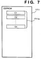
- Reference numeral 1705 denotes a head driver for driving the printhead IJH; 1706 and 1707, motor drivers for driving the transfer motor 1709 and the carrier motor 1710 respectively; and 1711, an EEPROM for maintaining information necessary for controlling suction operation even when the power of the printer is turned off.
- the printing signal is converted into printing data for a printing operation between the gate array 1704 and the MPU 1701.
- the motor drivers 1706 and 1707 are driven, and the printhead IJH is driven in accordance with the printing data supplied to the head driver 1705, thus performing the printing operation.
- controller also controls timing of recovery suction by the suction member 5015.
- the printhead IJH of the present embodiment has a plurality of ink-discharge nozzles arrayed in a recording-sheet shift direction. Each of ink droplets discharged from the nozzles is corresponding to one pixel (dot) on image formation.
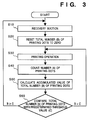
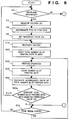
- step S10 the suction unit 5015 performs recovery suction.
- the suction unit 5015 first performs the above-described conventional suction operations (1) suction operation automatically performed upon installation of printhead to a printer; (2) automatic suction operation periodically performed during a long non-printing period, to avoid increase of ink viscosity and ink-stick to the orifices, suction is periodically made in accordance with the length of a non-printing period, as disclosed in Japanese Patent Application Laid-Open Nos. 60-2368 and 63-193846; and (3) manual suction operation in accordance with user's decision, in a case where excellent image quality cannot be obtained due to failure of ink-discharge.
- step S20 as the recovery suction has been made, the value of the total number B of printing dots is reset to "0".
- step S30 printing operation is performed.
- step S40 the number of ink droplets (number of printing dots: A) discharged from the printhead IJH in the printing operation in step S30 is counted.
- the MPU 1701 counts the number of dots which cause ink discharge, based on an input printing signal via the interface 1700.
- the counted number is regarded as the value of A.
- the value of the number A of printing dots corresponds to the total number of ink droplets (dots) discharged from the printhead IJH for delicate recovery.
- step S50 in which the number A of the printing dots counted in step S30 is added to the value of the total number B of printing dots stored in the EEPROM 1711, as a new value of the total number B. Then, this value is written into the EEPROM 1711, to update the previously stored value.
- step S60 the total number B of printing dots is compared with a predetermined threshold value C. If B ⁇ C holds, it is determined that it is not time where failure of ink-discharge due to air bubbles remained by successive printing operation may occur, and the process returns to step S30, to continue the printing operation. On the other hand, if B ⁇ C holds, it is determined that it is time where ink-discharge failure may occur due to air bubbles remained in successive printing operation, and the process returns to step S10, to perform the recovery suction. This operation prevents ink-discharge failure caused by air bubbles accumulated in a common liquid chamber in successive long printing operation.
- the number of ink droplets discharged from the printhead is counted, and the total number of ink droplets is accumulated by each printing operation, then when the accumulated value is equal to a predetermined threshold value or greater, recovery suction is performed. This enables execution of recovery suction at an appropriate point even in long printing operation, thus preventing ink-discharge failure, and maintaining excellent image printing.
- the number of ink droplets discharged from the printhead is counted by each printing operation.
- the discharge of ink droplets may occur when actual printing is not made. For example, immediately after the power of the printer is turned on, or if printing has not been performed more than a predetermined time, the printhead is moved to a home position to discharge ink, as preliminary discharge, so that printing operation can be stabilized.
- the number of ink droplets discharged in preliminary discharge is counted, then the counted value is added to a count value obtained from actual printing operation, and recovery suction is controlled based on the accumulated value.
- the MPU 1701 also counts the number of dots which cause preliminary discharge, based on dummy printing data generated in the MPU 1701.
- the printhead of this embodiment considering the fact that as temperature rises, the frequency of occurrence of air bubbles in the printhead becomes higher, the printhead of this embodiment has a thermosensor and performs recovery suction in accordance with measured temperature. Note that the printer of this embodiment has the same structure as described in the first embodiment, therefore the explanation of the structure of the printer will be omitted.
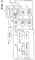
- Fig. 4 shows the construction of a controller according to this embodiment of the present invention.
- elements corresponding to those in Fig. 2 have the same reference numerals and the explanations of these elements will be omitted.
- the printhead has a thermosensor 1712, and measured results are transferred to the MPU 1701.
- step S40 After the processing in steps S10 to S30, the processing in step S40 is performed, and at the same time, in step S45, internal temperature of the printhead IJH is measured by the thermosensor 1712, as a measured value D.
- the relation between the temperature values D and weighting coefficients W are stored in the form of weighting table as shown below into the EEPROM 1711 or the ROM 1702: MEASURED TEMPERATURE (D) WEIGHTING COEFFICIENT (W) D1 W1 D2 W2 ... ... Dn Wn
- step S46 a weighting coefficient W most appropriate to the temperature value D is found in the weighting table.
- step S47 the number A of printing dots, counted in step S40, is multiplied by the obtained weighting coefficient W to obtain a number AE of effective printing dots.
- step S55 the number AE of the effective printing dots is added to the total number B of the printing dots, stored in the EEPROM 1711, as a new total number B. Then, this number B is written into the EEPROM 1711 to update the previously stored value.
- the actual temperature measurement by the thermosensor 1712 may be replaced with estimation of internal temperature of the printhead, by pre-storing a temperature estimation table, indicating the correlation between, e.g., the number of printing operations, the number A of printing dots or the total number B of printing dots, and internal temperature of the printhead, in the EEPROM 1711 or the ROM 1702, and referring to the table to estimate the internal temperature of the printhead.
- a temperature estimation table indicating the correlation between, e.g., the number of printing operations, the number A of printing dots or the total number B of printing dots, and internal temperature of the printhead, in the EEPROM 1711 or the ROM 1702, and referring to the table to estimate the internal temperature of the printhead.
- step S60 similar to the first embodiment, it is determined to continue the printing operation or to perform recovery suction.
- the values stored in the weighting table and the temperature estimation table reflect the fluctuation among apparatus depending upon quality of printers.
- the recovery suction is appropriately controlled in dependence upon internal temperature of the printhead, so that ink-discharge failure is prevented and excellent image printing can be maintained.
- the type of printhead e.g., color printhead, monochromatic printhead and so on
- control of recovery suction in accordance with the type of printhead will be described.
- the printer may comprise a sensor that discriminates the type of installed printhead or ink cartridge.
- the EEPROM or ROM may contain correction coefficients, correction term or threshold values according to the printheads or ink cartridges of various types, so as to control recovery suction in accordance with the type of printhead or ink cartridge.
- the total number of printing dots is compared with a predetermined threshold value corrected with the correction coefficient or correction term according to the type of installed printhead of ink cartridge, or with a threshold value according to the type of the printhead or ink cartridge.
- Fig. 6 shows the construction of the controller according to this embodiment.
- the printhead IJH has a resistor 1713, having a unique resistance value Ri according to the type of the printhead, for discrimination of the type of printhead.
- the MPU 1701 supplies low-voltage current to the resistor 1713, and based on the obtained voltage value (Vi) from the resistor 1713, discriminates the type of the printhead.
- the number of identifiable printhead types is n.
- the MPU 1701 selects one of the n threshold values 1711a stored in the EEPROM 1711 in accordance with the installed ink cartridge (printhead).
- step S2 whether the printhead has been exchanged or not is determined. If NO, the process proceeds to step S70, while if YES, proceeds to step S4, in which a voltage (Vi) based on a resistance value Ri of the resistor 1713 is read, and in step S6, the type of the printhead is discriminated based on the measured voltage value.
- step S8 a threshold value Ci is read out of the EEPROM 1171 in accordance with the discriminated type of printhead, and set as a threshold value to be used in the recovery-suction control processing. Thereafter, the process proceeds to step S10.
- a total number B of printing dots is compared with the selected threshold value Ci in step S60a. If B ⁇ Ci holds, it is determined that it is not time where air bubbles have accumulated to cause failure of ink discharge, then the process proceeds to step S70, to examine whether a print signal exists or not. If YES, the process returns to step S30, while if NO, returns to step S2.
- step S60a the process returns to step S10, similar to the first embodiment, to perform recovery suction.
- the combination of the second and third embodiments may attain recovery suction control depending upon the temperature and type of printhead.
- a printer which comprises means (e.g., an electrothermal transducer, laser beam generator, and the like) for generating heat energy as energy utilized upon execution of ink discharge, and causes a change in state of an ink by the heat energy, among the ink-jet printers.
- means e.g., an electrothermal transducer, laser beam generator, and the like
- heat energy as energy utilized upon execution of ink discharge
- the system is effective because, by applying at least one driving signal, which corresponds to printing information and gives a rapid temperature rise causing film boiling, to each of electrothermal transducers arranged in correspondence with a sheet or liquid channels holding a liquid (ink), heat energy is generated by the electrothermal transducer to effect film boiling on the heat acting surface of the printing head, and consequently, a bubble can be formed in the liquid (ink) in one-to-one correspondence with the driving signal.
- the driving signal is applied as a pulse signal, the growth and shrinkage of the bubble can be attained instantly and adequately to achieve discharge of the liquid (ink) with the particularly high response characteristics.
- signals disclosed in U.S. Patent Nos. 4,463,359 and 4,345,262 are suitable. Note that further excellent printing can be performed by using the conditions described in U.S. Patent No. 4,313,124 of the invention which relates to the temperature rise rate of the heat acting surface.
- the arrangement using U.S. Patent Nos. 4,558,333 and 4,459,600 which disclose the arrangement having a heat acting portion arranged in a flexed region is also included in the present invention.
- the present invention can be effectively applied to an arrangement based on Japanese Patent Laid-Open No. 59-123670 which discloses the arrangement using a slot common to a plurality of electrothermal transducers as a discharge portion of the electrothermal transducers, or Japanese Patent Laid-Open No. 59-138461 which discloses the arrangement having an opening for absorbing a pressure wave of heat energy in correspondence with a discharge portion.
- a full line type printing head having a length corresponding to the width of a maximum printing medium which can be printed by the printer, either the arrangement which satisfies the full-line length by combining a plurality of printing heads as disclosed in the above specification or the arrangement as a single printing head obtained by forming printing heads integrally can be used.
- an exchangeable chip type printing head which can be electrically connected to the apparatus main unit and can receive an ink from the apparatus main unit upon being mounted on the apparatus main unit
- a cartridge type printing head in which an ink tank is integrally arranged on the printing head itself can be applicable to the present invention.
- pressurization means and preliminary heating means using electrothermal transducers, another heating element, or a combination thereof for more stable printing.
- a printing mode of the printer not only a printing mode using only a primary color such as black or the like, but also at least one of a multi-color mode using a plurality of different colors or a full-color mode achieved by color mixing can be implemented in the printer either by using an integrated printing head or by combining a plurality of printing heads.
- the ink is a liquid.
- the present invention may employ an ink which is solid at room temperature or less and softens or liquefies at room temperature, or an ink which liquefies upon application of a use printing signal, since it is a general practice to perform temperature control of the ink itself within a range from 30°C to 70°C in the ink-jet system, so that the ink viscosity can fall within a stable discharge range.
- an ink which is solid in a non-use state and liquefies upon heating may be used.
- an ink which liquefies upon application of heat energy according to a printing signal and is discharged in a liquid state, an ink which begins to solidify when it reaches a printing medium, or the like, is applicable to the present invention.
- an ink may be situated opposite electrothermal transducers while being held in a liquid or solid state in recess portions of a porous sheet or through holes, as described in Japanese Patent Laid-Open No. 54-56847 or 60-71260.
- the above-mentioned film boiling system is most effective for the above-mentioned inks.
- the ink-jet printer of the present invention may be used in the form of a copying machine combined with a reader, and the like, or a facsimile apparatus having a transmission/reception function in addition to an image output terminal of an information processing equipment such as a computer.
- the present invention can be applied to a system constituted by a plurality of devices, or to an apparatus comprising a single device. Furthermore, the invention is applicable also to a case where the object of the invention is attained by supplying a program to a system or apparatus.
- a storage medium, storing a program according to the invention constitutes the invention.
- the system or apparatus installed with the program read from the medium realizes the functions according to the invention.
Landscapes
- Ink Jet (AREA)
Applications Claiming Priority (3)
| Application Number | Priority Date | Filing Date | Title |
|---|---|---|---|
| JP179217/94 | 1994-07-29 | ||
| JP17921794 | 1994-07-29 | ||
| JP17921794 | 1994-07-29 |
Publications (3)
| Publication Number | Publication Date |
|---|---|
| EP0694403A2 EP0694403A2 (en) | 1996-01-31 |
| EP0694403A3 EP0694403A3 (en) | 1996-09-11 |
| EP0694403B1 true EP0694403B1 (en) | 1999-11-03 |
Family
ID=16061990
Family Applications (1)
| Application Number | Title | Priority Date | Filing Date |
|---|---|---|---|
| EP95305179A Expired - Lifetime EP0694403B1 (en) | 1994-07-29 | 1995-07-25 | Recovery method for ink jet printer |
Country Status (5)
| Country | Link |
|---|---|
| US (1) | US6382764B1 (es) |
| EP (1) | EP0694403B1 (es) |
| DE (1) | DE69513099T2 (es) |
| ES (1) | ES2139150T3 (es) |
| SG (1) | SG52160A1 (es) |
Families Citing this family (19)
| Publication number | Priority date | Publication date | Assignee | Title |
|---|---|---|---|---|
| DE69828859T2 (de) * | 1997-11-14 | 2006-03-16 | Canon K.K. | Tintenstrahdrucker |
| JPH11348319A (ja) * | 1998-06-03 | 1999-12-21 | Canon Inc | インクジェット記録装置および該装置の制御方法 |
| JP3667117B2 (ja) * | 1998-10-27 | 2005-07-06 | キヤノン株式会社 | インクジェット記録装置および該装置における吐出回復方法 |
| JP3258633B2 (ja) * | 1998-11-26 | 2002-02-18 | キヤノン株式会社 | インクジェット記録装置及び方法並びに印刷システムとその制御方法 |
| JP3884878B2 (ja) * | 1999-02-24 | 2007-02-21 | キヤノン株式会社 | 記録装置及び吸引回復制御方法 |
| JP3994636B2 (ja) | 2000-06-09 | 2007-10-24 | セイコーエプソン株式会社 | インクジェット式記録装置 |
| JP4646419B2 (ja) * | 2001-02-23 | 2011-03-09 | キヤノン株式会社 | インクジェット記録装置及びインクジェット記録装置の制御方法 |
| JP2004025851A (ja) | 2002-05-02 | 2004-01-29 | Canon Inc | インクジェット記録装置及び記録方法 |
| JP2003326744A (ja) * | 2002-05-14 | 2003-11-19 | Canon Inc | インクジェット記録装置 |
| JP2004114650A (ja) * | 2002-09-30 | 2004-04-15 | Canon Finetech Inc | 記録装置 |
| JP4464150B2 (ja) * | 2003-02-26 | 2010-05-19 | キヤノン株式会社 | インクジェット記録装置及びそのクリーニング制御方法 |
| TW200508044A (en) | 2003-08-26 | 2005-03-01 | Ind Tech Res Inst | Compound inkjet print head printer |
| US7111932B2 (en) * | 2003-09-18 | 2006-09-26 | Hewlett-Packard Development Company | Managing contaminants in a fluid-delivery device |
| US7093930B2 (en) * | 2003-09-18 | 2006-08-22 | Hewlett-Packard Development Company, L.P. | Managing bubbles in a fluid-delivery device |
| US7252359B2 (en) * | 2004-09-22 | 2007-08-07 | Canon Finetech Inc. | Inkjet recording device and recovery processing method |
| US7261480B2 (en) * | 2004-11-23 | 2007-08-28 | Pitney Bowes Inc. | Print shaft contamination detector |
| US8272704B2 (en) * | 2008-05-22 | 2012-09-25 | Zipher Limited | Ink containment system and ink level sensing system for an inkjet cartridge |
| US8091993B2 (en) * | 2008-05-22 | 2012-01-10 | Videojet Technologies Inc. | Ink containment system and ink level sensing system for an inkjet cartridge |
| CN106696464B (zh) * | 2015-07-29 | 2018-09-11 | 三纬国际立体列印科技股份有限公司 | 调整三维打印机喷头使用量的方法及控制装置 |
Family Cites Families (37)
| Publication number | Priority date | Publication date | Assignee | Title |
|---|---|---|---|---|
| CA1127227A (en) | 1977-10-03 | 1982-07-06 | Ichiro Endo | Liquid jet recording process and apparatus therefor |
| JPS5936879B2 (ja) | 1977-10-14 | 1984-09-06 | キヤノン株式会社 | 熱転写記録用媒体 |
| US4330787A (en) | 1978-10-31 | 1982-05-18 | Canon Kabushiki Kaisha | Liquid jet recording device |
| US4345262A (en) | 1979-02-19 | 1982-08-17 | Canon Kabushiki Kaisha | Ink jet recording method |
| US4463359A (en) | 1979-04-02 | 1984-07-31 | Canon Kabushiki Kaisha | Droplet generating method and apparatus thereof |
| US4313124A (en) | 1979-05-18 | 1982-01-26 | Canon Kabushiki Kaisha | Liquid jet recording process and liquid jet recording head |
| US4558333A (en) | 1981-07-09 | 1985-12-10 | Canon Kabushiki Kaisha | Liquid jet recording head |
| JPS59123670A (ja) | 1982-12-28 | 1984-07-17 | Canon Inc | インクジエツトヘツド |
| JPS59138461A (ja) | 1983-01-28 | 1984-08-08 | Canon Inc | 液体噴射記録装置 |
| JPS602368A (ja) | 1983-06-21 | 1985-01-08 | Canon Inc | インクジエツトプリンタ |
| JPS6071260A (ja) | 1983-09-28 | 1985-04-23 | Erumu:Kk | 記録装置 |
| US4926196A (en) * | 1986-12-25 | 1990-05-15 | Canon Kabushiki Kaisha | Ink jet printer |
| JPS63193845A (ja) | 1987-02-05 | 1988-08-11 | Nec Corp | インクジエツトヘツド保護機構 |
| JPS63193846A (ja) | 1987-02-06 | 1988-08-11 | Canon Inc | インクジエツト記録装置 |
| JP2789339B2 (ja) | 1988-11-24 | 1998-08-20 | キヤノン株式会社 | インクジェット記録装置 |
| US5068806A (en) * | 1988-12-02 | 1991-11-26 | Spectra-Physics, Inc. | Method of determining useful life of cartridge for an ink jet printer |
| DK0997296T3 (da) * | 1989-08-05 | 2006-04-03 | Canon Kk | Blækstråleskriveapparat og blækpatron til apparatet |
| JP2774638B2 (ja) * | 1990-02-13 | 1998-07-09 | キヤノン株式会社 | インクジェット記録装置の回復制御方法 |
| EP0442438B1 (en) | 1990-02-13 | 1994-05-25 | Canon Kabushiki Kaisha | Ink jet recording apparatus |
| US5166699A (en) * | 1990-04-11 | 1992-11-24 | Canon Kabushiki Kaisha | Recording apparatus |
| JP2804613B2 (ja) | 1990-07-24 | 1998-09-30 | キヤノン株式会社 | インクジェット記録方法およびその装置 |
| JPH0493260A (ja) | 1990-08-08 | 1992-03-26 | Fuji Electric Co Ltd | インクジェット・プリンタ |
| JPH04141442A (ja) | 1990-10-02 | 1992-05-14 | Nec Corp | インクジェットプリンタ |
| JP2974487B2 (ja) | 1991-03-20 | 1999-11-10 | キヤノン株式会社 | 記録装置 |
| JP2885959B2 (ja) | 1991-05-22 | 1999-04-26 | キヤノン株式会社 | インクジェット記録装置 |
| JP2955396B2 (ja) | 1991-06-06 | 1999-10-04 | キヤノン株式会社 | インクジェット記録装置 |
| CA2074906C (en) * | 1991-08-01 | 2000-09-12 | Hiromitsu Hirabayashi | Ink jet recording apparatus having temperature control function |
| JPH0592579A (ja) | 1991-10-03 | 1993-04-16 | Canon Inc | インクジエツト記録装置 |
| JPH07186430A (ja) * | 1991-11-04 | 1995-07-25 | Eastman Kodak Co | 感熱プリンタ |
| US5363134A (en) * | 1992-05-20 | 1994-11-08 | Hewlett-Packard Corporation | Integrated circuit printhead for an ink jet printer including an integrated identification circuit |
| JPH0671875A (ja) * | 1992-06-30 | 1994-03-15 | Fuji Xerox Co Ltd | インクジェット記録装置 |
| DE69315159T2 (de) * | 1992-09-25 | 1998-03-12 | Hewlett Packard Co | Verfahren und Vorrichtung zur Steuerung eines Farbstrahldruckers mittels Tropfenzählung |
| JPH06122206A (ja) | 1992-10-13 | 1994-05-06 | Canon Inc | インクジェット記録ヘッドの回復制御方法 |
| US5617122A (en) * | 1992-12-10 | 1997-04-01 | Canon Kabushiki Kaisha | Recording apparatus and method for controlling recording head driving timing |
| JPH06238914A (ja) * | 1993-02-12 | 1994-08-30 | Canon Inc | インクジェット記録装置の吸引動作制御方法およびインクジェット記録装置 |
| JP3397371B2 (ja) * | 1993-05-27 | 2003-04-14 | キヤノン株式会社 | 記録装置および記録方法 |
| US5646655A (en) * | 1993-08-31 | 1997-07-08 | Canon Kabushiki Kaisha | Recording apparatus and temperature detecting method therefor |
-
1995
- 1995-07-24 US US08/506,025 patent/US6382764B1/en not_active Expired - Lifetime
- 1995-07-25 DE DE69513099T patent/DE69513099T2/de not_active Expired - Lifetime
- 1995-07-25 EP EP95305179A patent/EP0694403B1/en not_active Expired - Lifetime
- 1995-07-25 ES ES95305179T patent/ES2139150T3/es not_active Expired - Lifetime
- 1995-07-28 SG SG1995000975A patent/SG52160A1/en unknown
Also Published As
| Publication number | Publication date |
|---|---|
| ES2139150T3 (es) | 2000-02-01 |
| SG52160A1 (en) | 1998-09-28 |
| US6382764B1 (en) | 2002-05-07 |
| DE69513099T2 (de) | 2000-04-27 |
| EP0694403A2 (en) | 1996-01-31 |
| DE69513099D1 (de) | 1999-12-09 |
| EP0694403A3 (en) | 1996-09-11 |
Similar Documents
| Publication | Publication Date | Title |
|---|---|---|
| EP0694403B1 (en) | Recovery method for ink jet printer | |
| US5946007A (en) | Temperature control of ink-jet recording head using heat energy | |
| JP3117849B2 (ja) | 記録濃度むら補正機能を有する記録装置および記録濃度むら補正方法 | |
| EP0670219B1 (en) | A printhead for a printing apparatus | |
| US6193344B1 (en) | Ink jet recording apparatus having temperature control function | |
| EP0709192B1 (en) | Method and apparatus for correcting printhead, printhead corrected by this apparatus, and printing apparatus using this printhead | |
| US7438374B2 (en) | Inkjet printing apparatus, printing control method for inkjet printing apparatus, program, and storage medium | |
| JP3376112B2 (ja) | インクジェット装置およびその回復制御方法 | |
| US6752485B2 (en) | Printing apparatus and suction recovery control method | |
| US6629789B2 (en) | Printing apparatus, driving condition setting method for printhead, and storage medium | |
| EP0710562B1 (en) | Printer | |
| US6382765B1 (en) | Ink-jet printing apparatus and discharge recovery method therefor | |
| EP0505154A2 (en) | Thermal ink jet recording head temperature control | |
| JP4579557B2 (ja) | 記録装置及びその制御方法、プログラム | |
| US6655772B2 (en) | Printing apparatus and printhead temperature management method | |
| EP0732217B1 (en) | Recording head and apparatus for detecting contact condition | |
| JPH11157058A (ja) | プリンタドライバ、画像形成装置及びその制御方法 | |
| US6824236B2 (en) | Printing apparatus and ink-consumption amount management method | |
| US6979068B2 (en) | Printing apparatus and control method thereof | |
| EP0576285A2 (en) | Ink jet recording method and apparatuses | |
| JPH1120148A (ja) | インクジェット記録装置の制御方法およびインクジェット記録装置 | |
| US6076916A (en) | Printing apparatus and driving method therefor | |
| US6406112B1 (en) | Ink jet recording apparatus, recording control method, and storage medium with recording control program stored therein | |
| JP3530635B2 (ja) | 記録方法及びその記録装置 | |
| JPH04133747A (ja) | 画像形成装置 |
Legal Events
| Date | Code | Title | Description |
|---|---|---|---|
| PUAI | Public reference made under article 153(3) epc to a published international application that has entered the european phase |
Free format text: ORIGINAL CODE: 0009012 |
|
| AK | Designated contracting states |
Kind code of ref document: A2 Designated state(s): CH DE ES FR GB IT LI NL |
|
| PUAL | Search report despatched |
Free format text: ORIGINAL CODE: 0009013 |
|
| AK | Designated contracting states |
Kind code of ref document: A3 Designated state(s): CH DE ES FR GB IT LI NL |
|
| 17P | Request for examination filed |
Effective date: 19970122 |
|
| 17Q | First examination report despatched |
Effective date: 19971205 |
|
| GRAG | Despatch of communication of intention to grant |
Free format text: ORIGINAL CODE: EPIDOS AGRA |
|
| GRAG | Despatch of communication of intention to grant |
Free format text: ORIGINAL CODE: EPIDOS AGRA |
|
| GRAG | Despatch of communication of intention to grant |
Free format text: ORIGINAL CODE: EPIDOS AGRA |
|
| GRAH | Despatch of communication of intention to grant a patent |
Free format text: ORIGINAL CODE: EPIDOS IGRA |
|
| GRAH | Despatch of communication of intention to grant a patent |
Free format text: ORIGINAL CODE: EPIDOS IGRA |
|
| GRAA | (expected) grant |
Free format text: ORIGINAL CODE: 0009210 |
|
| AK | Designated contracting states |
Kind code of ref document: B1 Designated state(s): CH DE ES FR GB IT LI NL |
|
| REG | Reference to a national code |
Ref country code: CH Ref legal event code: EP |
|
| REF | Corresponds to: |
Ref document number: 69513099 Country of ref document: DE Date of ref document: 19991209 |
|
| ET | Fr: translation filed | ||
| REG | Reference to a national code |
Ref country code: CH Ref legal event code: NV Representative=s name: BOVARD AG PATENTANWAELTE |
|
| ITF | It: translation for a ep patent filed |
Owner name: SOCIETA' ITALIANA BREVETTI S.P.A. |
|
| REG | Reference to a national code |
Ref country code: ES Ref legal event code: FG2A Ref document number: 2139150 Country of ref document: ES Kind code of ref document: T3 |
|
| PLBE | No opposition filed within time limit |
Free format text: ORIGINAL CODE: 0009261 |
|
| STAA | Information on the status of an ep patent application or granted ep patent |
Free format text: STATUS: NO OPPOSITION FILED WITHIN TIME LIMIT |
|
| 26N | No opposition filed | ||
| REG | Reference to a national code |
Ref country code: GB Ref legal event code: IF02 |
|
| PGFP | Annual fee paid to national office [announced via postgrant information from national office to epo] |
Ref country code: ES Payment date: 20100615 Year of fee payment: 16 |
|
| PGFP | Annual fee paid to national office [announced via postgrant information from national office to epo] |
Ref country code: NL Payment date: 20100715 Year of fee payment: 16 Ref country code: CH Payment date: 20100715 Year of fee payment: 16 |
|
| REG | Reference to a national code |
Ref country code: CH Ref legal event code: PFA Owner name: CANON KABUSHIKI KAISHA Free format text: CANON KABUSHIKI KAISHA#30-2, 3-CHOME, SHIMOMARUKO, OHTA-KU#TOKYO (JP) -TRANSFER TO- CANON KABUSHIKI KAISHA#30-2, 3-CHOME, SHIMOMARUKO, OHTA-KU#TOKYO (JP) |
|
| REG | Reference to a national code |
Ref country code: NL Ref legal event code: V1 Effective date: 20120201 |
|
| REG | Reference to a national code |
Ref country code: CH Ref legal event code: PL |
|
| PG25 | Lapsed in a contracting state [announced via postgrant information from national office to epo] |
Ref country code: CH Free format text: LAPSE BECAUSE OF NON-PAYMENT OF DUE FEES Effective date: 20110731 Ref country code: LI Free format text: LAPSE BECAUSE OF NON-PAYMENT OF DUE FEES Effective date: 20110731 |
|
| PG25 | Lapsed in a contracting state [announced via postgrant information from national office to epo] |
Ref country code: NL Free format text: LAPSE BECAUSE OF NON-PAYMENT OF DUE FEES Effective date: 20120201 |
|
| REG | Reference to a national code |
Ref country code: ES Ref legal event code: FD2A Effective date: 20121122 |
|
| PG25 | Lapsed in a contracting state [announced via postgrant information from national office to epo] |
Ref country code: ES Free format text: LAPSE BECAUSE OF NON-PAYMENT OF DUE FEES Effective date: 20110726 |
|
| PGFP | Annual fee paid to national office [announced via postgrant information from national office to epo] |
Ref country code: DE Payment date: 20140731 Year of fee payment: 20 |
|
| PGFP | Annual fee paid to national office [announced via postgrant information from national office to epo] |
Ref country code: FR Payment date: 20140728 Year of fee payment: 20 Ref country code: GB Payment date: 20140724 Year of fee payment: 20 |
|
| PGFP | Annual fee paid to national office [announced via postgrant information from national office to epo] |
Ref country code: IT Payment date: 20140702 Year of fee payment: 20 |
|
| REG | Reference to a national code |
Ref country code: DE Ref legal event code: R071 Ref document number: 69513099 Country of ref document: DE |
|
| REG | Reference to a national code |
Ref country code: GB Ref legal event code: PE20 Expiry date: 20150724 |
|
| PG25 | Lapsed in a contracting state [announced via postgrant information from national office to epo] |
Ref country code: GB Free format text: LAPSE BECAUSE OF EXPIRATION OF PROTECTION Effective date: 20150724 |