EP0690192B1 - Tür oder fenster mit einem wendeflügellager - Google Patents
Tür oder fenster mit einem wendeflügellager Download PDFInfo
- Publication number
- EP0690192B1 EP0690192B1 EP95104106A EP95104106A EP0690192B1 EP 0690192 B1 EP0690192 B1 EP 0690192B1 EP 95104106 A EP95104106 A EP 95104106A EP 95104106 A EP95104106 A EP 95104106A EP 0690192 B1 EP0690192 B1 EP 0690192B1
- Authority
- EP
- European Patent Office
- Prior art keywords
- bearing
- window
- door
- accordance
- journal
- Prior art date
- Legal status (The legal status is an assumption and is not a legal conclusion. Google has not performed a legal analysis and makes no representation as to the accuracy of the status listed.)
- Expired - Lifetime
Links
- 230000037431 insertion Effects 0.000 claims abstract 2
- 238000003780 insertion Methods 0.000 claims abstract 2
- 230000008878 coupling Effects 0.000 claims description 8
- 238000010168 coupling process Methods 0.000 claims description 8
- 238000005859 coupling reaction Methods 0.000 claims description 8
- 238000006073 displacement reaction Methods 0.000 claims description 2
- 238000010008 shearing Methods 0.000 claims 1
- 230000002441 reversible effect Effects 0.000 description 19
- 238000009434 installation Methods 0.000 description 2
- 238000000034 method Methods 0.000 description 1
Images

Classifications
-
- E—FIXED CONSTRUCTIONS
- E05—LOCKS; KEYS; WINDOW OR DOOR FITTINGS; SAFES
- E05D—HINGES OR SUSPENSION DEVICES FOR DOORS, WINDOWS OR WINGS
- E05D7/00—Hinges or pivots of special construction
- E05D7/08—Hinges or pivots of special construction for use in suspensions comprising two spigots placed at opposite edges of the wing, especially at the top and the bottom, e.g. trunnions
- E05D7/082—Hinges or pivots of special construction for use in suspensions comprising two spigots placed at opposite edges of the wing, especially at the top and the bottom, e.g. trunnions the pivot axis of the wing being situated at a considerable distance from the edges of the wing, e.g. for balanced wings
- E05D7/083—Hinges or pivots of special construction for use in suspensions comprising two spigots placed at opposite edges of the wing, especially at the top and the bottom, e.g. trunnions the pivot axis of the wing being situated at a considerable distance from the edges of the wing, e.g. for balanced wings with a fixed pivot axis
-
- E—FIXED CONSTRUCTIONS
- E05—LOCKS; KEYS; WINDOW OR DOOR FITTINGS; SAFES
- E05Y—INDEXING SCHEME ASSOCIATED WITH SUBCLASSES E05D AND E05F, RELATING TO CONSTRUCTION ELEMENTS, ELECTRIC CONTROL, POWER SUPPLY, POWER SIGNAL OR TRANSMISSION, USER INTERFACES, MOUNTING OR COUPLING, DETAILS, ACCESSORIES, AUXILIARY OPERATIONS NOT OTHERWISE PROVIDED FOR, APPLICATION THEREOF
- E05Y2900/00—Application of doors, windows, wings or fittings thereof
- E05Y2900/10—Application of doors, windows, wings or fittings thereof for buildings or parts thereof
- E05Y2900/13—Type of wing
- E05Y2900/148—Windows
Definitions
- the invention relates to a door or a window with a Reversible wing bearing for a rotatable around a vertical axis Wing of a window or door, the wing by means of an upper and lower bearing on one fixed frame is stored and each bearing from one Wing bearing part and a frame bearing part consists of one bearing journal and the other one this has receiving bearing shell which is divisible in such a way that the trunnion radially into a fixed bearing shell part usable and with the other bearing shell part after Insert in the bearing shell can be fixed, the The bearing journal protrudes from a body held in the bearing.
- a door is known from DE 19 53 735 A.
- the DE-AS 10 61 228 discloses e.g. one consisting of two parts Reversible wing bearing, in which the parts have a Hinge bolts are connected to each other.
- the window sash must first on the frame bearing part fixed window frame and the hinge pin Wing bearing part are attached to the frame bearing part. Then a retaining bolt of the window sash can be inserted into the Wing bearing part inserted and there over a Holding screw can be fixed.
- EP 558 968 A1 is a rotary bearing for one Swinging wing of a window became known, too from a frame bearing part and a wing bearing part consists.
- the wing bearing part in which the axis of rotation lies horizontally, the wing bearing part has an in Direction on the frame bearing part protruding journal on, which serves as a pivot bearing and in a bearing shell of the Frame bearing part comes to rest. Easy to hang up is guaranteed with this swivel wing bearing that the bearing shell of the frame bearing part with a radial Recess is provided, through which the journal of the Wing bearing part is insertable into the bearing shell. Located If the bearing journal is in the bearing shell, this closed an appropriately trained element.
- the pivot axis of the reversible wing bearing extends Window sash in the vertical direction and that of the warehouse forces to be absorbed act in the direction of the bearing axis, so that the reversible wing bearing can be specially designed for this got to.
- the invention is therefore based on the object To design reversible wing bearings of the type mentioned at the outset, that easy assembly and adjustment of the window sash possibly even by a single person. Here but should the forces occurring in the vertical direction still be supported safely.
- the Bearing journal carries a thrust bearing, which is on the one hand an axial face of the body and on the other an axial bearing surface of the receiving the journal Bearing shell supports, the axial bearing in the bearing part and / or the support point on the other bearing part in the axial Direction are adjustable, with the thrust bearing on an insert is attached that in one of the bearing parts in axially displaceable with respect to this bearing part, but is non-rotatably mounted.
- the use of a height adjustment device is in the bearing part slidably mounted. About the Height adjustment device can now use and over this the thrust bearing can be adjusted in height, focusing on the thrust bearing supports the other bearing part and thus the axial relative position of the two bearing parts to each other is adjustable.
- the thrust bearing or insert can be used e.g. be provided in the wing bearing part, so that the entire wing with the thrust bearing on the one below Support frame part. Movable storage of the Use compared to a direct movable storage the thrust bearing has the advantage that the use with Provide contact surfaces for the height adjustment device can be used as a thrust bearing and a series part which is e.g. is put on the insert.
- the height adjustment device of an axial screw is screwed in or out.
- Rotation of this screw can shift the insert axially be, whereby the thrust bearing, which the bearing surface forms for the other bearing part, also axially shifted becomes.
- the height adjustment screw is e.g. about a suitable tool, e.g. an Allen key twisted, this tool from the outside via a Height adjustment screw opening on the height adjustment screw can be introduced.
- bearing journal is intended for use.
- the bearing pin engages the thrust bearing and thus also has one Holding function and centering-alignment function for the bearing. After inserting the window sash where the Bearing journal in the bearing shell provided is inserted, the support is inevitably correct on the thrust bearing, so that not particularly must be respected.
- the insert preferably has a polygonal, in particular hexagonal body, which in a corresponding recess can be inserted into the bearing part.
- the hexagon shape ensures a torsion-proof storage of use in the corresponding bearing part, so that the Defined rotary movements initiated in the thrust bearing become. This can also be used to prevent rotation be attached.
- a locking pin Via a locking pin, e.g. via one in the storage part fixed shear pin, the use is captive held.
- the window sash When replacing the window sash is on this way ensures that when the Reversible leaf bearings use with thrust bearings safely in the corresponding reversible wing bearing part is held so that when the insert is intended in the wing bearing part, this protrudes down.
- An optimal seal between the outside of the bearing and the frame or window sash is achieved in that the two bearing parts on their the journal or the Bearing shell facing away from the outside each a receptacle for have a seal.
- the recordings are aligned assembled and closed reversible wing bearing.
- these receptacles can be used a seal or these recordings are designed so that a seal is pushed over or clipped on, in which case the Shots are designed as a T-shaped web and the T-beam extends parallel to the outer surface of the bearing.
- Wing bearing part with a sliding coupling for transferring closing movements from Central locking rods is provided.
- Optimal guidance of the coupling in the wing bearing part is achieved by using one or more, in Ridges extending in the longitudinal direction of the bearing part Wing bearing part is slidably mounted. These bridges ensure a jam-free displacement of the clutch as well their essentially play-free storage.
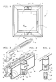
- FIG. 1 shows a window labeled 1 overall, in which about a vertical axis 2 a wing 3 in one Frame 4 is rotatable. A locking of the wing 3 at closed window 1 takes place via a handle 5.
- the Wing 3 is over an upper and a lower one Reversible wing bearing 6 rotatably attached to the frame 4.
- the Reversible wing bearing 6 consists of a wing bearing part 7, which is attached to the wing 3, and a frame bearing part 8, which is attached to the frame 4.
- the wing bearing part 7 rotates with the wing 3 about the vertical axis 2, whereas the frame bearing part 8 is fixed.
- the reversible wing bearing 6 in shown perspective view, clearly the housing-like structure of the wing bearing part 7 can be seen, in which a clutch 9, which is shown in a separate representation in Figure 3 is shown, in the longitudinal direction of the reversible wing bearing 6 is slidably mounted.
- a clutch 9 which is shown in a separate representation in Figure 3 is shown, in the longitudinal direction of the reversible wing bearing 6 is slidably mounted.
- guide webs 10 serve guide webs 10, which in a housing opening 11 receiving the clutch 9 protrude and into a middle part 12 of the coupling 9 engage provided guide grooves 13.
- the clutch 9 is essentially L-shaped, which is clear from the figure 3 is recognizable. It consists of an L-shaped Coupling rail 14, being at the free end of the short L-leg a coupling member 15 is provided.
- To the free ends of the coupling 9 are coupling pins 16, on the central locking rods, not shown can be coupled.
- FIG. 2 two support pins 17 can be seen, the Attack sash 3 of window 1 and wear it.
- a T-shaped profile web 18 can be seen, the themselves over the length of the reversible wing bearing 6 Back stretches.
- This profile web 18 that clearly Figure 5 can be seen consists of two sections 19 and 20, which are aligned with the reversible wing bearing 6 closed and assigned to the wing bearing part 7 or the frame bearing part 8 are.
- This profile web 18 or sections 19 and 20 are provided for receiving a seal 21 (FIG. 6), which can be pushed or clipped on via the T-bar. over this seal 21 becomes the wing 3 or the frame 4th sealed against the reversible wing bearing 6 to the outside and the joint 46 between the frame and casement locked.
- FIG. 4 is a perspective view of the Bearing head 23 in the direction of arrow IV according to FIG. 2 shown, it being clearly recognizable that the bearing head 23 has a window 24 through which an acceptable Bearing shell part 25 is closable. It is also through the window 24 shows a bearing pin 26.
- Allen screw 27 which is in a corresponding Threaded bore 28 ( Figure 7) engages in the bearing head 23.
- the trunnion 26 engages in the bearing head 23.
- the trunnion 26 engages in the bearing head 23.
- the trunnion 26 engages in the bearing head 23.
- the trunnion 26 engages in the bearing head 23.
- the trunnion 26 engages in the bearing head 23.
- the trunnion 26 engages in the bearing head 23.
- the trunnion 26 engages in the bearing head 23.
- the trunnion 26 engages in the bearing head 23.
- the trunnion 26 engage
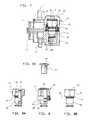
- FIG. 7 which shows a section VII-VII according to FIG. 2, it can be clearly seen that the journal 26 on one a total of 32 designated use is provided.
- This Insert 32 is shown enlarged in FIG has a hexagonal body 33, which in a corresponding, i.e. hexagonal recess 34 in Bearing head 22 is mounted against rotation. After this The body 33 is inserted into the recess 34 Shear pin 35, the axis of which is transverse to the axis 2 of the Insert 23 is located in a recess 36 of the body 33 intervenes, kept captive. Following the Body 33 follows the journal 26, which is in the immediate vicinity Neighboring the body 33 a knurled collar 37 having.
- This collar 37 tapers in the direction of Bearing pin 26 slightly (see Figure 8b), so that a thrust bearing 38, e.g. an axial deep groove ball bearing can be pushed on and anchored.
- This Axial bearing 38 is in turn axially supported on the Face 39 of the body 33.
- the thrust bearing 38 has a support surface 40, which acts in the axial direction Can absorb pressure forces.
- This bearing surface 40 supports itself on the end face 41 ( Figures 6 and 7) of the bearing head 23 from.
- the insert 32 in particular the body 33 with a threaded blind hole 42 is provided, in which a height adjustment screw 43 can be screwed in.
- This height adjustment screw 43 has an internal hexagon 44 through a Height adjustment screw opening 45 is accessible.
- a suitable tool Height adjustment screw 43 rotated and in the insert 32 screwed or unscrewed.
- the body 33 in Figure 7 down the wing bearing part 7 is moved or moved by the frame bearing part 8 lifted because the body 33 on the thrust bearing 38 the end face 41 of the bearing head 23 and thus on Frame bearing part 8 supports.
- unscrewing the Height adjustment screw 43 can therefore be the height of the Wing bearing part 7 with respect to the frame bearing part 8 be adjusted.
Landscapes
- Engineering & Computer Science (AREA)
- Mechanical Engineering (AREA)
- Hinges (AREA)
- Wing Frames And Configurations (AREA)
- Seal Device For Vehicle (AREA)
- Escalators And Moving Walkways (AREA)
- Forging (AREA)
- Materials For Medical Uses (AREA)
- Sliding-Contact Bearings (AREA)
Description
- Figur 1
- eine Gesamtansicht eines geschlossenen Wendeflügelfensters;
- Figur 2
- eine perspektivische Ansicht eines geschlossenen Wendeflügellagers;
- Figur 3
- eine perspektivische Ansicht einer Kupplung;
- Figur 4
- eine perspektivische Ansicht in Richtung des Pfeils IV gemäß Figur 2 auf einen Abschnitt des Flügellagerteils;
- Figur 5
- eine perspektivische Ansicht auf die Rückseite des geschlossenen Wendeflügellagers;
- Figur 6
- einen Schnitt VI-VI gemäß Figur 1;
- Figur 7
- einen Schnitt VII-VII gemäß Figur 2; und
- Figur 8
- einen Einsatz teilweise geschnitten und in verschiedenen Ansichten.
Claims (11)
- Tür oder Fenster mit einem Wendeflügellager mit einem um eine vertikale Achse (2) drehbaren Flügel (3) des Fensters oder der Tür, wobei der Flügel (3) mittels eines oberen und unteren Lagers (6) an einem feststehenden Rahmen (4) gelagert ist und jedes Lager (6) aus einem Flügellagerteil (7) sowie aus einem Rahmenlagerteil (8) besteht, von denen eines einen Lagerzapfen (26) und das andere eine diesen aufnehmende Lagerschale aufweist, die derart teilbar ist, dass der Lagerzapfen (26) radial in einen festen Lagerschalenteil einsetzbar und mit dem anderen Lagerschalenteil (25) nach dem Einsetzen in der Lagerschale festlegbar ist, wobei der Lagerzapfen (26) von einem im Lager gehaltenen Körper (33) abragt, dadurch gekennzeichnet, dass der Lagerzapfen (26) ein Axiallager (38) trägt, welches sich einerseits an einer axialen Stirnfläche (39) des Körpers (33) und andererseits an einer axialen Auflagefläche der den Lagerzapfen (26) aufnehmenden Lagerschale abstützt, wobei das Axiallager (38) in dessen Lagerteil und/oder die Abstützstelle am anderen Lagerteil in axialer Richtung verstellbar sind bzw. ist, wobei das Axiallager (38) an einem Einsatz (32) angebracht ist, der in einem der Lagerteile (7 oder 8) in axialer Richtung bezüglich dieses Lagerteils (7 oder 8) verschieblich, jedoch drehfest gelagert ist.
- Tür oder Fenster nach Anspruch 1, dadurch gekennzeichnet, daß der Einsatz (32) über eine Höheneinstellvorrichtung in dessen Lagerteil (7 oder 8) verschiebbar ist.
- Tür oder Fenster nach Anspruch 2, dadurch gekennzeichnet, daß die Höheneinstellvorrichtung von einer axial ein-bzw. ausdrehbaren Schraube (43) gebildet wird.
- Tür oder Fenster nach Anspruch 3, dadurch gekennzeichnet, daß die Höheneinstellschraube (43) z.B. über eine Höheneinstellschraubenöffnung (45) von außen zum Zwecke der Verdrehung zugänglich ist.
- Tür oder Fenster nach einem der vorhergehenden Ansprüche, dadurch gekennzeichnet, daß der Lagerzapfen (26) am Einsatz (32) angeformt ist.
- Tür oder Fenster nach einem der vorhergehenden Ansprüche, dadurch gekennzeichnet, daß der Lagerzapfen (26) das Axiallager (38) durchgreift.
- Tür oder Fenster nach einem der vorhergehenden Ansprüche, dadurch gekennzeichnet, daß das Axiallager (38) bzw. der Einsatz (32) verdrehsicher und/oder verliersicher in dessen Lagerteil (7 oder 8) aufgenommen ist.
- Tür oder Fenster nach einem der vorhergehenden Ansprüche, dadurch gekennzeichnet, daß der Einsatz (32) einen polygonförmigen, insbesondere sechskant-förmigen Körper (33) aufweist, der in eine entsprechende Ausnehmung (34) in das Lagerteil (7 oder 8) einsetzbar ist.
- Tür oder Fenster nach einem der vorhergehenden Ansprüche, dadurch gekennzeichnet, daß der Einsatz (32) über einen Sicherungsstift, z.B. über einen im Lagerteil festgelegten Scherspannstift (35) verliersicher gehalten ist.
- Tür oder Fenster nach einem der vorhergehenden Ansprüche, dadurch gekennzeichnet, daß die beiden Lagerteile (7 und 8) an ihrer dem Lagerzapfen (26) bzw. der Lagerschale abgewandten Außenseite jeweils eine Aufnahme, z.B. einen Profilsteg (18), für eine Dichtung aufweisen.
- Tür oder Fenster nach einem der vorhergehenden Ansprüche, dadurch gekennzeichnet, daß das Flügellagerteil (7) mit einer insbesondere in einem oder mehreren Stegen (10) verschieblich gelagerten Kupplung (14) zum Übertragen von Verschiebebewegungen von Zentralverschlußstangen versehen ist.
Applications Claiming Priority (2)
| Application Number | Priority Date | Filing Date | Title |
|---|---|---|---|
| DE9410198U | 1994-06-27 | ||
| DE9410198U DE9410198U1 (de) | 1994-06-27 | 1994-06-27 | Wendeflügellager |
Publications (3)
| Publication Number | Publication Date |
|---|---|
| EP0690192A2 EP0690192A2 (de) | 1996-01-03 |
| EP0690192A3 EP0690192A3 (de) | 1996-06-19 |
| EP0690192B1 true EP0690192B1 (de) | 1999-11-24 |
Family
ID=6910256
Family Applications (1)
| Application Number | Title | Priority Date | Filing Date |
|---|---|---|---|
| EP95104106A Expired - Lifetime EP0690192B1 (de) | 1994-06-27 | 1995-03-21 | Tür oder fenster mit einem wendeflügellager |
Country Status (4)
| Country | Link |
|---|---|
| EP (1) | EP0690192B1 (de) |
| JP (1) | JPH0813892A (de) |
| AT (1) | ATE186965T1 (de) |
| DE (2) | DE9410198U1 (de) |
Cited By (1)
| Publication number | Priority date | Publication date | Assignee | Title |
|---|---|---|---|---|
| CN104314402A (zh) * | 2014-09-28 | 2015-01-28 | 李增榜 | 一种平开悬挂窗 |
Family Cites Families (9)
| Publication number | Priority date | Publication date | Assignee | Title |
|---|---|---|---|---|
| US2987755A (en) * | 1957-09-05 | 1961-06-13 | Ferguson Paul Raymond | Vertically-adjustable door-pivot arrangement |
| DE1760806U (de) * | 1957-12-17 | 1958-01-30 | Hautau Baubeschlag | Metall-einsatzfenster fuer betonrahmen. |
| DE1856715U (de) * | 1962-02-06 | 1962-08-16 | Schuermann & Co Heinz | Schwing- oder wendefluegelfenster. |
| DE1953735A1 (de) * | 1969-10-24 | 1971-05-06 | Whittaker Corp | Scharnier fuer Containertueren u.dgl. |
| DE2345472A1 (de) * | 1973-09-08 | 1975-03-20 | Jakob Escher | Beschlag fuer ein schwingfenster |
| FR2372948A1 (fr) * | 1976-12-03 | 1978-06-30 | Salvado Cugat Jose | Perfectionnements apportes aux baies pivotantes |
| DE3425810A1 (de) * | 1984-07-13 | 1986-01-23 | Josef Gartner & Co, 8883 Gundelfingen | Wendefluegelfenster |
| DE9202935U1 (de) * | 1992-03-05 | 1992-04-30 | Gretsch-Unitas GmbH Baubeschläge, 7257 Ditzingen | Drehlager für einen Schwingflügel eines Fensters |
| DE9306248U1 (de) * | 1993-01-05 | 1993-07-08 | Kodak Ag, 7000 Stuttgart | Scharnier |
-
1994
- 1994-06-27 DE DE9410198U patent/DE9410198U1/de not_active Expired - Lifetime
-
1995
- 1995-03-21 AT AT95104106T patent/ATE186965T1/de not_active IP Right Cessation
- 1995-03-21 EP EP95104106A patent/EP0690192B1/de not_active Expired - Lifetime
- 1995-03-21 DE DE59507271T patent/DE59507271D1/de not_active Expired - Fee Related
- 1995-06-15 JP JP7148916A patent/JPH0813892A/ja active Pending
Cited By (2)
| Publication number | Priority date | Publication date | Assignee | Title |
|---|---|---|---|---|
| CN104314402A (zh) * | 2014-09-28 | 2015-01-28 | 李增榜 | 一种平开悬挂窗 |
| CN104314402B (zh) * | 2014-09-28 | 2016-08-24 | 李增榜 | 一种平开悬挂窗 |
Also Published As
| Publication number | Publication date |
|---|---|
| JPH0813892A (ja) | 1996-01-16 |
| EP0690192A2 (de) | 1996-01-03 |
| DE9410198U1 (de) | 1995-11-02 |
| DE59507271D1 (de) | 1999-12-30 |
| ATE186965T1 (de) | 1999-12-15 |
| EP0690192A3 (de) | 1996-06-19 |
Similar Documents
| Publication | Publication Date | Title |
|---|---|---|
| DE3310342C2 (de) | ||
| EP0460620B1 (de) | Türband | |
| EP0259618B1 (de) | Während und nach der Montage verstellbares Tür- und Fensterband | |
| DE2129026A1 (de) | Abhebe- oder Hubangeln | |
| DE102010047774B4 (de) | Türscharnier | |
| EP0837206B1 (de) | Türscharnier zur schwenkbaren Lagerung eines Türflügels an einem Türrahmen | |
| EP3670805B1 (de) | Endbeschlag für eine schubkette | |
| EP0893564B1 (de) | Drehlager für Fenster oder Türen | |
| EP1153187B1 (de) | Scharnier mit arretierung | |
| EP0874123B1 (de) | Beschlag zur Lagerung des Drehflügels eines Fensters oder einer Tür | |
| EP0943770B1 (de) | Tür- oder Fensterband | |
| EP3887631B1 (de) | Bandlappen und band zur um eine scharnierachse scharniergelenkigen verbindung eines flügels mit einem rahmen | |
| DE3001070A1 (de) | Eckgelenk fuer drehkippfenster, -tueren o.dgl. | |
| DE102019128249B3 (de) | Band zur schwenkbaren Verbindung eines Flügels mit einem Rahmen | |
| DE3042208A1 (de) | Tuer- oder fensterband fuer stumpf einschlagende fluegel | |
| EP1774127B1 (de) | Bandrahmenteil sowie damit versehene türzarge | |
| DE8318296U1 (de) | Verstellbares scharnierband | |
| EP0690192A2 (de) | Wendeflügellager | |
| DE102019134407A1 (de) | Beschlaganordnung | |
| DE19918283B4 (de) | Tür- oder Fensterdrehband | |
| DE20210361U1 (de) | Laufwagen für Schiebe- oder Kipp-Schiebe-Fenster oder -Türen | |
| CH633069A5 (de) | Schliessvorrichtung an einer pendeltuer. | |
| EP1245770A2 (de) | Band für Türen, Fenster oder dergleichen | |
| DE102018127351B4 (de) | Schwenkantrieb für einen Fensterladen und Fensterladenanordnung | |
| DE2727585C2 (de) | Nachstellbares Lenker-Drehlager für Kipp-Schwenkfenster oder -türen |
Legal Events
| Date | Code | Title | Description |
|---|---|---|---|
| PUAI | Public reference made under article 153(3) epc to a published international application that has entered the european phase |
Free format text: ORIGINAL CODE: 0009012 |
|
| AK | Designated contracting states |
Kind code of ref document: A2 Designated state(s): AT BE DE FR IT |
|
| PUAL | Search report despatched |
Free format text: ORIGINAL CODE: 0009013 |
|
| AK | Designated contracting states |
Kind code of ref document: A3 Designated state(s): AT BE DE FR IT |
|
| 17P | Request for examination filed |
Effective date: 19961212 |
|
| 17Q | First examination report despatched |
Effective date: 19970623 |
|
| GRAG | Despatch of communication of intention to grant |
Free format text: ORIGINAL CODE: EPIDOS AGRA |
|
| GRAG | Despatch of communication of intention to grant |
Free format text: ORIGINAL CODE: EPIDOS AGRA |
|
| GRAH | Despatch of communication of intention to grant a patent |
Free format text: ORIGINAL CODE: EPIDOS IGRA |
|
| GRAH | Despatch of communication of intention to grant a patent |
Free format text: ORIGINAL CODE: EPIDOS IGRA |
|
| GRAA | (expected) grant |
Free format text: ORIGINAL CODE: 0009210 |
|
| AK | Designated contracting states |
Kind code of ref document: B1 Designated state(s): AT BE DE FR IT |
|
| REF | Corresponds to: |
Ref document number: 186965 Country of ref document: AT Date of ref document: 19991215 Kind code of ref document: T |
|
| REF | Corresponds to: |
Ref document number: 59507271 Country of ref document: DE Date of ref document: 19991230 |
|
| ET | Fr: translation filed | ||
| ITF | It: translation for a ep patent filed | ||
| PLBE | No opposition filed within time limit |
Free format text: ORIGINAL CODE: 0009261 |
|
| STAA | Information on the status of an ep patent application or granted ep patent |
Free format text: STATUS: NO OPPOSITION FILED WITHIN TIME LIMIT |
|
| 26N | No opposition filed | ||
| PGFP | Annual fee paid to national office [announced via postgrant information from national office to epo] |
Ref country code: AT Payment date: 20070313 Year of fee payment: 13 |
|
| PGFP | Annual fee paid to national office [announced via postgrant information from national office to epo] |
Ref country code: IT Payment date: 20070627 Year of fee payment: 13 Ref country code: BE Payment date: 20070419 Year of fee payment: 13 |
|
| PGFP | Annual fee paid to national office [announced via postgrant information from national office to epo] |
Ref country code: FR Payment date: 20070319 Year of fee payment: 13 |
|
| PGFP | Annual fee paid to national office [announced via postgrant information from national office to epo] |
Ref country code: DE Payment date: 20080321 Year of fee payment: 14 |
|
| BERE | Be: lapsed |
Owner name: *GRETSCH UNITAS G.M.B.H. BAUBESCHLAGE Effective date: 20080331 |
|
| PG25 | Lapsed in a contracting state [announced via postgrant information from national office to epo] |
Ref country code: AT Free format text: LAPSE BECAUSE OF NON-PAYMENT OF DUE FEES Effective date: 20080321 |
|
| REG | Reference to a national code |
Ref country code: FR Ref legal event code: ST Effective date: 20081125 |
|
| PG25 | Lapsed in a contracting state [announced via postgrant information from national office to epo] |
Ref country code: BE Free format text: LAPSE BECAUSE OF NON-PAYMENT OF DUE FEES Effective date: 20080331 |
|
| PG25 | Lapsed in a contracting state [announced via postgrant information from national office to epo] |
Ref country code: FR Free format text: LAPSE BECAUSE OF NON-PAYMENT OF DUE FEES Effective date: 20080331 |
|
| PG25 | Lapsed in a contracting state [announced via postgrant information from national office to epo] |
Ref country code: IT Free format text: LAPSE BECAUSE OF NON-PAYMENT OF DUE FEES Effective date: 20080321 |
|
| PG25 | Lapsed in a contracting state [announced via postgrant information from national office to epo] |
Ref country code: DE Free format text: LAPSE BECAUSE OF NON-PAYMENT OF DUE FEES Effective date: 20091001 |