EP0688984B1 - Membranventil - Google Patents
Membranventil Download PDFInfo
- Publication number
- EP0688984B1 EP0688984B1 EP95108939A EP95108939A EP0688984B1 EP 0688984 B1 EP0688984 B1 EP 0688984B1 EP 95108939 A EP95108939 A EP 95108939A EP 95108939 A EP95108939 A EP 95108939A EP 0688984 B1 EP0688984 B1 EP 0688984B1
- Authority
- EP
- European Patent Office
- Prior art keywords
- valve
- coupling rod
- sleeve
- stop
- stop member
- Prior art date
- Legal status (The legal status is an assumption and is not a legal conclusion. Google has not performed a legal analysis and makes no representation as to the accuracy of the status listed.)
- Expired - Lifetime
Links
Images
Classifications
-
- F—MECHANICAL ENGINEERING; LIGHTING; HEATING; WEAPONS; BLASTING
- F16—ENGINEERING ELEMENTS AND UNITS; GENERAL MEASURES FOR PRODUCING AND MAINTAINING EFFECTIVE FUNCTIONING OF MACHINES OR INSTALLATIONS; THERMAL INSULATION IN GENERAL
- F16K—VALVES; TAPS; COCKS; ACTUATING-FLOATS; DEVICES FOR VENTING OR AERATING
- F16K37/00—Special means in or on valves or other cut-off apparatus for indicating or recording operation thereof, or for enabling an alarm to be given
-
- F—MECHANICAL ENGINEERING; LIGHTING; HEATING; WEAPONS; BLASTING
- F16—ENGINEERING ELEMENTS AND UNITS; GENERAL MEASURES FOR PRODUCING AND MAINTAINING EFFECTIVE FUNCTIONING OF MACHINES OR INSTALLATIONS; THERMAL INSULATION IN GENERAL
- F16K—VALVES; TAPS; COCKS; ACTUATING-FLOATS; DEVICES FOR VENTING OR AERATING
- F16K31/00—Actuating devices; Operating means; Releasing devices
- F16K31/12—Actuating devices; Operating means; Releasing devices actuated by fluid
- F16K31/126—Actuating devices; Operating means; Releasing devices actuated by fluid the fluid acting on a diaphragm, bellows, or the like
- F16K31/1262—Actuating devices; Operating means; Releasing devices actuated by fluid the fluid acting on a diaphragm, bellows, or the like one side of the diaphragm being spring loaded
-
- Y—GENERAL TAGGING OF NEW TECHNOLOGICAL DEVELOPMENTS; GENERAL TAGGING OF CROSS-SECTIONAL TECHNOLOGIES SPANNING OVER SEVERAL SECTIONS OF THE IPC; TECHNICAL SUBJECTS COVERED BY FORMER USPC CROSS-REFERENCE ART COLLECTIONS [XRACs] AND DIGESTS
- Y10—TECHNICAL SUBJECTS COVERED BY FORMER USPC
- Y10T—TECHNICAL SUBJECTS COVERED BY FORMER US CLASSIFICATION
- Y10T137/00—Fluid handling
- Y10T137/8158—With indicator, register, recorder, alarm or inspection means
- Y10T137/8225—Position or extent of motion indicator
- Y10T137/8275—Indicator element rigidly carried by the movable element whose position is indicated
-
- Y—GENERAL TAGGING OF NEW TECHNOLOGICAL DEVELOPMENTS; GENERAL TAGGING OF CROSS-SECTIONAL TECHNOLOGIES SPANNING OVER SEVERAL SECTIONS OF THE IPC; TECHNICAL SUBJECTS COVERED BY FORMER USPC CROSS-REFERENCE ART COLLECTIONS [XRACs] AND DIGESTS
- Y10—TECHNICAL SUBJECTS COVERED BY FORMER USPC
- Y10T—TECHNICAL SUBJECTS COVERED BY FORMER US CLASSIFICATION
- Y10T137/00—Fluid handling
- Y10T137/8158—With indicator, register, recorder, alarm or inspection means
- Y10T137/8359—Inspection means
Definitions
- the invention relates to a pneumatically or hydraulically driven Valve, in particular diaphragm valve, with an over a coupling rod actuable valve body, the coupling rod for setting a minimum flow cross section via a changeable stop in the corresponding position is held, and wherein the coupling rod the housing cover penetrates a valve housing and as an indicator for the Valve position serves.
- a diaphragm valve of the type mentioned at the outset is from DE-U-92 07 226 known.
- the coupling rod via an external thread directly connected to a socket, which at the same time as a variable stop for setting a minimum flow cross-section serves.
- a second stop of the socket can optionally be used instead of the minimum flow cross section maximum flow cross-section can be set.
- An essential one The disadvantage of this known diaphragm valve is that that to change the valve position of the housing cover must be dismantled.
- the two stops do not adjust independently of each other, so that a simultaneous presetting of both the minimum and the maximum flow cross-section is not possible.
- the inventor has the task asked to create a valve of the type mentioned at the beginning, in which a presetting of the minimum flow cross-section in a simple manner without opening the housing cover is possible.
- the operating status of the valve should always be be readily apparent.
- the coupling rod leads to the achievement of the object according to the invention is moved by a sleeve which forms the variable stop and via an external thread in a threaded bushing that is fixed to the housing cover engages and by a screwing movement in her Axis direction is displaceable, and that at the free end of the Coupling rod a stop part is fixed, which with the End of the sleeve facing away from the valve body in the stop is feasible.
- a stop part on free end of the coupling rod is the position of the actuator visible from the outside and the amount of stroke and thus the Opening position of the valve measurable.
- the stop part in its position on the coupling rod changeable fixed with an expedient Embodiment at least in the area of the stop part Coupling rod is designed as a threaded rod, so that the position the stop part on the coupling rod by a Screw movement can be changed.
- an expedient Embodiment at least in the area of the stop part Coupling rod is designed as a threaded rod, so that the position the stop part on the coupling rod by a Screw movement can be changed.
- the coupling rod is preferably connected in a stationary manner to a stop surface, the as a stop against the valve body Front side of the sleeve is used.
- the stop part can provide the stop part with a sliding pad be.
- a start-up or Intermediate disc made of sliding material or a roller bearing be used.
- the part of the coupling rod that penetrates the housing cover the stop part and part of the sleeve are preferred from a viewing bell placed on the housing cover covered.
- the closing movement takes place in all three functions by a force exerted on the diaphragm via the pressure spindle works.
- the force distribution of the pressure spindle on the membrane takes place via the pressure piece.
- the force is by springs or generated by a pneumatic or hydraulic pressure medium, depending on the type of construction, the membrane on the pressure piece or is coupled to the pressure spindle.
- the arrangement according to the invention can be used for all three functions a diaphragm valve actuator.
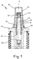
- Diaphragm valve housing 10 one not closer Diaphragm valve shown has a housing cover according to FIG. 1 12, which is penetrated by a coupling rod 14.
- the coupling rod 14 penetrates a sleeve 16.
- the with a External thread 18 provided sleeve 16 is in a in the housing cover 12 fixed threaded bushing 20 rotatably inserted such that the screwing movement causes a shift in the Sleeve 16 takes place in the direction of its longitudinal axis z.
- Stop part 22 placed, which is the one forming a stop Face 26 of the sleeve 16 is opposite.
- a sliding pad 24 instead of the slide pad 24 can also be a thrust washer made of slidable material or a roller bearing can be used.
- the parts of the sleeve 16 protruding from the housing cover 12 and the coupling rod 14 with the attached stop part 22 are with a viewing bell 30 made of transparent Material covered.
- the sight bell 30 rests on one encompassing the sleeve 16, placed on the housing cover 12 Positioning ring 28.
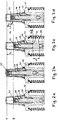
- the sleeve 16 For presetting a minimum flow cross-section of the valve the sleeve 16 by turning in the threaded sleeve 20 in their axis direction z shifted.
- the Stop part 22 moves on the end face 26 of the sleeve 16 the coupling rod 14 each by the same length Amount, which changes the minimum opening position of the valve changes accordingly.
- a stop surface 34 on the coupling rod 14 provided with the valve-side end face 32 of the sleeve 16 cooperates.
- the sleeve 16 is so far into the threaded sleeve 20th screwed in that the coupling rod 14 is lowered to a maximum and thereby the valve is closed.
- the stop part 22 is located here at a height g.
- the sleeve 16 is so far out of the threaded bushing 20 unscrewed that the coupling rod 14 is extended to the maximum and so that the valve is open to the maximum.
- the stop part 22 lies at a height o.
- Fig. 2c shows the setting option for the maximum stroke Coupling rod 14, with which the maximum open position of the valve and thus the maximum flow cross section can be limited can.
- the full stroke movement hv of the coupling rod 14 and thus the valve possible i.e. when the valve is actuated, it goes from its Closed position in its maximum possible open position.
- the Stop part 22 thus moves from the starting height g Closing position to the final height o the maximum open position.
- the maximum stroke of the coupling rod 14 and thus the valve can be limited in a simple manner by the sleeve 16 in the threaded sleeve 20 still further in the direction of the valve is turned.
- the sleeve 16 is like this screwed far out of the threaded bushing 20 that the valve is partially open in its basic position.
- the oneself resulting minimum flow cross-section of the valve shows themselves in the position of the stop part 22, which is at a height m between the height g of the closed position and the height o the maximum open position of the valve.
- the setting of the minimum flow cross section shown in FIG. 2d of the valve can also be achieved in that the stop part 22 placed on the coupling rod 14 as Nut on the coupling rod 14 designed as a threaded rod is screwed on.
- the stop part or the nut 22 on the coupling rod 14 By further screwing on the stop part or the nut 22 on the coupling rod 14 in the direction of the valve, the coupling rod 14 and thus the her coupled valve raised. Shortening the distance d between the valve-side end face 32 of the sleeve 16 and the Stop surface 34 on the coupling rod 14 can thus also by more or less unscrewing the stop part or the nut 22 can be reached on the coupling rod 14.
- any presetting of the valve from the outside to simple Way by changing the position of the sleeve 16 in the Threaded sleeve 20 or the stop member 22 on the coupling rod 14 realize.
- the respective operating position of the Valve at any time easily by the position of the sleeve 16 and the stop part 22 can be seen.
Landscapes
- Engineering & Computer Science (AREA)
- General Engineering & Computer Science (AREA)
- Mechanical Engineering (AREA)
- Indication Of The Valve Opening Or Closing Status (AREA)
- Fluid-Driven Valves (AREA)
- Preventing Unauthorised Actuation Of Valves (AREA)
- Magnetically Actuated Valves (AREA)
- Mechanically-Actuated Valves (AREA)
Description
- FC (fail close) Federkraft schliessend
- FO (fail open) Federkraft öffnend
- DA (double acting) doppelt wirkend
- Fig. 1
- einen Querschnitt durch einen Teil eines Ventilgehäuses;
- Fig. 2a-d
- den Querschnitt von Fig. 1 bei verschiedenen Betriebszuständen des Ventils.
Claims (8)
- Pneumatisch oder hydraulisch angetriebenes Ventil, insbesondere Membranventil, mit einem über eine Koppelstange (14) betätigbaren Ventilkörper, wobei die Koppelstange (14) zur Einstellung eines Mindestdurchflussquerschnitts über einen veränderbaren Anschlag (16) in der entsprechenden Position gehalten wird, und wobei die Koppelstange (14) den Gehäusedeckel (12) eines Ventilgehäuses (10) durchdringt und als Anzeiger für die Ventilstellung dient, dadurch gekennzeichnet, dass die Koppelstange (14) eine Hülse (16) durchdringt, welche Hülse (16) den veränderbaren Anschlag bildet und über ein Aussengewinde (18) in eine ortsfest mit dem Gehäusedeckel (12) verbundene Gewindebüchse (20) eingreift und durch eine Schraubbewegung in ihrer Achsenrichtung (z) verschiebbar ist, und dass am freien Ende der Koppelstange (14) ein Anschlagteil (22) festgelegt ist, das mit der dem Ventilkörper abgewandten Stirnseite (26) der Hülse (16) in Anschlag bringbar ist.
- Ventil nach Anspruch 1, dadurch gekennzeichnet, dass das Anschlagteil (22) in seiner Position an der Koppelstange (14) veränderbar festgelegt ist.
- Ventil nach Anspruch 2, dadurch gekennzeichnet, dass die Koppelstange (14) zumindest im Bereich des Anschlagteils (22) als Gewindestab ausgeführt ist und das Anschlagteil (22) ein Innengewinde aufweist, so dass die Position des Anschlagteils (22) auf der Koppelstange (14) durch eine Schraubbewegung verändert werden kann.
- Ventil nach einem der Ansprüche 1 bis 3, dadurch gekennzeichnet, dass die Koppelstange (14) ortsfest mit einer Anschlagfläche (34) verbunden ist, die als Anschlag gegen die dem Ventilkörper zugewandte Stirnseite (32) der Hülse (16) dient.
- Ventil nach einem der Ansprüche 1 bis 4, dadurch gekennzeichnet, dass das Anschlagteil (22) mit einer Gleitauflage (24) versehen ist.
- Ventil nach einem der Ansprüche 1 bis 4, dadurch gekennzeichnet, dass zwischen dem Anschlagteil (22) und der Hülse (16) eine Anlaufscheibe aus gleitfähigem Material oder ein Wälzlager angeordnet ist.
- Ventil nach einem der Ansprüche 1 bis 6, dadurch gekennzeichnet, dass der den Gehäusedeckel (12) durchdringende Teil der Koppelstange (14) mit dem Anschlagteil (22) sowie ein Teil der Hülse (16) von einer auf den Gehäusedeckel (12) aufgesetzten Sichtglocke (30) abgedeckt sind, an welcher eine Skalierung zur Hubüberwachung anbringbar ist.
- Ventil nach einem der Ansprüche 1 bis 6, dadurch gekennzeichnet, dass bei Ausfall der Steuerenergie die Hülse (16) eine Betätigung des Ventils bzw. Handnotbetätigung ermöglicht.
Applications Claiming Priority (2)
| Application Number | Priority Date | Filing Date | Title |
|---|---|---|---|
| CH01944/94A CH689310A5 (de) | 1994-06-20 | 1994-06-20 | Membranventil. |
| CH1944/94 | 1994-06-20 |
Publications (2)
| Publication Number | Publication Date |
|---|---|
| EP0688984A1 EP0688984A1 (de) | 1995-12-27 |
| EP0688984B1 true EP0688984B1 (de) | 1998-05-06 |
Family
ID=4222249
Family Applications (1)
| Application Number | Title | Priority Date | Filing Date |
|---|---|---|---|
| EP95108939A Expired - Lifetime EP0688984B1 (de) | 1994-06-20 | 1995-06-09 | Membranventil |
Country Status (7)
| Country | Link |
|---|---|
| US (1) | US5647397A (de) |
| EP (1) | EP0688984B1 (de) |
| JP (1) | JP2719533B2 (de) |
| KR (1) | KR0177867B1 (de) |
| AT (1) | ATE165903T1 (de) |
| CH (1) | CH689310A5 (de) |
| DE (1) | DE59502086D1 (de) |
Cited By (1)
| Publication number | Priority date | Publication date | Assignee | Title |
|---|---|---|---|---|
| DE10322832A1 (de) * | 2003-05-19 | 2004-12-16 | Georg Fischer Rohrleitungssysteme Ag | Vorrichtung zur Handnotbetätigung von Ventilen |
Families Citing this family (20)
| Publication number | Priority date | Publication date | Assignee | Title |
|---|---|---|---|---|
| DE19802817A1 (de) * | 1998-01-26 | 1999-08-12 | Klein Schanzlin & Becker Ag | Mit integrierter Stellungsanzeige und Hubbegrenzung ausgestattete Kappe für die Spindel einer Absperrarmatur sowie Verfahren und Vorrichtung zu deren Herstellung |
| DE10006326A1 (de) | 2000-02-12 | 2001-08-16 | Gemue Gebr Mueller Appbau Gmbh | Handantrieb für Absperrorgane |
| JP3502597B2 (ja) * | 2000-07-07 | 2004-03-02 | Smc株式会社 | 二方弁 |
| US6918407B2 (en) * | 2001-08-08 | 2005-07-19 | W. W. Offshore, Inc. | Pneumatic reset relief valve |
| US6895130B1 (en) | 2002-02-12 | 2005-05-17 | Tobi Mengle | True position sensor for diaphragm valves using reflected light property variation |
| KR20060007373A (ko) * | 2003-03-07 | 2006-01-24 | 스와겔로크 컴패니 | 조정 가능한 정지 수단이 구비된 밸브 |
| US20050150560A1 (en) * | 2004-01-08 | 2005-07-14 | Jerry Amato | Diaphragm valve |
| TW200641283A (en) * | 2005-02-18 | 2006-12-01 | Swagelok Co | Flow control device with flow adjustment mechanism |
| WO2006091710A2 (en) * | 2005-02-22 | 2006-08-31 | Swagelok Company | Valve and actuator assemblies |
| US9341281B2 (en) | 2007-02-12 | 2016-05-17 | Colt Irrigation Llc | Fluid activated flow control apparatus |
| US8397745B2 (en) | 2007-02-12 | 2013-03-19 | Colt Irrigation, LLC | Fluid activated flow control apparatus |
| US8191574B1 (en) | 2008-05-27 | 2012-06-05 | Davis Edward H | Visual indicator for air tank valve handle |
| JP5759883B2 (ja) * | 2011-12-15 | 2015-08-05 | Ckd株式会社 | 切換弁 |
| US9599286B2 (en) | 2014-01-23 | 2017-03-21 | Colt Irrigation, LLC | Fluid activated flow control apparatus |
| US10088849B2 (en) | 2014-01-23 | 2018-10-02 | Colt Irrigation, LLC | Fluid activated flow control apparatus |
| US10571937B1 (en) | 2014-01-23 | 2020-02-25 | Colt Irrigation, LLC | Valve control apparatus |
| DE202017104079U1 (de) * | 2017-07-07 | 2017-08-21 | Samson Ag | Stellantrieb für Prozessventile |
| DE102018213711A1 (de) * | 2018-08-15 | 2020-02-20 | Festo Ag & Co. Kg | Ventil |
| DE102019129059A1 (de) * | 2019-10-28 | 2021-04-29 | Grohe Ag | Ventil für eine Sanitärarmatur mit einem Membranventil und einem einstellbaren Steuerstab |
| CN114396487A (zh) * | 2021-12-31 | 2022-04-26 | 宁波宝蒂塑胶阀门有限公司 | 一种气动隔膜阀 |
Family Cites Families (11)
| Publication number | Priority date | Publication date | Assignee | Title |
|---|---|---|---|---|
| US421308A (en) * | 1890-02-11 | reynolds | ||
| US685396A (en) * | 1901-07-17 | 1901-10-29 | American Steam Heating Specialty Company | Fitting for steam heating apparatus. |
| GB682057A (en) * | 1951-07-18 | 1952-11-05 | Allan Grannenfelt | Improvements in or relating to sluice valves |
| US3175473A (en) * | 1962-05-01 | 1965-03-30 | Grinnell Corp | Spring and fluid pressure actuator |
| NL133568C (de) * | 1966-07-01 | |||
| US3946756A (en) * | 1974-05-30 | 1976-03-30 | A-T-O Inc. | Pressure control valve |
| US4099703A (en) * | 1976-10-12 | 1978-07-11 | Ideal-Aerosmith, Inc. | Self-cleaning precision metering valve |
| GB2083594A (en) | 1980-07-26 | 1982-03-24 | Schubert & Salzer Maschinen | Slide valve |
| JPS60169467U (ja) * | 1984-04-20 | 1985-11-09 | 旭有機材工業株式会社 | プラスチツク製ゲ−トバルブ |
| US5102094A (en) * | 1991-01-30 | 1992-04-07 | Marlen Research Corporation | Vacuumizer valve assembly |
| DE9207226U1 (de) | 1992-05-28 | 1992-07-30 | J. Lorch Gesellschaft & Co Kg, 7035 Waldenbuch | Membranventil |
-
1994
- 1994-06-20 CH CH01944/94A patent/CH689310A5/de not_active IP Right Cessation
-
1995
- 1995-06-09 AT AT95108939T patent/ATE165903T1/de not_active IP Right Cessation
- 1995-06-09 EP EP95108939A patent/EP0688984B1/de not_active Expired - Lifetime
- 1995-06-09 DE DE59502086T patent/DE59502086D1/de not_active Expired - Fee Related
- 1995-06-19 JP JP7151506A patent/JP2719533B2/ja not_active Expired - Fee Related
- 1995-06-19 US US08/492,395 patent/US5647397A/en not_active Expired - Fee Related
- 1995-06-20 KR KR1019950016535A patent/KR0177867B1/ko not_active Expired - Fee Related
Cited By (2)
| Publication number | Priority date | Publication date | Assignee | Title |
|---|---|---|---|---|
| DE10322832A1 (de) * | 2003-05-19 | 2004-12-16 | Georg Fischer Rohrleitungssysteme Ag | Vorrichtung zur Handnotbetätigung von Ventilen |
| DE10322832B4 (de) * | 2003-05-19 | 2006-07-13 | Georg Fischer Rohrleitungssysteme Ag | Vorrichtung zur Handnotbetätigung von Ventilen |
Also Published As
| Publication number | Publication date |
|---|---|
| KR0177867B1 (ko) | 1999-04-15 |
| CH689310A5 (de) | 1999-02-15 |
| KR960001571A (ko) | 1996-01-25 |
| JPH084940A (ja) | 1996-01-12 |
| ATE165903T1 (de) | 1998-05-15 |
| EP0688984A1 (de) | 1995-12-27 |
| US5647397A (en) | 1997-07-15 |
| DE59502086D1 (de) | 1998-06-10 |
| JP2719533B2 (ja) | 1998-02-25 |
Similar Documents
| Publication | Publication Date | Title |
|---|---|---|
| EP0688984B1 (de) | Membranventil | |
| DE4323150B4 (de) | Drehtürantrieb | |
| DE60207816T2 (de) | Türschliesser | |
| DE2649520C2 (de) | ||
| DE19950582B9 (de) | Betätigungsvorrichtung für ein drehbares Verschlussteil eines Ventils | |
| DE102014203882B4 (de) | Kolben-Zylinder-Einheit und Türscharnier mit einer Kolben-Zylinder-Einheit | |
| EP2697464A1 (de) | Schliess-scharnier | |
| EP1431496A2 (de) | Elektrohydraulischer Servotürantrieb zum Antrieb einer Tür, eines Fensters oder dergleichen | |
| DE102009036872B4 (de) | Türeinheit | |
| EP0972902B1 (de) | Türschliesser mit kompakten Abmessungen | |
| EP0816730B1 (de) | Vorrichtung zur Begrenzung der Vorspannung einer Regelfeder | |
| DE2150392A1 (de) | Regulierventil mit erleichtertem Stroemungsverlauf | |
| EP0622574A2 (de) | Betätigungsvorrichtung für ein drehbares Verschlussstück eines Ventils | |
| DE4323152C2 (de) | Drehtürantrieb | |
| DE10031403C2 (de) | Obentürschließer mit einer Gleitschienenanordnung | |
| CH641260A5 (en) | Pressure control (relief) valve for hydraulic control systems | |
| DE2362250C2 (de) | Hydraulische Hilfskraftlenkeinrichtung für Fahrzeuge | |
| DE19607878B4 (de) | Drehtürantrieb | |
| CH689055A5 (de) | Drehtuerantrieb. | |
| DE4323151C5 (de) | Drehtürantrieb | |
| DE102006059577B4 (de) | Ventil | |
| EP0074496B1 (de) | Ventilvorrichtung, insbesondere für Druckgiessmaschinen | |
| DE19524778B4 (de) | Türschließer mit einem Verdrängerkolben | |
| DE3829566A1 (de) | Kolbenantrieb | |
| DE2241551A1 (de) | Durchgangsventil |
Legal Events
| Date | Code | Title | Description |
|---|---|---|---|
| PUAI | Public reference made under article 153(3) epc to a published international application that has entered the european phase |
Free format text: ORIGINAL CODE: 0009012 |
|
| 17P | Request for examination filed |
Effective date: 19950609 |
|
| AK | Designated contracting states |
Kind code of ref document: A1 Designated state(s): AT CH DE FR GB IT LI NL |
|
| GRAG | Despatch of communication of intention to grant |
Free format text: ORIGINAL CODE: EPIDOS AGRA |
|
| 17Q | First examination report despatched |
Effective date: 19970828 |
|
| GRAG | Despatch of communication of intention to grant |
Free format text: ORIGINAL CODE: EPIDOS AGRA |
|
| GRAH | Despatch of communication of intention to grant a patent |
Free format text: ORIGINAL CODE: EPIDOS IGRA |
|
| GRAH | Despatch of communication of intention to grant a patent |
Free format text: ORIGINAL CODE: EPIDOS IGRA |
|
| GRAA | (expected) grant |
Free format text: ORIGINAL CODE: 0009210 |
|
| AK | Designated contracting states |
Kind code of ref document: B1 Designated state(s): AT CH DE FR GB IT LI NL |
|
| REF | Corresponds to: |
Ref document number: 165903 Country of ref document: AT Date of ref document: 19980515 Kind code of ref document: T |
|
| REG | Reference to a national code |
Ref country code: CH Ref legal event code: EP |
|
| GBT | Gb: translation of ep patent filed (gb section 77(6)(a)/1977) |
Effective date: 19980506 |
|
| REG | Reference to a national code |
Ref country code: CH Ref legal event code: NV Representative=s name: ROTTMANN, ZIMMERMANN + PARTNER AG |
|
| REF | Corresponds to: |
Ref document number: 59502086 Country of ref document: DE Date of ref document: 19980610 |
|
| ITF | It: translation for a ep patent filed | ||
| ET | Fr: translation filed | ||
| PLBE | No opposition filed within time limit |
Free format text: ORIGINAL CODE: 0009261 |
|
| STAA | Information on the status of an ep patent application or granted ep patent |
Free format text: STATUS: NO OPPOSITION FILED WITHIN TIME LIMIT |
|
| 26N | No opposition filed | ||
| PG25 | Lapsed in a contracting state [announced via postgrant information from national office to epo] |
Ref country code: LI Free format text: LAPSE BECAUSE OF NON-PAYMENT OF DUE FEES Effective date: 19990630 Ref country code: CH Free format text: LAPSE BECAUSE OF NON-PAYMENT OF DUE FEES Effective date: 19990630 |
|
| PG25 | Lapsed in a contracting state [announced via postgrant information from national office to epo] |
Ref country code: NL Free format text: LAPSE BECAUSE OF NON-PAYMENT OF DUE FEES Effective date: 20000101 |
|
| REG | Reference to a national code |
Ref country code: CH Ref legal event code: PL |
|
| NLV4 | Nl: lapsed or anulled due to non-payment of the annual fee |
Effective date: 20000101 |
|
| REG | Reference to a national code |
Ref country code: GB Ref legal event code: IF02 |
|
| PGFP | Annual fee paid to national office [announced via postgrant information from national office to epo] |
Ref country code: GB Payment date: 20030530 Year of fee payment: 9 |
|
| PGFP | Annual fee paid to national office [announced via postgrant information from national office to epo] |
Ref country code: AT Payment date: 20030603 Year of fee payment: 9 |
|
| PGFP | Annual fee paid to national office [announced via postgrant information from national office to epo] |
Ref country code: FR Payment date: 20030611 Year of fee payment: 9 |
|
| PGFP | Annual fee paid to national office [announced via postgrant information from national office to epo] |
Ref country code: DE Payment date: 20040604 Year of fee payment: 10 |
|
| PG25 | Lapsed in a contracting state [announced via postgrant information from national office to epo] |
Ref country code: GB Free format text: LAPSE BECAUSE OF NON-PAYMENT OF DUE FEES Effective date: 20040609 Ref country code: AT Free format text: LAPSE BECAUSE OF NON-PAYMENT OF DUE FEES Effective date: 20040609 |
|
| GBPC | Gb: european patent ceased through non-payment of renewal fee |
Effective date: 20040609 |
|
| PG25 | Lapsed in a contracting state [announced via postgrant information from national office to epo] |
Ref country code: FR Free format text: LAPSE BECAUSE OF NON-PAYMENT OF DUE FEES Effective date: 20050228 |
|
| REG | Reference to a national code |
Ref country code: FR Ref legal event code: ST |
|
| PG25 | Lapsed in a contracting state [announced via postgrant information from national office to epo] |
Ref country code: IT Free format text: LAPSE BECAUSE OF NON-PAYMENT OF DUE FEES;WARNING: LAPSES OF ITALIAN PATENTS WITH EFFECTIVE DATE BEFORE 2007 MAY HAVE OCCURRED AT ANY TIME BEFORE 2007. THE CORRECT EFFECTIVE DATE MAY BE DIFFERENT FROM THE ONE RECORDED. Effective date: 20050609 |
|
| PG25 | Lapsed in a contracting state [announced via postgrant information from national office to epo] |
Ref country code: DE Free format text: LAPSE BECAUSE OF NON-PAYMENT OF DUE FEES Effective date: 20060103 |