EP0684531A2 - Gerät und Verfahren zum Drucken eines Bildes - Google Patents
Gerät und Verfahren zum Drucken eines Bildes Download PDFInfo
- Publication number
- EP0684531A2 EP0684531A2 EP95303515A EP95303515A EP0684531A2 EP 0684531 A2 EP0684531 A2 EP 0684531A2 EP 95303515 A EP95303515 A EP 95303515A EP 95303515 A EP95303515 A EP 95303515A EP 0684531 A2 EP0684531 A2 EP 0684531A2
- Authority
- EP
- European Patent Office
- Prior art keywords
- charge
- image
- medium
- printing apparatus
- accordance
- Prior art date
- Legal status (The legal status is an assumption and is not a legal conclusion. Google has not performed a legal analysis and makes no representation as to the accuracy of the status listed.)
- Granted
Links
- 238000000034 method Methods 0.000 title claims description 59
- 238000010438 heat treatment Methods 0.000 claims abstract description 96
- 230000003472 neutralizing effect Effects 0.000 claims abstract description 90
- 230000000694 effects Effects 0.000 claims abstract description 23
- 238000012546 transfer Methods 0.000 claims abstract description 19
- 239000010408 film Substances 0.000 claims description 109
- 239000000463 material Substances 0.000 claims description 30
- 230000008569 process Effects 0.000 claims description 24
- 239000000126 substance Substances 0.000 claims description 17
- 239000010409 thin film Substances 0.000 claims description 6
- 239000004020 conductor Substances 0.000 claims description 3
- 239000010419 fine particle Substances 0.000 claims description 3
- 238000004040 coloring Methods 0.000 abstract description 7
- 230000002349 favourable effect Effects 0.000 abstract description 3
- 239000002245 particle Substances 0.000 description 40
- 238000010586 diagram Methods 0.000 description 19
- 238000002474 experimental method Methods 0.000 description 10
- 230000001276 controlling effect Effects 0.000 description 9
- 239000002033 PVDF binder Substances 0.000 description 8
- 239000003795 chemical substances by application Substances 0.000 description 8
- 238000006386 neutralization reaction Methods 0.000 description 8
- 229920002981 polyvinylidene fluoride Polymers 0.000 description 8
- 238000009825 accumulation Methods 0.000 description 7
- 230000005591 charge neutralization Effects 0.000 description 7
- 230000010287 polarization Effects 0.000 description 7
- XAGFODPZIPBFFR-UHFFFAOYSA-N aluminium Chemical compound [Al] XAGFODPZIPBFFR-UHFFFAOYSA-N 0.000 description 6
- 229910052782 aluminium Inorganic materials 0.000 description 6
- 230000007935 neutral effect Effects 0.000 description 6
- 230000000717 retained effect Effects 0.000 description 6
- 230000002269 spontaneous effect Effects 0.000 description 6
- OKTJSMMVPCPJKN-UHFFFAOYSA-N Carbon Chemical compound [C] OKTJSMMVPCPJKN-UHFFFAOYSA-N 0.000 description 5
- 229910052799 carbon Inorganic materials 0.000 description 5
- 229920000642 polymer Polymers 0.000 description 5
- 230000000007 visual effect Effects 0.000 description 5
- 229920003235 aromatic polyamide Polymers 0.000 description 4
- 239000000470 constituent Substances 0.000 description 4
- 230000003287 optical effect Effects 0.000 description 4
- 230000001105 regulatory effect Effects 0.000 description 4
- 238000001816 cooling Methods 0.000 description 3
- 238000009826 distribution Methods 0.000 description 3
- 230000005684 electric field Effects 0.000 description 3
- 230000007613 environmental effect Effects 0.000 description 3
- 230000006872 improvement Effects 0.000 description 3
- 230000002829 reductive effect Effects 0.000 description 3
- VYZAMTAEIAYCRO-UHFFFAOYSA-N Chromium Chemical compound [Cr] VYZAMTAEIAYCRO-UHFFFAOYSA-N 0.000 description 2
- 230000001680 brushing effect Effects 0.000 description 2
- 230000008859 change Effects 0.000 description 2
- 238000001704 evaporation Methods 0.000 description 2
- 230000008020 evaporation Effects 0.000 description 2
- 229920005570 flexible polymer Polymers 0.000 description 2
- 239000007788 liquid Substances 0.000 description 2
- 238000004519 manufacturing process Methods 0.000 description 2
- 238000001454 recorded image Methods 0.000 description 2
- 230000004044 response Effects 0.000 description 2
- 230000002441 reversible effect Effects 0.000 description 2
- 230000002411 adverse Effects 0.000 description 1
- 230000015572 biosynthetic process Effects 0.000 description 1
- 238000010276 construction Methods 0.000 description 1
- 238000007796 conventional method Methods 0.000 description 1
- 230000003247 decreasing effect Effects 0.000 description 1
- 230000006866 deterioration Effects 0.000 description 1
- 230000005489 elastic deformation Effects 0.000 description 1
- PCHJSUWPFVWCPO-UHFFFAOYSA-N gold Chemical compound [Au] PCHJSUWPFVWCPO-UHFFFAOYSA-N 0.000 description 1
- 239000010931 gold Substances 0.000 description 1
- 229910052737 gold Inorganic materials 0.000 description 1
- 239000011368 organic material Substances 0.000 description 1
- 238000012545 processing Methods 0.000 description 1
- 239000011347 resin Substances 0.000 description 1
- 229920005989 resin Polymers 0.000 description 1
- 230000003746 surface roughness Effects 0.000 description 1
- 238000013518 transcription Methods 0.000 description 1
- 230000035897 transcription Effects 0.000 description 1
Images


Classifications
-
- G—PHYSICS
- G03—PHOTOGRAPHY; CINEMATOGRAPHY; ANALOGOUS TECHNIQUES USING WAVES OTHER THAN OPTICAL WAVES; ELECTROGRAPHY; HOLOGRAPHY
- G03G—ELECTROGRAPHY; ELECTROPHOTOGRAPHY; MAGNETOGRAPHY
- G03G15/00—Apparatus for electrographic processes using a charge pattern
- G03G15/22—Apparatus for electrographic processes using a charge pattern involving the combination of more than one step according to groups G03G13/02 - G03G13/20
- G03G15/32—Apparatus for electrographic processes using a charge pattern involving the combination of more than one step according to groups G03G13/02 - G03G13/20 in which the charge pattern is formed dotwise, e.g. by a thermal head
- G03G15/321—Apparatus for electrographic processes using a charge pattern involving the combination of more than one step according to groups G03G13/02 - G03G13/20 in which the charge pattern is formed dotwise, e.g. by a thermal head by charge transfer onto the recording material in accordance with the image
Definitions
- the present invention relates to an image printing apparatus and, in particular, to an image printing apparatus applicable to a printer, facsimile equipment, a copying machine, an indicator board, and the like. More specifically, the present invention relates to an image printing apparatus in which an electrostatic latent image formed according to pyroelectric effect is developed with an electrically charged coloring medium so as to form an image on a printing medium.
- a pyroelectric material which generates, when heated, electric charge on surfaces thereof is employed to form an electrostatic latent image so as to obtain a visible image from the latent image by using an electrically charged coloring material, thereby printing images.
- PVDF polymeric polyvinylidene fluoride
- the image is developed with electrically charged particles of toner 80 to obtain a toner image.
- the image is then transformed onto a sheet of printing paper or the like to attain a copied image of the manuscript.
- C. Snelling has proposed a method of electrically and efficiently neutralizing electric charge appearing on a surface of a pyroelectric material according to his recognition that the quantity of opposite-polarity charge (charge density of the latent image) is substantially equal to that of neutralizing charge in the heating state.
- a thermal print stylus is employed as the means of heating the pyroelectric material.
- On a surface of the needle there is arranged an electrically conductive layer to be grounded such that the electric charge generated in the heating state is efficiently neutralized through the conductive layer.
- a belt-shaped medium 93 for keeping thereon electric charge of a latent image includes a pyroelectric layer 94 and an electrically conductive layer 95.
- a heating needle 96 Disposed on the pyroelectric layer 94 is a heating needle 96, which selectively heats a surface of the pyroelectric layer 94 according to a signal under control of a controller 98.
- a grounded conductive layer 97 Disposed on a surface of the heating needle 96 is a grounded conductive layer 97 through which charge collected on the surface of the pyroelectric layer 94 is neutralized.
- the latent image 99 is developed with toner by a developer 100 such that the developed image is transformed onto a printing medium 102 by transfer means (pyroelectric effect is used also in the transfer means according to Snelling).
- an electrically conductive layer is required to be arranged on a surface of the heating means.
- the conductive layer on the heating means cannot be uniformly brought into contact with the surface of the pyroelectric layer in a simple procedure. Namely, the printing density easily becomes non-uniform.
- the conductive layer on the heating means is brought into contact with the surface of the pyroelectric layer, the conductive or pyroelectric layer is worn due to friction therebetween, which makes it difficult to guarantee endurance and reliability of the apparatus.
- the conventional neutralizing method is attended with difficulty in obtaining a sufficiently uniform electric neutralization.
- charge neutralizing means conductive layer 47
- a pyroelectric layer 44 cannot be fully brought into contact with a pyroelectric layer 44 and hence the uniform neutralization is not easily effected.
- due to projections and depressions on surfaces respectively of the neutralizing means and pyroelectric layer it is quite difficult to satisfactorily bring the surface of the neutralizing means into that of the pyroelectric layer. Consequently, non-uniformity of contact therebetween easily appears as uneveness in the printing density.
- an intermediate tone having a uniform density cannot be easily reproduced.
- the charge neutralizing means is grounded and hence a strong electric field is missing in the neutralizing zone, leading to difficulty in attaining a high neutralizing efficiency.
- the neutralizing performance becomes insufficient and hence it is difficult to obtain a satisfactory printing density (charge density of the latent image).
- Curie temperature of PVDF which is a polymeric substance generally utilized as the pyroelectric material is about 120°C.
- the temperature of PVDF exceeds this value, the pyroelectric characteristic thereof is deteriorated or is completely vanished.
- PVDF functions with a stable characteristic at an upper-limit temperature of about 90°C.
- the heating temperature (lower-limit temperature) to record an image with the lower-most density is set to 40°C.
- the gray-scale printing is carried out with 64 levels of gradation. In this case, the range of temperature from 0 °C to 50°C is controlled in 64 sub-ranges with respect to temperature.
- an image printing apparatus comprising a latent image charge keeping medium including a pyroelectric layer, heating means for selectively heating the charge keeping medium according to a signal, and charge neutralizing means disposed to be brought into contact with or to be in the proximity of a surface of the pyroelectric layer of the charge keeping medium for being heated by the heating means, thereby neutralizing charge appearing on the charge keeping medium due to pyroelectric effect.
- the image printing apparatus in accordance with the present invention further includes developing means for visualizing with a charged toning medium an electrostatic latent image formed on the charge keeping medium and transfer means for transferring the developed image onto a printing medium.
- the charge neutralizing means includes an electrically conductive film.
- the electrically conductive film is being relatively moved, in a process of forming a latent image on the charge keeping medium or in a process of heating the charge keeping medium, relative to the heating means in a same direction in which the charge keeping medium is moved.
- the electrically conductive film includes a film configured in the form of an endless contour.
- the electrically conductive film includes a film configured in the form of a belt.
- the electrically conductive film is made of a polymeric substance to which electrically conductive fine particles are added.
- the electrically conductive film is of a laminated configuration including at least a thin film layer made of an electrically conductive material and a layer made of a polymeric substance for supporting the thin film layer.
- the electrically conductive film includes a layer made of a thermally anisotropic material having higher thermal conductivity in a direction of thickness of the layer.
- a surface of the electrically conductive film to be brought into contact with the charge keeping medium is made of an electrically conductive substance having high flexibility equivalent to a gum rigidity of 60 degrees or less.
- the heating means is a thermal head including heat producing small elements of which temperature is increased according to Joule heat.
- the heating means is a laser beam controlled according to the signal.
- the charge keeping medium includes a film configured in the form of an endless contour, the film including a pyroelectric layer and an electrically conductive layer.
- the charge keeping medium includes an electrically conductive drum and a pyroelectric layer fabricated on a surface of the drum.
- the image printing apparatus in accordance with the present invention further includes means for applying a bias voltage to the charge neutralizing means for generating an absorbing or repulsive force for excessive charge on the surface of the pyroelectric layer.
- the image printing apparatus in accordance with the present invention further includes means for sensing temperature of the heating means and means for controlling a value of the bias voltage applied to the charge neutralizing means according to data of temperature sensed by the sensing means.
- the image printing apparatus in accordance with the present invention further includes means for applying an alternating-current voltage to the charge neutralizing means.
- the voltage applying means applies, in addition to the alternating-current voltage, a direct-current voltage component to the charge neutralizing means, the direct-current voltage component being superimposed onto the alternating-current voltage.
- the voltage applying means includes sense means for sensing information of at least one of temperature in the apparatus, humidity in the apparatus, and base temperature of the heating means and voltage control means for controlling a voltage value of the direct-current voltage component according to the sensed information.
- an image printing method of printing an image by the image printing apparatus comprising the steps of subdividing data of the image into a plurality of sets of image data according to density of pixels to be recorded and controlling for each of the image data sets the bias voltage and an amount of heat produced by the heating means and achieving a plurality of times a process of forming an electrostatic latent image for each of the image data sets, thereby printing the image data having gradation levels of density.
- Fig. 3 shows constitution of a first embodiment according to the present invention.
- the image printing device of this embodiment shown in Fig. 3 includes a latent image charge keeping medium 3 including a pyroelectric layer 1, a thermal head 4 as heating means for selectively heating the medium 3 according to a signal, a conductive film 5 configured in an endless contour which is brought into contact with a surface of the pyroelectric layer 1 on the medium 3 or which is disposed in the proximity of the surface of the pyroelectric layer 1 and is heated by the thermal head so as to neutralize charge appearing on the medium 3 according to pyroelectric effect, a developing device 7 to visualize an electrostatic latent image on the medium 3 with a electrically charged toning medium, a transfer roller 12 for transferring the developed image onto a sheet of printing paper 11, and a fixing device 15 for fixing the transferred image on the printing sheet 11.
- a latent image charge keeping medium 3 including a pyroelectric layer 1, a thermal head 4 as heating means for selectively heating the medium 3 according to a signal,
- the pyroelectric layer of the charge keeping medium contains polarized charge due to spontaneous polarization.
- the surface charge is in a neutralized state. That is, for example, floating charge in the air or charge supplied from neutralizing means such as a conductive brush attaches or fixes onto the surface of the pyroelectric layer to form an electrically neutral state.
- neutralizing means such as a conductive brush attaches or fixes onto the surface of the pyroelectric layer to form an electrically neutral state.
- the polarized charge generated on the surface of the pyroelectric layer due to spontaneous polarization of the pyroelectric material has the positive polarity and a comparable amount of true effective charge having the negative polarity fixes onto the surface of the pyroelectric layer to establish an electrically neutralized state as the initial state.
- the charge keeping medium is locally heated by the heating means according to a signal.
- the state of orientation of molecules is altered to reduce the amount of polarized charge appearing on the surface of the pyroelectric layer.
- the amount of negative-polarity charge accumulated on the surface becomes excessive. Resultantly, the surface is negatively charged.
- the grounded conductive film is brought into contact with the surface of the pyroelectric layer or is in the neighborhood thereof, the excessive charge on the surface is immediately removed through the conductive film. As a result, the surface of the pyroelectric layer is neutralized again.
- the state of polarization is also restored to the original state in the pyroelectric layer.
- the surface of the pyroelectric layer has already been separated from the conductive film and hence the negative charge is insufficient on the surface. Virtually, the surface is positively charged.
- the latent image is produced with charge having a polarity reverse to that of the polarized charge of the pyroelectric layer and hence is called "latent image by opposite-polarity charge" in this specification.
- the latent image produced with the opposite-polarity charge is gradually obscured because floating charge in the air fixes onto the image, the phenomenon takes considerably a long period of time in general. Namely, the latent image is kept remained for several hours to several tens of hours in ordinary cases.
- the medium in which the latent image is generated When the medium in which the latent image is generated is brought into or is in the neighborhood of a charged toning medium, particles of the toning medium are selectively fixed onto the surface of the pyroelectric layer to thereby develop a visual image.
- the coloring medium particles fixed onto the charge keeping medium are then transferred and fixed onto a printing medium to form a desired image thereon.
- the charge keeping medium 3 is a belt of a film including two layers, namely, a pyroelectric layer 1 (about 30 micrometer ( ⁇ m) thick) and a conductive layer 2 (about 0.05 ⁇ m thick).
- the film is configured in an endless form as shown in Fig. 3.
- the layers 1 and 2 are made of PVDF and aluminum, respectively.
- the conductive layer 2 is continuously kept at a grounding potential via a conductive roller 20.
- the thermal head 4 as the heating means is a line-type thermal head generally utilized in a thermal transfer printer.
- the thermal head 4 is configured such that fine elements generating Joule heat are repeatedly arranged with a pitch of about 83 ⁇ m (300 dots/inch) along a line in the direction of width of the medium 3.
- These heating elements are selectively activated by a controller 16 in response to signals to heat the charge keeping medium 3.
- the medium heating operation is accomplished in a state in which the medium 3 and conductive film 5 are interposed between the thermal head 4 and platen roller 6.
- the thermal head 4 is not limited to the line-type thermal head used in this embodiment. Namely, there may be adopted a serial-type thermal head.
- the conductive film 5 of the embodiment is made of a heat-resistive polymer, polyaramid (about 15 ⁇ m thick). A small amount of carbon particles are added the film material to develop conductivity equivalent to 103 to 104 ohm ( ⁇ ). Thanks to addition of conductive particles to the polymer constituting the conductive film 5, there are easily attained the sufficient mechanical strength and conductivity suitable for neutralization of charge.
- the conductive film 5 When producing a latent image, the conductive film 5 is conveyed in the same direction and at the seme speed as those of the charge keeping medium 3 for the following reason. Namely, without this provision, the surface of the conductive film 5 is pushed by the pressure between the thermal head 4 and the platen roller 6 for a long period of time and there appears quite a long period of friction between the surface and the charge keeping medium 3. However, in case where a sufficient strength against friction and a satisfactory mechanical strength are provided for the conductive film 5, the conductive film 5 need not be necessarily transported as above. Namely, the film 5 may be fixedly attached onto the surface of the heating means in such a case.
- the medium 3 After the cooling is finished, the medium 3 is left standing so that the temperature thereof returns to the room temperature through the natural cooling, thereby forming a latent image with opposite-polarity charge.
- the medium 3 may be forcibly cooled or there may be employed forcible cooling means such as a heat sink.
- the latent image 17 created on the medium 3 is developed by the developer 7.
- the developer 7 operates in a developing method using the two-component magnetic brushing. That is, there is employed a developing agent 8 in which insulating and non-magnetic toner particles are mixed with magnetic carrier particles to electrically charge the toner particles through friction therebetween so as to attach the charged toner particles onto the surface of carrier particles.
- the developing agent 8 is retained on a sleeve 10 containing therein a magnet roller 9 and is thereby brought into contact with the charge keeping medium 3. In this state, the toner particles are selectively fixed onto the surface of the medium 3 according to the distribution of charge thereon, thereby obtaining a visual image.
- a transfer roller 12 applied with an appropriate voltage is pushed against the rear surface of the printing sheet 11 to electrostatically transcribe toner 18 onto a surface of the sheet 11.
- the roller 12 includes a conductive gum roller applied with a voltage of about +1 kilovolt (kV).
- a fixing apparatus 15 including a heat roller 13 and a pressure roller 14, the toner 18 is once melted on the surface of the printing sheet 11 to be fixed onto the sheet 11, thereby producing a desired record image 19.
- the latent image developing method kind of the developing agent, transcribing method of the latent image onto the printing medium, and method of fixing the image onto the printing medium are not restricted by those used in the embodiment. Namely, any other methods employed in conventional electronic photography can be also used to obtain the similar advantageous effect.
- the charge keeping medium 3 is transported again to the latent image creating section (thermal head section) to generate another latent image.
- a cleaner (not shown) is used to remove the remaining toner when necessary.
- a portion of charge of the latent image may possibly remain on the medium 3 after the toner 18 is transferred onto the sheet 11.
- a conductive brush (not shown) connected to the ground potential is brought into contact with the surface of the pyroelectric layer 1 to easily neutralize the latent image charge thereon.
- the charge keeping medium 3 is brought into contact with the conductive roller 5, the remaining charge can also be completely neutralized in this operation. Namely, a favorable picture free of influence (ghost, etc.) of the remaining charge of the latent image can be created without arranging any particular means for electrically neutralizing the latent image charge.
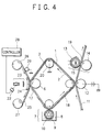
- Fig. 4 shows constitution of a second embodiment according to the present invention.
- a laser beam and a band-shaped film are adopted as the heating means and the conductive film, respectively.
- Other constituent components are the same as those of the first embodiment and hence are assigned with the same reference numerals.
- the image printing device includes a medium keeping thereon latent image charge 3 including a pyroelectric layer 1, a laser 22 and an optical system 23 collectively serving as means for selectively heating the medium 3 according to a signal, a band-shaped conductive film 25 which is brought into contact with or is disposed in the proximity of a surface of the pyroelectric layer 1 of the medium 3 and which is heated by the laser 22 to neutralize charge collected on the medium 3 due to pyroelectric effect, a developer 7 for producing a visual image with a charged toning medium according to an electrostatic latent image on the medium 3, a transfer roller 12 for transferring the developed image onto a sheet of printing paper 11, and a fixing device for fixing the transferred image onto the printing sheet 11.
- a medium keeping thereon latent image charge 3 including a pyroelectric layer 1, a laser 22 and an optical system 23 collectively serving as means for selectively heating the medium 3 according to a signal
- a band-shaped conductive film 25 which is brought into contact with or is disposed in the proximity of a
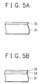
- the conductive film 25 is fabricated in a laminated configuration including a conductive layer 32 accumulated on a support layer 31 made of a heat-resistive polymer. Specifically, polyaramid (10 ⁇ m thick, free of carbon particles) and a highly flexible polymer containing carbon particles (5 ⁇ m thick) are employed for the support layer 31 and conductive layer 33, respectively.
- the conductive layer 32 is kept at a grounding potential through a conductive roller 29.
- the conductive film 25 is slightly moved from a roller 26 to a roller 27. This prevents deterioration in the characteristic of the film 25 due to friction between the film 25 and the medium 3.
- Laser light illuminated from the laser 22 under supervision of a controller 28 is irradiated onto the conductive film 25 via the optical system and support member 24. Since the support layer 31 of the film 25 is transparent with respect to the laser light, the laser light is absorbed by the conductive layer 32 to be transformed into thermal energy. Resultant heat is imparted to the medium 3 through thermal conduction to resultantly form a thermal distribution on the medium 3 according to signals. In this embodiment, the laser light is radiated directly onto the conductive layer 32 of the film 25. However, as shown in Fig. 5B, when a laser light absorbing layer 33 is additionally arranged in the conductive film 25, the heating operation can be more efficiently achieved. To effectively heat the charge keeping medium 3, the transparent support member 24 is desirably made of a material which is transparent with respect to wavelengths of laser lights and which has low thermal conductivity.
- the conductive layer 32 is made of a highly flexible polymer. This guarantees that the medium 3 is tightly attached onto the conductive layer 32. Consequently, the charge is neutralized with high efficiency and uniformity. Since the surface of the conductive film 25 to be brought into contact with the medium 3 is made of a material having a high flexibility, tightness or closeness of contact between the film 25 and medium 3 is increased, thereby improving efficiency and uniformity of electric neutralization.
- the surface material of the film 25 has desirably a gum rigidity of 60 or less.
- a latent image 17 is created thereon with reverse-polarity charge.
- printing processes as the developing, transcribing, and fixing processes used in the first embodiment.
- the conductive film 25 is in the shape of a band in the second embodiment, it is also possible to use a film configured in an endless contour as shown in the first embodiment.
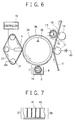
- Fig. 6 shows structure of a third embodiment according to the present invention in which the medium for keeping charge of a latent image is configured in a shape of a drum and a thermal head is adopted as the heating means. Excepting these elements, the other components of fundamental constitution of the apparatus are the same as those of the first embodiment and are assigned with the same reference numerals.
- a drum-shaped charge keeping medium 34 including a pyroelectric layer 36, a thermal head 4 for selectively heating the medium 34 according to a signal, a conductive film 37 which is configured in an endless contour and which is brought into contact with or is disposed in the neighborhood of a surface of the pyroelectric layer 36 of the medium 34 for being heated by the thermal head 4 and neutralizing charge generated on the medium 34 by pyroelectric effect, a developing device 7 for producing a visual image with a charged toning medium according to an electrostatic latent image formed on the medium 34, a transferring roller 12 for transcribing the developed image onto a sheet of printing paper 11, and a fixing device 15 for fixing the transferred image on the printing sheet 11.
- the charge keeping medium 34 includes a conductive drum 35 (aluminum) and a pyroelectric layer 36 (about 30 ⁇ m thick PVDF) fabricated thereon.
- the conductive drum 35 is kept at a ground potential.
- the conductive film 37 of the embodiment includes, as shown in Fig. 7, a thermally anisotropic film including a thermally anisotropic conductive layer 38 and an electric conductive layer 39.
- the thermally anisotropic conductive layer 38 is made of a material including a resin 40 and fine particles of gold 41 diffused thereinto under a predetermined condition, each particle having a mean diameter of 7 ⁇ m. This substance has thermal conductivity and electric conductivity only in the direction of film thickness.
- Heat produced from the thermal head 4 is efficiently imparted via the film having the thermal anisotropy effectively to the surface of the medium 34 to resultantly form on the surface of the medium 34 a temperature distrribution according to that of charge on the surface of the thermal head 4 with a high fidelity.
- the thermal head 4 when compared with a case using a thermally isotropic conductive film, there can be formed finer dots and hence the gradation printing characteristic can be improved by controlling the amount of heat produced by the thermal head 4.
- the dot diameter can be modulated at least in a range from 30 ⁇ m to 90 ⁇ m.
- a conductive layer 39 (about 0.1 ⁇ m thick aluminum film) is disposed in the electrically conductive film 37 as a common electrode to be grounded through the roller 21.
- the common electrode is arranged on the surface of the heating means and the conductive film 37 includes only the thermally anisotropic layer 38.
- the conductive film employed in the first and second embodiments may also be used as the conductive film 37 in the above embodiment.
- the surface charge can be efficiently neutralized without disposing a conductive layer directly on a surface of the heating means. This leads to improvement in resolution of heating means. Moreover, it is guaranteed there is attained an improved uniform contact between the charge keeping means and the neutralizing means with higher stability so as to achieve the image printing with higher picture quality.
- the latent image is formed thereon, namely, the medium is heated while the conductive film is being moved relative to the heating means in the same direction as the charge keeping medium.
- the charge keeping medium is fixedly attached onto the conductive member, enabling the image printing operation to be carried out with higher uniformity.
- the electrically conductive film has a multi-layer configuration including a thin-film layer made of a polymeric substance to which electrically conductive particles are added or an electrically conductive substance and a polymer layer supporting the thin-film layer. Consequently, the resultant electrically conductive film has improved mechanical strength and a characteristic suitabe for electric charge neutralization.
- the electrically conductive film includes a layer made of a substance having thermal anisotropy developing high thermal conductivity in the direction of film thickness, finer dots can be created while suppressing thermal conduction in the surface of the electrically conductive film. With this provision, a higher gradation printing characteristic is obtained and the gray-scale printing can be achieved with improved smoothness.
- the surface of the electrically conductive film brought into contact with the charge keeping medium is made of an electrically conductive material having high flexibility, namely, a gum rigidity of 60 degrees or less.
- an electrically conductive material having high flexibility namely, a gum rigidity of 60 degrees or less.
- Fig. 8 shows constitution of a fourth embodiment according to the present invention in which a thermal head and an electrically conductive layer formed on a surface of the thermal head are adopted as means for heating the charge keeping medium and charge neutralizing means, respectively.
- the image printing apparatus of the embodiment includes a medium 3 which is formed in an endless contour to keep thereon charge of a latent image, a thermal head 4, an electrically conductive layer 65, a power source 71, a developing facility 7 as developing means, a transfer roller 12 as image transcribing means, and a fixing device 15.
- the medium 3 includes a pyroelectric layer 51 having polarized charge 54 on a surface thereof due to spontaneous polarization of molecules. Initially, the surface charge is in a neutralized state. That is, floating charge existing in the air or true effective charge 53 supplied from neutralizing means such as an electrically conductive brush fixes onto the surface of the pyroelectric layer 51 to resultantly form the electrically neutralized state (Fig. 9A).
- neutralizing means such as an electrically conductive brush fixes onto the surface of the pyroelectric layer 51 to resultantly form the electrically neutralized state (Fig. 9A).
- the charge keeping medium 3 is locally heated by heating means according to a signal.
- the state of orientation of molecules is altered and hence the amount of polarized charge is decreased on the surface of the pyroelectric layer 51.
- the negative charge fixed on the surface becomes excessive.
- the surface of the pyroelectric layer is negatively charged (Fig. 9B).
- the conductive layer 52 is kept retained at a ground potential for the following reasons. Namely, the true effective charge 53 fixed onto the surface of the pyroelectric layer 51 is kept remained in a stable state and the potential of the latent image is stabilized in the subsequent image developing and transferring processes.
- Charge neutralizing means 55 is disposed to be brought into contact with or to be in the proximity of the pyroelectric layer surface such that the excessive charge appearing on the surface is neutralized by the neutralizing means 55 and hence the surface is gradually returned to the neutral state (Fig. 9C).
- a bias voltage is applied to the charge neutralizing means 55 so that an absorbing or repulsive force acts upon the excessive charge on the pyroelectric layer surface.
- Intensity of the bias voltage is set to an appropriate value according to the condition of generating the latent image (i.e. of heating the pyroelectric layer).
- a bias voltage having a polarity opposite to that of the excessive charge is applied to the neutralizing means 55.
- This causes a strong absorbing force to exert influence upon the excessive charge and hence the excessive charge is efficiently cancelled on the surface.
- a bias voltage having the same polarity as the excessive charge is applied to the neutralizing means.
- the polarized state is also restored to the original state in the pyroelectric layer.
- the surface is positively charged (Fig. 9D). That is, after the charge keeping medium is cooled, a positive-polarity latent image is formed in the heated portion thereof.
- the latent image of charge has a polarity opposite to that of (excessive) charge appearing in the heating process and hence is called "latent image by opposite-polarity charge" in this specification.
- the latent image is gradually vanished because floating charge existing in the air is collected onto the image.
- the phenomenon generally takes a long period of time, namely, the latent image is kept retained for several hours to several tens of hours.
- the charge keeping medium on which the latent image is formed When the charge keeping medium on which the latent image is formed is in the vicinity of or is brought into contact with the charged toning or coloring medium, particles of the charged toning medium are selectively fixed onto the pyroelectric layer surface so as to visualize (develop) the latent image. The toner particles fixed onto the charge keeping medium are then transferred and fixed onto the printing medium, thereby creating a desired image thereon.
- an electrically conductive layer 65 is formed as the charge neutralizing means to cover the heating section.
- a thin metallic film of aluminum or chrome having a thickness of about 1000 angstrohms is fabricated on the thermal head surface by evaporation. The film is used as the electrically conductive layer 65.
- other substances including electrically conductive organic materials may be utilized.
- a bias voltage of +300 V is applied from a power supply 71 to the conductive layer 65 so that a strong absorbing force acts upon the generated charge (having the negative polarity).
- the surface charge of the pyroelectric layer 1 is removed in a short period of time. Furthermore, the surface charge is fully cancelled even when the conductive layer 65 is not completely brought into contact with the surface of the pyroelectric layer 1.
- the excessive charge can be optimally neutralized in the process of creating a latent image.
- a bias voltage of the polarity reverse to that of exessive charge is applied to the electrically conductive layer, the neutralizing efficiency is remarkably improved. Consequently, the image can be recorded with high printing density also in a high-speed printing operation. Furthermore, even when the contact between the charge neutralizing means and the surface of the pyroelectric layer is insufficient, the surface charge can be fully neutralized. Consequently, the image can be recorded with satisfactory uniformity in printing density.
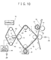
- Fig. 10 shows structure of a fifth embodiment in accordance with the present invention including a thermal head as means of heating the charge keeping medium and an electrically conductive film as charge neutralizing means.
- the constituent components other than the charge neutralizing means are the same as those of the embodiment shown in Fig. 8 and are assigned with the same reference numerals.
- the image printing apparatus of the embodiment includes a latent image charge keeping medium 3 in the form of an endless contour, a thermal head 4, an electrically conductive film 42, a temperature sensor 43, a bias voltage controller 44, a developer 7 as image developing means, a transfer roller 12 as image transcribing means, and a fixing device 15.
- the charge keeping medium 3 is fixedly attached onto the conductive film 42 by the thermal head 4 and a platen roller 6.
- the medium 3 is heated through the conductive film 42.
- the film 42 is made of a heat resistive polymer, polyaramid (about 15 ⁇ m thick). Carbon particles are slightly added to the material to develop conductivity equivalent to 103 to 104 ohm.
- the film is configured in the form of an endless belt. The latent image is produced while moving the belt 42 and the medium 3 at the same speed in the same direction.
- the pyroelectric layer 1 of the heated medium 3 On the surface of the pyroelectric layer 1 of the heated medium 3, there is collected electric charge due to pyroelectric effect. The surface charge is thereafter neutralized through the conductive film 42.
- a bias voltage is applied via a roller 45 to the conductive film 42.
- the representative temperature of the thermal head 4 is measured by the temperature sensor 43 disposed thereon. Based on the obtained temperature data, the bias voltage to be applied to the conductive film 42 is regulated by the bias voltage controller 44. That is, when the temperature of the thermal head 4 is increasing due to accumulation of heat, the bias voltage applied to the conductive film 42 is reduced (or a bias voltage having the opposite polarity is applied thereto) to minimize the charge neutralizing efficiency, thereby suppressing any excessive increase in printing density.
- a latent image 17 is formed by the reverse-polarity charge.
- a desired image 19 can be recorded on a sheet of printing paper 11 by the image printing processes including the image developing, transferring, and fixing processes shown in Fig. 8.
- the printing density is adjusted by the bias voltage.
- the effect of density adjustment by the bias voltage may also be used in other configurations. For example, it may be possible that the operator of the image printing apparatus arbitrarily adjusts the bias voltage to simply regulate image printing density.
- the charge density can be kept unchanged in the resultant latent image. Consequently, there can be provided a highly reliable image printing facility capable of producing an image with high picture quality.
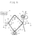
- Fig. 11 shows a sixth embodiment in accordance with the present invention.
- the image printing device of the embodiment includes a charge keeping medium 3 in the form of an endless belt, a thermal head 4 as heating means, an electrically conductive layer 65 as charge neutralizing means, a power source 61, a developing device 7, an image transfer roller 12, and a fixing device 15.
- the medium 3 includes a pyroelectric layer 51 on which polarized charge 54 is collected due to spontaneous polarization of molecules thereof.
- the surface charge is in the neutralized state. Namely, floating charge in the air or true effective charge from neutralizing means such as an electrically conductive brush fixes onto the pyroelectric layer surface to form an electrically neutral state (Fig. 14A).
- neutralizing means such as an electrically conductive brush fixes onto the pyroelectric layer surface to form an electrically neutral state (Fig. 14A).
- the charge keeping medium 3 is locally heated by the heating means 4 according to signals.
- the state of orientation of molecules is changed in the pyroelectric material to minimize the amount of polarized charge on the surface of the pyroelectric layer.
- the pyroelectric layer surface is brought into contact with or is in the neighborhood of a charge neutralizing means 55. Excessive charge generated on the surface is cancelled by the neutralizing means 55 and hence the surface becomes an electrically neutral state again (Fig. 14C).
- the neutralizing means 55 is applied with an alternating-current (ac) voltage in which the voltage value periodically varies centered on a reference voltage of 0 volt. Thanks to the ac voltage applied thereto, an oscillating electric field having a periodically changing electric field intensity is created between the charge keeping medium 3 and the charge neutralizing means 65, thereby uniformly neutralizing the charge keeping medium 3.
- ac alternating-current
- the shift of charge from the surface of the charge keeping medium e to the neutralizing means 65 and that of charge from the neutralizing means 65 to the surface of the charge keeping medium 3 are repeatedly accomplished with a short cycle so as to accordingly generate a uniformly neutralized state on the surface of the charge keeping medium 3.
- the latent image on the charge keeping medium 3 is visualized or developed with a charged toning medium and is then transferred and fixed on a printing medium such as a sheet of printing paper when necessary, thereby attained a desired image.
- the reference potential of the charge neutralizing operation can be altered by superimposing a direct-current (dc) voltage component onto the ac voltage applied to the neutralizing means. Namely, even when the heating temperature is fixed, the latent image potential can be varied by altering the dc voltage component in the voltage applied to the neutralizing means. Consequently, in case where the latent image potential is changed due to factors such as variation in the environmental temperature and increase in temperature of the heating means, the latent image potential can be kept unchanged by adjusting the magnitude of the dc voltage component.
- dc direct-current
- the charge keeping medium 3 is formed as a film including a pyroelectric layer 1 (about 100 ⁇ m thick) and an electrically conductive layer 2 (about 0.1 ⁇ m thick), the film being configured in the form of an endless-belt contour.
- the pyroelectric layer 1 and conductive layer 2 are made of PVDF and aluminum, respectively.
- the conductive layer 2 is kept at the ground potential via an electrically conductive roller 20.
- an electrically conductive layer 65 As charge neutralizing means, the layer 65 covering the heating section.
- a thin metallic film having a thickness of about 0.1 ⁇ m of aluminum or chrome is arranged on the thermal head surface by evaporation. This film is adopted as the conductive layer.
- the conductive layer on the thermal head surface there may be utilized such materials other than the metallic film of the embodiment as an electrically conductive organic substance.
- An insulating layer may be manufactured as the base of the electrically conductive layer to resultantly form a laminated construction.
- the charge is neutralized through the conductive layer 65.
- the layer 65 is applied with an ac voltage from a power supply 61.
- the ac voltage in this specification indicates a voltage of which the value periodically alters centered on a reference voltage of 0 volt.
- the conductive layer 65 is applied with an ac voltage of which the voltage varies in the form of a sine wave with an amplitude of 1.5 kV and frequency of 100 herz (Hz).
- the frequency and amplitude of the ac voltage are desirably set to 50 to 500 Hz and 1 kV or more, respectively.
- the optimal frequency and amplitude depend on materials and surface contours respectively of the neutralizing means and charge keeping medium and hence are not necessarily limited to the ranges of values described above.
- the heated medium is naturally cooled down to the room temperature to produce a latent image with the opposite-polarity charge.
- the increase in temperature of the surface of the pyroelectric layer 1 is 40°C, there is attained a latent image potential of about 900 V.
- the latent image 17 on the medium 3 is developed by the developer 7 using the two-component magnetic brushing operation.
- a developing agent 8 containing insulating and non-magnetic toner particles mixed with magnetic carrier particles so as to electrically charge the toner particles by friction therebetween.
- the agent 8 in which toner particles are fixed onto carrier particle surfaces are kept applied to a sleeve 10 with a magnet roller 9 disposed therein.
- the agent 8 is brought into contact with the charge keeping medium 3, the toner particles are selectively fixed onto the surface of the medium according to the charge distribution thereon, thereby forming a visual image.
- the medium 3 is fixed with a sheet of printing paper 11 as a printing medium.
- the transfer roller 12 then pushes a rear surface of the printing sheet 11 to electrostatically transfer toner particles onto the surface of the printing sheet 11.
- a voltage of about +1 kV is applied to the conductive gum roller to achieve the electrostatic transfer of tone particles.
- the printing sheet 11 carrying toner particles thereon is passed through the fixing facility 15 including a heat roller 13 and a pressure roller 14 such that the toner particles are once fused on the sheet surface, thereby fixing the toner on the printing sheet 11.
- the method of developing the latent image, kind of the developing agent, method of transferring toner particles onto the printing medium, and method of fixing the toner onto the printing medium are not restricted by those used in the embodiment. Namely, the similar advantageous effect can be attained according to other methods and developing agents conventionally utilized in electrophotography.
- the charge keeping medium 3 is again moved to the latent image creating section (thermal head section) to produce a subsequent latent image.
- the remaining toner particles are removed by a cleaner (not shown) when necessary.
- charge removing means such as an electrically conductive brush grounded is brought into contact with the surface of the pyroelectric layer 1 as necessary to neutralize the charge remaining on the pyroelectric layer surface.
- Fig. 12 shows a seventh embodiment in accordance with the present invention. Excepting that an electrically conductive film is adopted as the charge neutralizing means, the constituent components are substantially the same as those of the sixth embodiment and are assigned with the same reference numerals.
- the image printing device of the embodiment includes a latent image charge keeping medium 3 in the form of an endless belt, a thermal head 4 as heating means, an electrically conductive layer 82, a temperature sensor 83, a voltage controller 84, an image developing device 7, a transfer roller 12, and a fixing device 15.
- the medium 3 is closely attached onto the conductive film 82 by the thermal head 4 and platen roller 6 and is heated via the film 82.
- the conductive film 82 is about 15 ⁇ m thick and is made of polyaramid, which is a heat resistive polymeric material. Carbon particles are slightly added to the material to attain conductivity of 103 to 104 ohm.
- the film is configured in the form of an endless belt. The conductive film 82 and the medium 3 are transported at the same speed in the same direction to produce a latent image on the medium 3.
- the pyroelectric layer 1 On the surface of the pyroelectric layer 1 thus heated, electric charge is collected due to pyroelectric effect. The charge is neutralized through the conductive film 82.
- the film 82 is applied via roller 85 with a pulsated voltage in which an ac voltage component is superimposed onto a dc voltage component.
- the ac voltage component has an amplitude of 1.5 kV and a frequency of 100 Hz and the dc voltage component has a voltage value varied in a range from -200 V to +200 V by the voltage controller 84 according to the base temperature of the thermal head 4 measured by the temperature sensor 83. With the control operation, the potential of the obtained latent image is kept retained at a fixed voltage.
- Fig. 13 shows in a block diagram the configuration of the voltage controller 84.
- the sensor 83 includes a sensor 231 for sensing the base temperature of the thermal head 4 and sensors 232 and 233 for respectively measuring temperature and humidity in the apparatus. According to information of temperature and humidity sensed by the sensors 231 to 233, there are generated control signals to be delivered respectively to analog-to-digital (A/D) convertors 241 to 243. The resultant digital signals are fed to a central processing unit (CPU) 244. In response to the received control signals, the CPU 244 produces a signal to regulate a dc component and then sends the signal to a digital-to-analog (D/A) convertor 245.
- CPU central processing unit
- the obtained analog signal is transmitted to a dc power source 246, which in turn produces a dc voltage having a controlled value.
- the dc voltage is added to an ac voltage generated from an ac power source 247 such that the obtained voltage is sent to the roller 85.
- the surface potential of the pyroelectric layer 1 is generally shifted due to the applied heat (equivalent to 10°C increase in the temperature of the thermal head 4; about 220 V in this embodiment) when the dc voltage component is not superimposed onto the ac voltage component.
- the applied heat equivalent to 10°C increase in the temperature of the thermal head 4; about 220 V in this embodiment
- the dc-voltage component of the pulsated voltage applied to the charge neutralizing means is set to a polarity opposite to that of the latent image and the magnitude of the dc voltage component is regulated to cancel the increased portion of the surface potential due to accumulated heat, thereby preventing the shift of surface potential above. This enables the latent image potential to be kept retained in any cases.
- the printing operation can be achieved with a fixed printing density even when the base temperature of the heating means is altered. This leads to a homogenous density in the image printing and makes it possible to conduct the continuous printing in a stable state.
- the control method may also be utilized to compensate for temperature in the apparatus.
- humidity in the apparatus also exercises adverse influence upon the charging and transferring characteristics of toner particles. To remove the above influence, it is effective to control the dc voltage component according to the sensed humidity in the apparatus.
- the operator of the apparatus is allowed to arbitrarily regulate magnitude of the dc voltage component, the density of recorded images can be simply adjusted by the operator.
- the reference potential of the latent image can be controlled by regulating magnitude of the dc voltage component of the pulsated voltage applied to the charge neutralizing means. This facilitates highly accurate compensation for the change in image density due to variation in the environmental temperature and heat accumulation in the heating means.
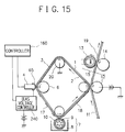
- Fig. 15 shows in a block diagram an alternative embodiment of the image printing device in which printing pixel density is modulated by controlling the amount of heat produced from the heating means and the bias voltage of the charge neutralizing means.
- image data is classified into a plurality of groups according to density such that the bias voltage value of the charge neutralizing means is stepwise varied correspondingly to the classification steps, thereby improving the gradation printing characteristic.
- the bias voltage takes two values in a two-step operation to control 64 gradation steps.
- image data is subdivided into two groups according to density, namely, image data groups respectively related to gradation levels 1 to 32 and gradation levels 33 to 64, respectively.
- a bias voltage V1 is applied to the conductive layer 65 as charge neutralizing means so that the first density is attained when the heating element is set to a lower-limit temperature of 40°C by a bias voltage controller 240 and the 32nd density is obtained when the element is heated to an upper-limit temperature of 90°C by the bias voltage controller 240.
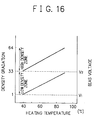
- a controller 160 to accomplish processes of generating a latent image and developing and transferring the latent image so as to record the image on a sheet of printing paper (a lower-density zone of Fig. 16).
- the bias voltage is varied to V2 so that the 33rd density is attained when the heating element is set to a lower-limit temperature and the 64th density is obtained when the element is heated to the upper-limit temperature.
- Image data of the higher-density group is then subjected to the printing process to superimpose the resultant image onto the image beforehand produced on the printing sheet (a higher-density zone of Fig. 16).
- the image data is classified into a plurality of groups according to density to produce the image a plurality of printing operations while applying a bias voltage to the charge neutralizing means according to the groups.
- the dynamic temperature range can be substantially expanded to accomplish the gray-scale printing with a larger number of gradation steps.
- the temperature control precision is represented as ⁇ 0.8°C. Namely, thanks to the image data classification, the required temperature precision can be reduced to half that of the case in which the image data is not classified. With this provision, the gradation levels can be controlled with an improved stability.
- the gradation printing characteristic can be further improved.
- the printing method of the embodiment is disadvantageous with respect to the printing speed.
- the method is quite advantageous when a high picture quality is required in the image printing operation.
- the printing procedure is not restricted by that of the embodiment.
- the heating and charge neutralizing methods Namely, only the latent image creating process may be carried out in several operation steps, whereas each of the developing and transferring processes is carried out in one operation step.
- the multi-level gradation printing can be conducted with high stability and hence there can be attained a gray-scale record image having favorable smoothness in printing density.
- the latent image charge keeping medium is configured in the form of a belt in the embodiments.
- the similar advantageous effect can also be attained by using the medium in any other forms, for example, those of a drum and flat plate.
- the transfer and fixing steps of the toning medium onto the printing medium may be dispensed with.
- the present invention is also applicable to apparatuses such as an indication board in which the toning medium is temporarily kept retained on the printing medium or latent image charge keeping medium so as to display information thereon for a predetermined period of time.
- coloring particles i.e., powdered toner particles
- any other coloring media such as a liquid toner and a liquid ink.
Landscapes
- Physics & Mathematics (AREA)
- General Physics & Mathematics (AREA)
- Electrophotography Using Other Than Carlson'S Method (AREA)
- Printers Or Recording Devices Using Electromagnetic And Radiation Means (AREA)
- Thermal Transfer Or Thermal Recording In General (AREA)
- Electronic Switches (AREA)
Priority Applications (1)
| Application Number | Priority Date | Filing Date | Title |
|---|---|---|---|
| EP98121034A EP0902338B1 (de) | 1994-05-24 | 1995-05-24 | Gerät und Verfahren zum Drucken eines Bildes |
Applications Claiming Priority (6)
| Application Number | Priority Date | Filing Date | Title |
|---|---|---|---|
| JP10884894A JP2606584B2 (ja) | 1994-05-24 | 1994-05-24 | 画像記録装置 |
| JP10884894 | 1994-05-24 | ||
| JP108848/94 | 1994-05-24 | ||
| JP129986/94 | 1994-06-13 | ||
| JP12998694 | 1994-06-13 | ||
| JP12998694 | 1994-06-13 |
Related Child Applications (1)
| Application Number | Title | Priority Date | Filing Date |
|---|---|---|---|
| EP98121034A Division EP0902338B1 (de) | 1994-05-24 | 1995-05-24 | Gerät und Verfahren zum Drucken eines Bildes |
Publications (3)
| Publication Number | Publication Date |
|---|---|
| EP0684531A2 true EP0684531A2 (de) | 1995-11-29 |
| EP0684531A3 EP0684531A3 (de) | 1996-04-17 |
| EP0684531B1 EP0684531B1 (de) | 2000-02-16 |
Family
ID=26448660
Family Applications (2)
| Application Number | Title | Priority Date | Filing Date |
|---|---|---|---|
| EP98121034A Expired - Lifetime EP0902338B1 (de) | 1994-05-24 | 1995-05-24 | Gerät und Verfahren zum Drucken eines Bildes |
| EP95303515A Expired - Lifetime EP0684531B1 (de) | 1994-05-24 | 1995-05-24 | Gerät und Verfahren zum Drucken eines Bildes |
Family Applications Before (1)
| Application Number | Title | Priority Date | Filing Date |
|---|---|---|---|
| EP98121034A Expired - Lifetime EP0902338B1 (de) | 1994-05-24 | 1995-05-24 | Gerät und Verfahren zum Drucken eines Bildes |
Country Status (3)
| Country | Link |
|---|---|
| US (1) | US5660486A (de) |
| EP (2) | EP0902338B1 (de) |
| DE (2) | DE69523641T2 (de) |
Cited By (1)
| Publication number | Priority date | Publication date | Assignee | Title |
|---|---|---|---|---|
| US6108016A (en) * | 1997-09-25 | 2000-08-22 | Nec Corporation | Image recording device which conducts image formation by development with coloring system |
Families Citing this family (5)
| Publication number | Priority date | Publication date | Assignee | Title |
|---|---|---|---|---|
| JP3176245B2 (ja) * | 1995-03-23 | 2001-06-11 | シャープ株式会社 | インクジェットヘッド |
| JPH09254442A (ja) * | 1996-03-19 | 1997-09-30 | Sharp Corp | 像形成装置 |
| US6158346A (en) * | 1998-06-22 | 2000-12-12 | The Penn State Research Foundation | Electronic printing of non-planar macro and micro devices |
| US6543946B2 (en) * | 2001-07-06 | 2003-04-08 | Alps Electric Co., Ltd. | Combination printer |
| JP2008225344A (ja) * | 2007-03-15 | 2008-09-25 | Oki Data Corp | 電子装置及び画像形成装置 |
Citations (4)
| Publication number | Priority date | Publication date | Assignee | Title |
|---|---|---|---|---|
| US3824098A (en) | 1972-06-23 | 1974-07-16 | Bell Telephone Labor Inc | Pyroelectric copying device |
| US3935327A (en) | 1973-08-06 | 1976-01-27 | Minnesota Mining And Manufacturing Company | Copying using pyroelectric film |
| JPS56158350A (en) | 1980-05-10 | 1981-12-07 | Nippon Telegr & Teleph Corp <Ntt> | Recording method |
| US5185619A (en) | 1991-04-26 | 1993-02-09 | Xerox Corporation | Electrostatic printing method and apparatus employing a pyroelectric imaging member |
Family Cites Families (6)
| Publication number | Priority date | Publication date | Assignee | Title |
|---|---|---|---|---|
| US3899969A (en) * | 1973-08-06 | 1975-08-19 | Minnesota Mining & Mfg | Printing using pyroelectric film |
| US3992204A (en) * | 1973-08-06 | 1976-11-16 | Minnesota Mining And Manufacturing Company | Method and medium for producing electrostatic charge patterns |
| US4106933A (en) * | 1975-06-18 | 1978-08-15 | Minnesota Mining And Manufacturing Company | Piezoelectric method and medium for producing electrostatic charge patterns |
| JPH02269065A (ja) * | 1988-12-23 | 1990-11-02 | Canon Inc | 熱記録方式および前記熱記録方式を用いる記録装置 |
| US5153615A (en) * | 1991-04-26 | 1992-10-06 | Xerox Corporation | Pyroelectric direct marking method and apparatus |
| US5353105A (en) * | 1993-05-03 | 1994-10-04 | Xerox Corporation | Method and apparatus for imaging on a heated intermediate member |
-
1995
- 1995-05-23 US US08/447,798 patent/US5660486A/en not_active Expired - Lifetime
- 1995-05-24 DE DE69523641T patent/DE69523641T2/de not_active Expired - Fee Related
- 1995-05-24 EP EP98121034A patent/EP0902338B1/de not_active Expired - Lifetime
- 1995-05-24 EP EP95303515A patent/EP0684531B1/de not_active Expired - Lifetime
- 1995-05-24 DE DE69515082T patent/DE69515082T2/de not_active Expired - Fee Related
Patent Citations (5)
| Publication number | Priority date | Publication date | Assignee | Title |
|---|---|---|---|---|
| US3824098A (en) | 1972-06-23 | 1974-07-16 | Bell Telephone Labor Inc | Pyroelectric copying device |
| US3935327A (en) | 1973-08-06 | 1976-01-27 | Minnesota Mining And Manufacturing Company | Copying using pyroelectric film |
| JPS56158350A (en) | 1980-05-10 | 1981-12-07 | Nippon Telegr & Teleph Corp <Ntt> | Recording method |
| US5185619A (en) | 1991-04-26 | 1993-02-09 | Xerox Corporation | Electrostatic printing method and apparatus employing a pyroelectric imaging member |
| JPH05134506A (ja) | 1991-04-26 | 1993-05-28 | Xerox Corp | 焦電気式像形成方法および装置 |
Non-Patent Citations (1)
| Title |
|---|
| J. G. BERGMAN ET AL, APPLIED PHYSICS LETTERS, vol. 21, no. 10, 1972, pages 497 - 499 |
Cited By (1)
| Publication number | Priority date | Publication date | Assignee | Title |
|---|---|---|---|---|
| US6108016A (en) * | 1997-09-25 | 2000-08-22 | Nec Corporation | Image recording device which conducts image formation by development with coloring system |
Also Published As
| Publication number | Publication date |
|---|---|
| DE69515082D1 (de) | 2000-03-23 |
| EP0902338B1 (de) | 2001-10-31 |
| EP0684531A3 (de) | 1996-04-17 |
| DE69523641D1 (de) | 2001-12-06 |
| EP0902338A1 (de) | 1999-03-17 |
| US5660486A (en) | 1997-08-26 |
| DE69515082T2 (de) | 2000-10-12 |
| EP0684531B1 (de) | 2000-02-16 |
| DE69523641T2 (de) | 2002-07-11 |
Similar Documents
| Publication | Publication Date | Title |
|---|---|---|
| US5966151A (en) | Image forming apparatus | |
| US5455668A (en) | Electrostatographic single-pass multiple-station printer for forming an image on a web | |
| US20070015071A1 (en) | Image forming apparatus for forming a color image, and image forming method for forming a color image | |
| US5628043A (en) | Image forming apparatus | |
| EP0510963B1 (de) | Verfahren und Gerät zum Drucken | |
| EP0684531B1 (de) | Gerät und Verfahren zum Drucken eines Bildes | |
| JPH08262924A (ja) | 記録装置及び記録方法 | |
| EP0401749A2 (de) | Nassaufnahmegerät | |
| JP2005106920A (ja) | 画像形成装置 | |
| EP0687963B1 (de) | Bildaufzeichnungsgerät | |
| JP2005106919A (ja) | 画像形成装置 | |
| JP2606584B2 (ja) | 画像記録装置 | |
| EP0482867A2 (de) | Entwicklungsgerät | |
| JPH0862952A (ja) | 画像記録装置および画像記録方法 | |
| US6056390A (en) | Image forming apparatus wherein the velocity of the toner supporting medium is higher than recording medium transport velocity | |
| JP4588864B2 (ja) | 捻れ配置とされたイメージ形成用一次部材から中間転写部材へとトナーを転写するための方法および装置 | |
| JP2885276B2 (ja) | 画像記録装置 | |
| JPH1035001A (ja) | 記録装置 | |
| JP2795261B2 (ja) | 画像記録装置 | |
| JP2606607B2 (ja) | 潜像電荷保持媒体 | |
| JPH02185451A (ja) | 画像記録方法 | |
| JP2725656B2 (ja) | 画像記録装置 | |
| JPH07148966A (ja) | パウダージェット画像形成装置における印字ヘッド | |
| JPH01281462A (ja) | 画像形成装置 | |
| JPH08241013A (ja) | 印刷装置および印刷方法 |
Legal Events
| Date | Code | Title | Description |
|---|---|---|---|
| PUAI | Public reference made under article 153(3) epc to a published international application that has entered the european phase |
Free format text: ORIGINAL CODE: 0009012 |
|
| AK | Designated contracting states |
Kind code of ref document: A2 Designated state(s): DE GB |
|
| PUAL | Search report despatched |
Free format text: ORIGINAL CODE: 0009013 |
|
| AK | Designated contracting states |
Kind code of ref document: A3 Designated state(s): DE GB |
|
| 17P | Request for examination filed |
Effective date: 19960328 |
|
| 17Q | First examination report despatched |
Effective date: 19971230 |
|
| GRAG | Despatch of communication of intention to grant |
Free format text: ORIGINAL CODE: EPIDOS AGRA |
|
| GRAG | Despatch of communication of intention to grant |
Free format text: ORIGINAL CODE: EPIDOS AGRA |
|
| GRAG | Despatch of communication of intention to grant |
Free format text: ORIGINAL CODE: EPIDOS AGRA |
|
| GRAH | Despatch of communication of intention to grant a patent |
Free format text: ORIGINAL CODE: EPIDOS IGRA |
|
| GRAH | Despatch of communication of intention to grant a patent |
Free format text: ORIGINAL CODE: EPIDOS IGRA |
|
| GRAA | (expected) grant |
Free format text: ORIGINAL CODE: 0009210 |
|
| AK | Designated contracting states |
Kind code of ref document: B1 Designated state(s): DE GB |
|
| REF | Corresponds to: |
Ref document number: 69515082 Country of ref document: DE Date of ref document: 20000323 |
|
| EN | Fr: translation not filed | ||
| PLBE | No opposition filed within time limit |
Free format text: ORIGINAL CODE: 0009261 |
|
| STAA | Information on the status of an ep patent application or granted ep patent |
Free format text: STATUS: NO OPPOSITION FILED WITHIN TIME LIMIT |
|
| 26N | No opposition filed | ||
| REG | Reference to a national code |
Ref country code: GB Ref legal event code: IF02 |
|
| PGFP | Annual fee paid to national office [announced via postgrant information from national office to epo] |
Ref country code: DE Payment date: 20070517 Year of fee payment: 13 |
|
| PGFP | Annual fee paid to national office [announced via postgrant information from national office to epo] |
Ref country code: GB Payment date: 20070523 Year of fee payment: 13 |
|
| GBPC | Gb: european patent ceased through non-payment of renewal fee |
Effective date: 20080524 |
|
| PG25 | Lapsed in a contracting state [announced via postgrant information from national office to epo] |
Ref country code: DE Free format text: LAPSE BECAUSE OF NON-PAYMENT OF DUE FEES Effective date: 20081202 |
|
| PG25 | Lapsed in a contracting state [announced via postgrant information from national office to epo] |
Ref country code: GB Free format text: LAPSE BECAUSE OF NON-PAYMENT OF DUE FEES Effective date: 20080524 |