EP0683084A2 - Energieabsorbierende Zwischenwelle - Google Patents
Energieabsorbierende Zwischenwelle Download PDFInfo
- Publication number
- EP0683084A2 EP0683084A2 EP94306998A EP94306998A EP0683084A2 EP 0683084 A2 EP0683084 A2 EP 0683084A2 EP 94306998 A EP94306998 A EP 94306998A EP 94306998 A EP94306998 A EP 94306998A EP 0683084 A2 EP0683084 A2 EP 0683084A2
- Authority
- EP
- European Patent Office
- Prior art keywords
- shaft
- tube
- cross
- small
- section portion
- Prior art date
- Legal status (The legal status is an assumption and is not a legal conclusion. Google has not performed a legal analysis and makes no representation as to the accuracy of the status listed.)
- Granted
Links
Images


Classifications
-
- B—PERFORMING OPERATIONS; TRANSPORTING
- B62—LAND VEHICLES FOR TRAVELLING OTHERWISE THAN ON RAILS
- B62D—MOTOR VEHICLES; TRAILERS
- B62D1/00—Steering controls, i.e. means for initiating a change of direction of the vehicle
- B62D1/02—Steering controls, i.e. means for initiating a change of direction of the vehicle vehicle-mounted
- B62D1/16—Steering columns
- B62D1/18—Steering columns yieldable or adjustable, e.g. tiltable
- B62D1/19—Steering columns yieldable or adjustable, e.g. tiltable incorporating energy-absorbing arrangements, e.g. by being yieldable or collapsible
- B62D1/192—Yieldable or collapsible columns
Definitions
- the present invention relates to an energy absorbing intermediate shaft which is built into a steering system of an automobile in order to transmit the movement of a steering wheel to a steering gear.
- a steering system for an automobile has constitution shown in Fig. 9.
- a steering wheel 2 is fixed to the upper end of a steering shaft 1, and a steering column 3 is fixed under an instrument panel 6 with an upper bracket 4 and a lower bracket 5.
- Said steering shaft 1 is rotatably set through the steering column 3.
- the lower end of the steering shaft 1 which protrudes from the lower open end of the steering column is connected via a first universal joint 7 with the upper end of an intermediate shaft 8. Further, the lower end of the intermediate shaft 8 is connected via a second universal joint 9 with the input shaft 10 of a steering gear (not shown).
- the rotation of the steering wheel 2 is transmitted through the steering shaft 1 inserted through the steering column 3, the first universal joint 7, the intermediate shaft 8, the second universal joint 9, the input shaft 10, and finally, to the steering gear, thereby giving a steering angle to wheels.
- the steering column 3, the steering shaft 1 and the intermediate shaft 8 are of energy absorbing type which, when given a bump, absorb the energy of the bump and shorten their overall lengths in order to protect the driver at the time of a car crash.
- Japanese Laid-Open Patent Appln. No. 3-79472 discloses one of the typical energy absorbing intermediate shaft.
- This typical energy absorbing intermediate shaft disclosed the above Laid-Open Patent consists of four components which are assembled together, as shown in Fig. 10. One end (the left end in Fig. 10) of a shaft 11 and a yoke 12 which constitutes a universal joint are welded together. On the periphery near the other end of the shaft 11, male splines 13 are formed. And two concave grooves 14a and 14b are formed around the periphery on which said male splines 13 are formed.
- female splines 16 are formed on the inner periphery of a connection tube 15, which has three through holes 17a, 17b and 17c penetrating from the inner periphery to the outer periphery of the connecting tube 15. These through holes are separately aligned in the axial direction, wherein the distance between the through holes 17a and 17b is the same as the distance between the above-mentioned grooves 14a and 14b.
- male splines 19 are formed on the periphery of a connecting shaft 18. And two grooves 14c and 14d are formed around the periphery on which the male splines 19 are formed.
- One end of a tube 20 is an open end, while the other end thereof and a yoke 21 which constitutes another universal joint are welded together.
- the tube 20 also has a through hole 17d penetrating from the inner periphery to the outer periphery of the tube 20.
- the distance between the through hole 17d and the above-mentioned through hole 17c when said connecting tube 15 attaches against the tube 20 is the same as the distance between the grooves 14c and 14d formed around the periphery of the connecting shaft 18.
- a clearance A between the right end face of the shaft 11 and the left end face of the connecting shaft 18 and a clearance B between the right end face of the connecting shaft 18 and the end face of the yoke 21 are formed when the components 11, 15, 18 and 20 are assembled together as described above.
- the connecting shaft 18 which connects the connecting tube 15 with the tube 20 not only transmits torque between the tubes 15 and 20 but also prevents the contact position of the tubes 15 and 20 from bending.
- the shaft 11 and the connecting shaft slip off and separate from each other. And after that, the shaft 11 does not push backwards the connecting shaft 18 nor the tube 20. Accordingly, even if the second universal joint 9 is further pushed backwards at the time of the car crash, the first universal joint 7 is not pushed backwards. Thus, as the steering wheel 2 does not protrude toward the driver, it can not hurt the driver.
- the shaft 11 and the connecting shaft 18 since two separately prepared shaft members, that is, the shaft 11 and the connecting shaft 18, constitute the shaft, at least three fixing points should be provided in order to fixedly connect the shafts 11 and 18 with the connecting tube 15 and the tube 20. And in order to provide said fixing points, the shafts 11 and 18 should have certain length of engagement with the tubes 15 and 20. In short, when more fixing force is required, the overall length of the intermediate shaft 8 becomes longer. In such a case, troubles arise. For example, it becomes difficult to arrange the intermediate shaft 8 between the first and second universal joints and obtain sufficient clearances for collapse inside the intermediate shaft 8.
- the object of the present invention is to provide an energy absorbing intermediate shaft which consists of less components and whose assembly operation is simplified. Thus, the manufacturing cost thereof can be reduced.
- the energy absorbing intermediate shaft comprises: a tube; a shaft which is inserted in the tube from the open end thereof and fixedly set thereto so as not to rotate inside the tube; and a displacement restricting portion which is formed between said shaft and said tube so that the shaft and the tube can shift in the axial direction only when strong force in the axial direction is given.
- the energy absorbing intermediate shaft further comprises: a stopper portion which is formed at the other end of said tube in order to restrict the amount of insertion of said shaft into the tube; a small-cross-section portion formed in the intermediate part, which is not inserted in the tube, of the shaft; and a reinforcing member which is provided around the shaft so as to entirely cover said small-cross-section portion and which can slide in the axis direction, wherein the length of the tube is determined so that the open end of the tube comes to the position which coincides with said small-cross-section portion when the end portion of the shaft bumps against said stopper portion.
- the reinforcing member normally covering the small-cross-section portion in the middle part of the shaft prevents the shaft from bending at said small-cross-section portion.
- the shaft bends at its small-cross-section portion so as to prevent impact force given through the front end of the energy absorbing intermediate shaft from being transmitted toward the rear end of the intermediate shaft.
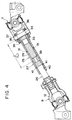
- Fig. 1 is a cross-sectional view showing an embodiment according to the present invention.
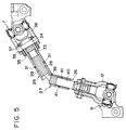
- Fig. 2 is a cross-sectional view showing the same embodiment built into a steering system.
- Fig. 3 is a cross-sectional view showing the first stage of the state of the intermediate shaft at the time of a car crash.
- Fig. 4 is a cross-sectional view showing the second stage of the state of the same.
- Fig. 5 is a cross-sectional view showing the last stage of the state of the same.
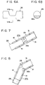
- Figs. 6A and 6B show another example of the small-cross-section portion in the middle part of the shaft, wherein Fig. 6A is a side view and Fig. 6B is a cross-sectional view cut and seen as indicated by the arrows VIB in Fig. 6A.
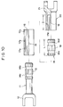
- Fig. 7 is a cross-sectional view of another example of the shape of the cover tube, which is shown in the second stage of the state as in Fig. 4.
- Fig. 8 is a cross-sectional view showing the cover tube shown in Fig. 7 in the last stage of the state as in Fig. 5.
- Fig. 9 is a side view showing an example of a steering system to which the energy absorbing intermediate shaft according to the present invention is applied.
- Fig. 10 is a partial cross-sectional view showing components of a typical intermediate shaft before assembly.
- Fig. 11 is a partial cross-sectional view showing the components shown in Fig. 10 after assembly.
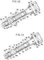
- Fig. 12 is a side view showing the longitudinal cross-section of the middle part of another embodiment according to the present invention, which is in the state corresponding to that of Fig. 2.
- Fig. 13 is a side view showing the same in the state corresponding to that of Fig. 3.
- Fig. 14 is a side view showing the same in the state corresponding to that of Fig. 4.
- Fig. 15 is a side view showing the same in the state corresponding to that of Fig. 5.
- the energy absorbing intermediate shaft of the present invention consists of a tube 25, a shaft 26 and a cover tube serving as a reinforcing member.
- the tube 25 On the inner periphery near one end (left end in Fig. 1) of the tube 25, female splines 28 are formed.
- female splines 28 On the outer periphery near one end (right end in Fig. 1) of the shaft 26, male splines 29 are formed.
- the shaft 26 is inserted into the tube 25 from said open end of the tube 25, when the female splines 28 and the male splines 29 are engaged with each other.
- a concave groove 30 is formed around the outer periphery near the right end of said shaft 26, while through holes 31 are formed in the middle portion of the tube 25 so as to correspond to the groove 30.
- a displacement restricting portion 33 is formed by injecting synthetic resin 32 via two through holes 31 into the groove 30. The displacement restricting portion 33 allows the shaft 26 to shift in the axial direction in the tube 25 only when strong force in the axial direction is given to said members 25 and 26. In the embodiment shown in the drawings, when the shaft 26 is pushed in the axial direction (rightwards in Fig. 1) into the tube 25 after stuffing the synthetic resin 32, the synthetic resin is torn and broken between the through holes 31 and the groove 30.
- the displacement restricting portion 33 restricts displacement between the tube 25 and the shaft 26 only by means of frictional force of the synthetic resin 32 acting between the inner periphery of the tube 25 and the outer periphery of the shaft 26.
- a pin 34 is fixedly set, which serves as the stopper portion for restricting the amount of insertion of the shaft 26 into the tube 25. Both end of the pin 34 protrude from the outer periphery near the right end of the tube 25, and are loosely inserted through round holes 37 formed in a buffer tube 35 as well as round holes 38 formed in a yoke 36 which constitutes a first universal joint 7.
- a small-cross-section portion 39 is formed in the intermediate part, which is not inserted in the tube 25, of the shaft 26.
- the diameter of the small-cross-section portion 39 is considerably smaller than that of the other part of the shaft 26.
- the above-mentioned male splines 29 are extended over both sides of the small-cross-section portion 39.
- the cover tube 27 is positioned so as to entirely cover the small-cross-section portion 39.
- a yoke 12 of a second universal joint 9 is fixedly set to the left end of the shaft 25, while the yoke 36 of a first universal joint 7 is supported via the buffer tube 35 around the right end of the tube 25.
- torque when torque is small, it is transmitted between the tube 25 and the yoke 12 through the buffer tube.
- torque when the torque is large, it is transmitted by means of engagement of both ends of the pin 34 with the inner surfaces of respective round holes 38.
- the energy absorbing intermediate shaft according to the present invention having the above-mentioned constitution is positioned on the slant, as shown in Fig. 2, wherein one end thereof (the front end with respect to a car body) is connected via the second universal joint 9 with an input shaft 10 (see Fig. 9) of a steering gear and the other end (the rear end) is connected via the first universal joint 7 with a steering shaft 1 (Fig. 9).
- the rotational motion of the steering shaft 1 is transmitted through the first adjustable joint 7 to the tube 25, and further through the shaft 26 to the second universal joint 9, which, in turn, rotates the input shaft 10 in order to give a desirable steering angle to front wheels.
- the shaft 26 receives torque. But, since the cover tube 27 is supported by the intermediate part of the shaft 26 in order to cover the small-cross-section portion 39, and since the female splines 40 on the inner periphery of the cover tube 27 are engaged with the male splines 29 on the outer periphery of the shaft 26, the small-cross-section portion 39 does not receive excessive stress nor is broken. In addition, since the synthetic resin 42 is stuffed around the small-cross-section portion 39 and further the cover tube 27 covers the synthetic resin 42, the shaft 26 does not bend at the small-cross-section portion 39 even if force which would otherwise bend the shaft 26 is given to the shaft 26.
- the shaft 26 in the above state further receives the compressive force in the axial direction, the shaft 26 bends at the small-cross-section portion 39, as shown in Fig. 5, thereby preventing impact force given from the second universal joint 9 to the front end of the energy absorbing intermediate shaft from being transmitted to the first universal joint attached to the rear end of the intermediate shaft.
- the synthetic resin 42 stuffed around the small-cross-section portion 39 is smashed and falls down when the shaft 26 bends at the small-cross-section portion 39.
- the shape of the small-cross-section portion 39 formed in the intermediate part of the shaft 26 is not limited to the constriction having a smaller diameter than the other part of the shaft as shown in Figs. 1 to 5.
- the small-cross-section portion can be formed so as to have a crescent cross section which is eccentric with respect to the center of the shaft 26, as shown in Figs. 6A and 6B.
- a small-cross-section portion 39a having such a shape can bend even with relatively small compressive force given to the shaft 26 when the reinforcing member (the cover tube 27) retreats from the small-cross-section portion 39a.
- the right edge of a cover tube 27a is slantingly formed and the amount of displacement of the cover tube 27a toward the left end of the shaft 26 is properly restricted, the shaft 26 can bend even with relatively small compressive force given to the shaft 26 when the reinforcing member (the cover tube 27a) retreats from the small-cross-section portion 39.
- the left edge of the tube 25 may be slantingly formed in order to obtain the similar effect.
- the cover tube 27 can be normally forbidden to move along the shaft 26 in the axial direction not only by means of the synthetic resin 42 shown in Figs. 1 to 4 but also by other mechanisms.
- the shaft 26 may be forcedly pushed into the cover tube 27 with a very small interference between the tube and the outer periphery of the shaft 26; a pair of O-rings or a pair of C-shaped elastic metal rings may be set around the outer periphery of the shaft 26 so as to hold the cover tube 27 there-between; or steel ball(s) may be forcedly pushed into a groove (grooves) formed along the axial direction on either the inner periphery of the cover tube 27 or the outer periphery of the shaft 26.
- the energy absorbing intermediate shaft according to the present invention has the above-mentioned constitution and operates as described above, it is possible to exhibit sufficient energy absorbing capacity, and at the same time, to reduce the number of components and simplify the assembly operation in order to reduce the manufacturing cost.
- the torque generated by steering operation is transmitted from the rear part (from the right in Fig. 1) of the shaft 26 to the front part (to the left in Fig. 1) of the same via the cover tube 27.
- the clearances between the female splines 40 on the inner periphery of a tube 25 and the male splines 29 on the outer periphery of the shaft 26 can not be avoided on account of the accuracy of machining employed. Therefore, the torque of steering operation may rotate the shaft 26 in a small angle in the cover tube 27 because of said clearances. In this case, said torque rotating the shaft 26 in the small angle is not transmitted through the cover tube 27 but through the small-cross-section portion 39 of the shaft 26 surrounded by the cover tube 27.
- the portion 39 As the rigidity of the small-cross-section portion 39 is small, the portion 39 is twisted and elastically deformed when torque is transmitted. When the amount of elastic deformation caused by torque is large and the small-cross-section portion 39 is repeatedly twisted, damage such as cracks may occur because of metal fatigue of the small-cross-section portion 39. If the clearances between the female splines 40 and the male splines 29, that is, the amount of said elastic deformation were decreased, the above-mentioned damage could be avoided. But, as the male splines 29 must smoothly slide in the female splines 40 at the time of the car crash, the clearances should be decreased with high dimensional accuracy, which undesirably raises the manufacturing cost of the energy absorbing intermediate shaft.
- the energy absorbing intermediate shaft of this embodiment is the same as that of the above-mentioned embodiment in that it comprises: a tube; a shaft which is inserted in the tube from the open end thereof and fixedly set thereto so as not to rotate inside the tube; a displacement restricting portion which is formed between said shaft and said tube so that the shaft and the tube can shift in the axial direction only when strong force in the axial direction is given; a stopper portion which is formed at the other end of said tube in order to restrict the amount of insertion of said shaft into the tube; a small-cross-section portion having a circular cross-section formed in the intermediate part, which is not inserted in the tube, of the shaft; and a reinforcing member which is provided around the shaft so as to entirely cover said small-cross-section portion and which can slide only in the axial direction.
- the length of the tube of this embodiment is also determined so that the open end of the tube comes to the position which coincides with said small-cross
- the energy absorbing intermediate shaft of this embodiment is, however, characterized in that the diameter of said small-cross-section portion is determined to be 1/4 to 1/2 of that of said shaft and that the length of the small-cross-section portion is determined to be twice as great as or greater than the diameter of the same.
- the reinforcing member of this embodiment normally covering the small-cross-section portion in the middle part of the shaft prevents the shaft from bending at the small-cross-section portion.
- the shaft is pushed into the tube against restrictive force of the displacement restricting portion until the end portion of the shaft comes into contact with the stopper portion.
- the brink of the open end of the tube pushes the reinforcing member away from the small-cross-section portion until the open end of the tube coincide with the small-cross-section portion.
- the shaft bends at its small-cross-section portion so as to prevent impact force given through the front end of the energy absorbing shaft from being transmitted toward the rear end of the intermediate shaft.
- the small-cross-section portion formed as described above does not suffer from excessive force even when the shaft is rotated in a small angle inside the reinforcing member. More specifically, as the diameter of the small-cross-section portion is determined to be 1/4 to 1/2 of that of the shaft and the length of the small-cross-section portion is determined to be twice as great as or greater than the diameter of the same, only small stress is generated in the small-cross-section portion when the torque elastically deforms the small-cross-section portion. As a result even when torque is repeatedly given, the occurrence of damage of the small-cross-section portion caused by metal fatigue can be reduced.
- Figs. 12 to 15 show the present embodiment according to the invention.
- the present embodiment is characterized in that a part of the energy absorbing intermediate shaft, that is, the small-cross-section portion is modified from that of the above-mentioned embodiment.
- the dimensions of the small-cross-section portion 39a is determined so that metal fatigue is not accumulated in the small-cross-section portion 39a after the long-term use.
- Many of the other parts having structures and functions similar to those of the embodiment described before are indicated by the same reference numerals, and detailed description thereof will be omitted. In the following, the parts and portions characteristics of this embodiment will be mainly described.
- the small-cross-section portion 39a having a diameter smaller than that of the other parts of the shaft 26 is formed concentrically with respect to the shaft 26. That is, the small-cross-section portion 39a is cylindrical and its axis coincides with that of the shaft 26.
- the ends of the small-cross-section portion 39a are linked with the main body portions of the shaft 26 via arcuate portions 43.
- two grooves 44 are formed on both sides of the small-cross-section portion 39a around the periphery of the middle part of the shaft 26.
- through holes 41 are formed in the cover tube 27 so as to correspond to respective grooves 44. Synthetic resin 42 is injected into the through holes 41 and the grooves 44, and then cured inside them to fix the through holes 41 to the grooves 44.
- the diameter d 39a of the small-cross-section portion 39a is defined as the outer diameter of the cylindrical middle part of the same.
- the length L 39a of the small-cross-section portion 39a is determined to be twice as great as or greater than the diameter of the same (L 39a ⁇ 2d 39a ).
- the length L 39a of the small-cross-section portion 39a is defined as the length of said cylindrical middle part to which the arcuate portions 43 are not included.
- the energy absorbing intermediate shaft of the present invention having the above construction is built in the steering system of an automobile as shown in Fig. 12.
- the cover tube 27 serving as the reinforcing member covering the entire small-cross-section portion 39a is fixed around the small-cross-section portion 39a by the synthetic resin 42 so that the shaft does not bend at its small-cross-section portion 39a.
- the torque for steering is transmitted from the rear part (from the right in Fig. 12) of the shaft 26 to the front part (to the left in Fig. 12) of the same mainly through the cover tube 27.
- the synthetic resin 42 releases the cover tube 27 from the shaft 26.
- the energy absorbing intermediate shaft of the present embodiment shown in Fig. 12 goes into the state shown in Fig. 13, and further, into the state shown in Fig. 14, where the contact plane of the tube 25 and the cover tube 27 exists around the middle part of the small-cross-section portion 39a.
- the energy absorbing intermediate shaft bends as the small-cross-section portion 39a is plastically deformed as shown in Fig. 15.
- the small-cross-section portion 39 plastically deformed absorbs the energy of the car crash and buffers the impact force given to the driver's body.
- the small-cross-section portion 39a does not suffer from excessive force even when the shaft 26 is rotated in the small angle inside the cover tube serving as the reinforcing member. More specifically, according to the present invention, the diameter d 39a of the small-cross-section 39a is determined to be 1/4 to 1/2 of the diameter D26 of the shaft 26, while the length L 39a of the small-cross-section porion 39a is determined to be twice as great as or greater than the diameter d 39a of the same. As a result, the torsional tolerance angle of the small-cross-section portion 39a, or the angle within which the small-cross-section portion 39a can be twisted between its both ends without being broken is increased.
- material of the shaft 26 was S35C (JIS G 4051 carbon steel for machine structural use); diameter D26 of the shaft 26 was 14.7 mm; and clearances between the shaft 26 and the cover tube 27 (tolerable displacement angle of components 26 and 27) was ⁇ 0°30'.
- the maximum length of L 39a is not only determined from the viewpoint of the durability of the small-cross-section portion 39a but also restricted according to other conditions such as the facility of manufacturing the cover tube 27, the ability to absorb the impact energy at the time of the bending of the shaft, and so on. In other words, the maximum length varies according to the type, the size, and so on of the car which the energy absorbing intermediate shaft is built in.
- the length L 39a becomes five or six times as long as the diameter of the small-cross-section portion 39a or even longer, it may not be practically used with respect to the cost, the ability to absorbing impact energy, and so on. On the other hand, the longer the length L 39a is determined, the better the durability becomes.
- the small-cross-section portion should have the cylindrical part.
- the shapes and the construction of other portions and parts may be, however, modified as those of the embodiment described before.
- the energy absorbing intermediate shaft of the present embodiment has the construction and the functions described above, the same effects as those of the energy absorbing intermediate shaft of the embodiment described before can be obtained. That is, the sufficient ability to absorb impact energy can be realized while the intermediate shaft consists of less components, which facilitates the assembly operations and reduces the manufacturing cost.
- the rotation inhibiting mechanism of the reinforcing member and the shaft does not have to be machined with high dimensional accuracy, which realizes the manufacturing cost lower than that of the embodiment described before.
Landscapes
- Engineering & Computer Science (AREA)
- Chemical & Material Sciences (AREA)
- Combustion & Propulsion (AREA)
- Transportation (AREA)
- Mechanical Engineering (AREA)
- Steering Controls (AREA)
- Shafts, Cranks, Connecting Bars, And Related Bearings (AREA)
Applications Claiming Priority (2)
| Application Number | Priority Date | Filing Date | Title |
|---|---|---|---|
| JP106672/94 | 1994-05-20 | ||
| JP10667294A JP3186424B2 (ja) | 1994-05-20 | 1994-05-20 | エネルギ吸収式中間シャフト |
Publications (3)
| Publication Number | Publication Date |
|---|---|
| EP0683084A2 true EP0683084A2 (de) | 1995-11-22 |
| EP0683084A3 EP0683084A3 (de) | 1997-01-02 |
| EP0683084B1 EP0683084B1 (de) | 1998-04-15 |
Family
ID=14439570
Family Applications (1)
| Application Number | Title | Priority Date | Filing Date |
|---|---|---|---|
| EP19940306998 Expired - Lifetime EP0683084B1 (de) | 1994-05-20 | 1994-09-26 | Energieabsorbierende Zwischenwelle |
Country Status (3)
| Country | Link |
|---|---|
| EP (1) | EP0683084B1 (de) |
| JP (1) | JP3186424B2 (de) |
| DE (1) | DE69409635T2 (de) |
Cited By (5)
| Publication number | Priority date | Publication date | Assignee | Title |
|---|---|---|---|---|
| GB2299062A (en) * | 1995-03-24 | 1996-09-25 | Nsk Ltd | Energy-absorbing shaft structure for a vehicle steering column |
| GB2358902A (en) * | 2000-02-03 | 2001-08-08 | Dana Corp | Collapsible drive shaft |
| US6699340B2 (en) * | 1999-02-23 | 2004-03-02 | Matsui Universal Jonit Corporation | Method for producing driving shaft with male and female shaft member |
| CN102295021A (zh) * | 2011-09-16 | 2011-12-28 | 潍柴动力股份有限公司 | 一种汽车及其转向管柱 |
| US11535293B2 (en) * | 2018-06-04 | 2022-12-27 | Audi Ag | Steering shaft for a steering system of a motor vehicle, method for assembling such a steering shaft, steering system for a motor vehicle, and motor vehicle |
Families Citing this family (10)
| Publication number | Priority date | Publication date | Assignee | Title |
|---|---|---|---|---|
| GB9801780D0 (en) | 1998-01-29 | 1998-03-25 | Rover Group | A roll damper arrangement |
| KR100303519B1 (ko) | 1999-09-20 | 2001-10-29 | 이계안 | 자동차용 공압식 스테빌라이져 |
| DE102006052356A1 (de) * | 2006-11-07 | 2008-05-08 | GM Global Technology Operations, Inc., Detroit | Zwischenwelle im Lenkungsstrang eines Fahrzeuges |
| JP5104033B2 (ja) * | 2007-05-23 | 2012-12-19 | 日本精工株式会社 | ステアリング装置のシャフトと自在継手のヨークとの結合装置 |
| DE102008047705A1 (de) * | 2008-09-18 | 2010-03-25 | Daimler Ag | Personenkraftwagen |
| KR101419986B1 (ko) * | 2011-11-03 | 2014-07-16 | 주식회사 만도 | 자동차 조향장치의 중간축 |
| JP6939124B2 (ja) * | 2017-06-20 | 2021-09-22 | 日本精工株式会社 | ステアリング装置及び中間シャフト |
| JP7052310B2 (ja) * | 2017-06-20 | 2022-04-12 | 日本精工株式会社 | ステアリング装置及び中間シャフト |
| JP6939123B2 (ja) * | 2017-06-20 | 2021-09-22 | 日本精工株式会社 | ステアリング装置及び中間シャフト |
| JP7211406B2 (ja) * | 2020-12-23 | 2023-01-24 | 日本精工株式会社 | 自動車用操舵装置の中間シャフト |
Family Cites Families (5)
| Publication number | Priority date | Publication date | Assignee | Title |
|---|---|---|---|---|
| US3461740A (en) * | 1966-10-05 | 1969-08-19 | Toyota Motor Co Ltd | Collapsible steering column assembly |
| DE2212713C3 (de) * | 1972-03-16 | 1985-08-29 | Adam Opel AG, 6090 Rüsselsheim | Sicherheitslenksäule für Fahrzeuge, insbesondere Kraftfahrzeuge |
| JP2946544B2 (ja) * | 1989-08-22 | 1999-09-06 | スズキ株式会社 | エネルギ吸収ステアリング |
| FR2653190B1 (fr) * | 1989-10-12 | 1994-11-18 | Nacam | Barre a aptitude au flambage renforcee et son application notamment aux directions d'automobiles. |
| GB9215995D0 (en) * | 1992-07-28 | 1992-09-09 | Torrington Co | Vehicel crash energy absorbing mechanism |
-
1994
- 1994-05-20 JP JP10667294A patent/JP3186424B2/ja not_active Expired - Lifetime
- 1994-09-26 EP EP19940306998 patent/EP0683084B1/de not_active Expired - Lifetime
- 1994-09-26 DE DE1994609635 patent/DE69409635T2/de not_active Expired - Lifetime
Cited By (10)
| Publication number | Priority date | Publication date | Assignee | Title |
|---|---|---|---|---|
| GB2299062A (en) * | 1995-03-24 | 1996-09-25 | Nsk Ltd | Energy-absorbing shaft structure for a vehicle steering column |
| GB2299062B (en) * | 1995-03-24 | 1998-07-01 | Nsk Ltd | Energy absorbing type intermediate shaft structure |
| US5791686A (en) * | 1995-03-24 | 1998-08-11 | Nsk Ltd. | Energy absorbing intermediate steering shaft |
| US6699340B2 (en) * | 1999-02-23 | 2004-03-02 | Matsui Universal Jonit Corporation | Method for producing driving shaft with male and female shaft member |
| GB2358902A (en) * | 2000-02-03 | 2001-08-08 | Dana Corp | Collapsible drive shaft |
| US6371859B1 (en) | 2000-02-03 | 2002-04-16 | Dana Corporation | Axially collapsible driveshaft assembly |
| GB2358902B (en) * | 2000-02-03 | 2004-03-10 | Dana Corp | Axially collapsible driveshaft assembly |
| AU776022B2 (en) * | 2000-02-03 | 2004-08-26 | Dana Corporation | Axially collapsible driveshaft assembly |
| CN102295021A (zh) * | 2011-09-16 | 2011-12-28 | 潍柴动力股份有限公司 | 一种汽车及其转向管柱 |
| US11535293B2 (en) * | 2018-06-04 | 2022-12-27 | Audi Ag | Steering shaft for a steering system of a motor vehicle, method for assembling such a steering shaft, steering system for a motor vehicle, and motor vehicle |
Also Published As
| Publication number | Publication date |
|---|---|
| DE69409635D1 (de) | 1998-05-20 |
| DE69409635T2 (de) | 1998-10-29 |
| EP0683084B1 (de) | 1998-04-15 |
| EP0683084A3 (de) | 1997-01-02 |
| JPH07309241A (ja) | 1995-11-28 |
| JP3186424B2 (ja) | 2001-07-11 |
Similar Documents
| Publication | Publication Date | Title |
|---|---|---|
| US5580314A (en) | Energy absorbing intermediate shaft | |
| EP0683084A2 (de) | Energieabsorbierende Zwischenwelle | |
| KR0139704B1 (ko) | 전동 파워 스티어링 장치부착 충격 흡수식 스티어링 칼럼 장치 | |
| US3434369A (en) | No-lash axially movable steering column | |
| EP0775265B1 (de) | Wellenanordnung mit veraenderlicher laenge | |
| US7578744B2 (en) | Slip joint for use in steering system | |
| JP3374582B2 (ja) | エネルギ吸収式中間シャフト | |
| EP2239478B1 (de) | Festgleichlaufgelenk | |
| CN110226050A (zh) | 中空转矩传递部件及其制造方法、以及中间轴及汽车用转向装置 | |
| US7517284B2 (en) | Joint section between a shaft and a universal-joint yoke | |
| JP2586569Y2 (ja) | エネルギ吸収式中間シャフト | |
| JPH061115U (ja) | 電動パワーステアリング装置付衝撃吸収式ステアリングコラム装置 | |
| JPH0810069Y2 (ja) | 車両における衝撃吸収ステアリング | |
| JP4712304B2 (ja) | 固定式等速自在継手 | |
| JPS63101168A (ja) | 衝撃吸収ステアリング装置 | |
| JPH08200382A (ja) | 弾性自在継手 | |
| JP3375363B2 (ja) | ステアリング衝撃吸収構造 | |
| JP2002114155A (ja) | ステアリング装置 | |
| KR200154278Y1 (ko) | 자동차의 스티어링 유니버셜 조인트 충격 하중 흡수 및 차단장치 | |
| JPS5992256A (ja) | 衝撃吸収ステアリングシヤフト | |
| KR101033452B1 (ko) | 슬립 조인트를 포함하는 조향장치 | |
| JPH034031A (ja) | ステアリングシャフト用弾性継手 | |
| JPH1076958A (ja) | 電動パワーステアリング装置付衝撃吸収式ステアリングコラム装置 | |
| JPH0343101Y2 (de) | ||
| JPH08142875A (ja) | ステアリングシャフト |
Legal Events
| Date | Code | Title | Description |
|---|---|---|---|
| PUAI | Public reference made under article 153(3) epc to a published international application that has entered the european phase |
Free format text: ORIGINAL CODE: 0009012 |
|
| AK | Designated contracting states |
Kind code of ref document: A2 Designated state(s): DE FR GB |
|
| PUAL | Search report despatched |
Free format text: ORIGINAL CODE: 0009013 |
|
| AK | Designated contracting states |
Kind code of ref document: A3 Designated state(s): DE FR GB |
|
| 17P | Request for examination filed |
Effective date: 19970225 |
|
| 17Q | First examination report despatched |
Effective date: 19970409 |
|
| GRAG | Despatch of communication of intention to grant |
Free format text: ORIGINAL CODE: EPIDOS AGRA |
|
| GRAG | Despatch of communication of intention to grant |
Free format text: ORIGINAL CODE: EPIDOS AGRA |
|
| GRAH | Despatch of communication of intention to grant a patent |
Free format text: ORIGINAL CODE: EPIDOS IGRA |
|
| GRAH | Despatch of communication of intention to grant a patent |
Free format text: ORIGINAL CODE: EPIDOS IGRA |
|
| GRAA | (expected) grant |
Free format text: ORIGINAL CODE: 0009210 |
|
| AK | Designated contracting states |
Kind code of ref document: B1 Designated state(s): DE FR GB |
|
| REF | Corresponds to: |
Ref document number: 69409635 Country of ref document: DE Date of ref document: 19980520 |
|
| ET | Fr: translation filed | ||
| PLBE | No opposition filed within time limit |
Free format text: ORIGINAL CODE: 0009261 |
|
| STAA | Information on the status of an ep patent application or granted ep patent |
Free format text: STATUS: NO OPPOSITION FILED WITHIN TIME LIMIT |
|
| 26N | No opposition filed | ||
| REG | Reference to a national code |
Ref country code: GB Ref legal event code: 746 Effective date: 20000809 |
|
| REG | Reference to a national code |
Ref country code: FR Ref legal event code: D6 |
|
| REG | Reference to a national code |
Ref country code: GB Ref legal event code: IF02 |
|
| PGFP | Annual fee paid to national office [announced via postgrant information from national office to epo] |
Ref country code: FR Payment date: 20080915 Year of fee payment: 15 |
|
| PGFP | Annual fee paid to national office [announced via postgrant information from national office to epo] |
Ref country code: GB Payment date: 20081001 Year of fee payment: 15 |
|
| PGFP | Annual fee paid to national office [announced via postgrant information from national office to epo] |
Ref country code: DE Payment date: 20090923 Year of fee payment: 16 |
|
| GBPC | Gb: european patent ceased through non-payment of renewal fee |
Effective date: 20090926 |
|
| REG | Reference to a national code |
Ref country code: FR Ref legal event code: ST Effective date: 20100531 |
|
| PG25 | Lapsed in a contracting state [announced via postgrant information from national office to epo] |
Ref country code: FR Free format text: LAPSE BECAUSE OF NON-PAYMENT OF DUE FEES Effective date: 20090930 |
|
| PG25 | Lapsed in a contracting state [announced via postgrant information from national office to epo] |
Ref country code: GB Free format text: LAPSE BECAUSE OF NON-PAYMENT OF DUE FEES Effective date: 20090926 |
|
| REG | Reference to a national code |
Ref country code: DE Ref legal event code: R119 Ref document number: 69409635 Country of ref document: DE Effective date: 20110401 |
|
| PG25 | Lapsed in a contracting state [announced via postgrant information from national office to epo] |
Ref country code: DE Free format text: LAPSE BECAUSE OF NON-PAYMENT OF DUE FEES Effective date: 20110401 |