EP0682746B1 - Kraftstoffeinspritzpumpe - Google Patents
Kraftstoffeinspritzpumpe Download PDFInfo
- Publication number
- EP0682746B1 EP0682746B1 EP95900660A EP95900660A EP0682746B1 EP 0682746 B1 EP0682746 B1 EP 0682746B1 EP 95900660 A EP95900660 A EP 95900660A EP 95900660 A EP95900660 A EP 95900660A EP 0682746 B1 EP0682746 B1 EP 0682746B1
- Authority
- EP
- European Patent Office
- Prior art keywords
- coupling
- axial slots
- distributor
- coupling head
- shaft
- Prior art date
- Legal status (The legal status is an assumption and is not a legal conclusion. Google has not performed a legal analysis and makes no representation as to the accuracy of the status listed.)
- Expired - Lifetime
Links
- 238000002347 injection Methods 0.000 title claims description 32
- 239000007924 injection Substances 0.000 title claims description 32
- 239000000446 fuel Substances 0.000 title description 13
- 230000008878 coupling Effects 0.000 claims description 97
- 238000010168 coupling process Methods 0.000 claims description 97
- 238000005859 coupling reaction Methods 0.000 claims description 97
- 230000007704 transition Effects 0.000 claims description 3
- 238000002485 combustion reaction Methods 0.000 claims description 2
- 230000005540 biological transmission Effects 0.000 claims 1
- 230000000717 retained effect Effects 0.000 claims 1
- 238000004519 manufacturing process Methods 0.000 description 7
- 238000005520 cutting process Methods 0.000 description 4
- 238000013461 design Methods 0.000 description 4
- 238000009826 distribution Methods 0.000 description 4
- 238000009434 installation Methods 0.000 description 3
- 230000008901 benefit Effects 0.000 description 2
- 230000006872 improvement Effects 0.000 description 2
- 238000012549 training Methods 0.000 description 2
- 230000004323 axial length Effects 0.000 description 1
- 230000015572 biosynthetic process Effects 0.000 description 1
- 210000000078 claw Anatomy 0.000 description 1
- 230000006378 damage Effects 0.000 description 1
- 238000011161 development Methods 0.000 description 1
- 230000018109 developmental process Effects 0.000 description 1
- 239000000463 material Substances 0.000 description 1
- 238000000034 method Methods 0.000 description 1
- 239000002244 precipitate Substances 0.000 description 1
- 230000008569 process Effects 0.000 description 1
- 238000005096 rolling process Methods 0.000 description 1
- 239000007921 spray Substances 0.000 description 1
- 238000005507 spraying Methods 0.000 description 1
- 238000012546 transfer Methods 0.000 description 1
Images



Classifications
-
- F—MECHANICAL ENGINEERING; LIGHTING; HEATING; WEAPONS; BLASTING
- F02—COMBUSTION ENGINES; HOT-GAS OR COMBUSTION-PRODUCT ENGINE PLANTS
- F02M—SUPPLYING COMBUSTION ENGINES IN GENERAL WITH COMBUSTIBLE MIXTURES OR CONSTITUENTS THEREOF
- F02M41/00—Fuel-injection apparatus with two or more injectors fed from a common pressure-source sequentially by means of a distributor
- F02M41/08—Fuel-injection apparatus with two or more injectors fed from a common pressure-source sequentially by means of a distributor the distributor and pumping elements being combined
- F02M41/14—Fuel-injection apparatus with two or more injectors fed from a common pressure-source sequentially by means of a distributor the distributor and pumping elements being combined rotary distributor supporting pump pistons
-
- F—MECHANICAL ENGINEERING; LIGHTING; HEATING; WEAPONS; BLASTING
- F02—COMBUSTION ENGINES; HOT-GAS OR COMBUSTION-PRODUCT ENGINE PLANTS
- F02M—SUPPLYING COMBUSTION ENGINES IN GENERAL WITH COMBUSTIBLE MIXTURES OR CONSTITUENTS THEREOF
- F02M59/00—Pumps specially adapted for fuel-injection and not provided for in groups F02M39/00 -F02M57/00, e.g. rotary cylinder-block type of pumps
- F02M59/44—Details, components parts, or accessories not provided for in, or of interest apart from, the apparatus of groups F02M59/02 - F02M59/42; Pumps having transducers, e.g. to measure displacement of pump rack or piston
-
- F—MECHANICAL ENGINEERING; LIGHTING; HEATING; WEAPONS; BLASTING
- F02—COMBUSTION ENGINES; HOT-GAS OR COMBUSTION-PRODUCT ENGINE PLANTS
- F02M—SUPPLYING COMBUSTION ENGINES IN GENERAL WITH COMBUSTIBLE MIXTURES OR CONSTITUENTS THEREOF
- F02M39/00—Arrangements of fuel-injection apparatus with respect to engines; Pump drives adapted to such arrangements
- F02M39/02—Arrangements of fuel-injection apparatus to facilitate the driving of pumps; Arrangements of fuel-injection pumps; Pump drives
-
- F—MECHANICAL ENGINEERING; LIGHTING; HEATING; WEAPONS; BLASTING
- F02—COMBUSTION ENGINES; HOT-GAS OR COMBUSTION-PRODUCT ENGINE PLANTS
- F02M—SUPPLYING COMBUSTION ENGINES IN GENERAL WITH COMBUSTIBLE MIXTURES OR CONSTITUENTS THEREOF
- F02M41/00—Fuel-injection apparatus with two or more injectors fed from a common pressure-source sequentially by means of a distributor
- F02M41/08—Fuel-injection apparatus with two or more injectors fed from a common pressure-source sequentially by means of a distributor the distributor and pumping elements being combined
- F02M41/14—Fuel-injection apparatus with two or more injectors fed from a common pressure-source sequentially by means of a distributor the distributor and pumping elements being combined rotary distributor supporting pump pistons
- F02M41/1405—Fuel-injection apparatus with two or more injectors fed from a common pressure-source sequentially by means of a distributor the distributor and pumping elements being combined rotary distributor supporting pump pistons pistons being disposed radially with respect to rotation axis
-
- F—MECHANICAL ENGINEERING; LIGHTING; HEATING; WEAPONS; BLASTING
- F02—COMBUSTION ENGINES; HOT-GAS OR COMBUSTION-PRODUCT ENGINE PLANTS
- F02M—SUPPLYING COMBUSTION ENGINES IN GENERAL WITH COMBUSTIBLE MIXTURES OR CONSTITUENTS THEREOF
- F02M41/00—Fuel-injection apparatus with two or more injectors fed from a common pressure-source sequentially by means of a distributor
- F02M41/08—Fuel-injection apparatus with two or more injectors fed from a common pressure-source sequentially by means of a distributor the distributor and pumping elements being combined
- F02M41/14—Fuel-injection apparatus with two or more injectors fed from a common pressure-source sequentially by means of a distributor the distributor and pumping elements being combined rotary distributor supporting pump pistons
- F02M41/1405—Fuel-injection apparatus with two or more injectors fed from a common pressure-source sequentially by means of a distributor the distributor and pumping elements being combined rotary distributor supporting pump pistons pistons being disposed radially with respect to rotation axis
- F02M41/1411—Fuel-injection apparatus with two or more injectors fed from a common pressure-source sequentially by means of a distributor the distributor and pumping elements being combined rotary distributor supporting pump pistons pistons being disposed radially with respect to rotation axis characterised by means for varying fuel delivery or injection timing
-
- F—MECHANICAL ENGINEERING; LIGHTING; HEATING; WEAPONS; BLASTING
- F16—ENGINEERING ELEMENTS AND UNITS; GENERAL MEASURES FOR PRODUCING AND MAINTAINING EFFECTIVE FUNCTIONING OF MACHINES OR INSTALLATIONS; THERMAL INSULATION IN GENERAL
- F16D—COUPLINGS FOR TRANSMITTING ROTATION; CLUTCHES; BRAKES
- F16D3/00—Yielding couplings, i.e. with means permitting movement between the connected parts during the drive
- F16D3/02—Yielding couplings, i.e. with means permitting movement between the connected parts during the drive adapted to specific functions
- F16D3/04—Yielding couplings, i.e. with means permitting movement between the connected parts during the drive adapted to specific functions specially adapted to allow radial displacement, e.g. Oldham couplings
Definitions
- the invention is based on a fuel injection pump the genus defined in the preamble of claim 1, as can be seen from FR-A-2 442 343.
- This design requires a high level manufacturing expenditure for the production of the distributor shaft and cam operation, resulting in high manufacturing costs precipitates.
- the fuel injection pump according to the invention with the characterizing features of claim 1 has the advantage that the roller shoes with rollers in axial slots one hollow cylindrical, overlapping the distributor shaft Coupling head of the drive shaft are supported, which is inexpensive can be manufactured, and a non-rotatable coupling between drive shaft and distributor shaft by one Clutch disc is brought about, which on the disc circumference radially projecting, preferably in one piece with it Coupling webs in the axial slots in the coupling head and in a central recess at the front of the Distributor shaft positively receives projecting pin.
- Such a gimbal linkage of the distributor shaft to the Drive shaft is at a total of four by 90 ° each axial slots arranged offset to one another in the Coupling head and four corresponding to each other by 90 ° offset radial coupling webs on the Clutch disc according to an expedient embodiment the invention achieved in that two diametrically mutually arranged coupling webs in the circumferential direction insert without play in the assigned axial slots and the recess in the clutch disc two parallel and perpendicular to the playless in the axial slots has inserted flanges extending flanks, where the pin on the distributor shaft with parallel pin surfaces that face away from one another lie without play.
- the two remaining diametrically aligned opposite clutch webs of the clutch disc with Play in the circumferential direction in the assigned axial slots in the coupling head is on Tolerances that occur (center offset) accordingly customized.
- the clutch disc rests on the slot base of the axial slots and forms an axial boundary wall for the roller shoes.
- the slot base does not have to be particularly flat for the installation of the roller shoes. so that the cheapest manufacturing process can be used to manufacture the axial slots.
- these can be cut into the cylinder wall of the coupling head from its free end face with a rotating cutting or grinding disc, the grinding disc from the free end of the Coupling head is increasingly advanced axially.
- the axial cuts can be cut individually. With even-numbered axial slots in the coupling head, however, two diametrically opposed axial slots can also be cut simultaneously in a single operation.
- the clutch disc takes over the function of limitation of the torque to the distributor shaft. It forms one Predetermined breaking point in the event of a feeder shaft seizing, why the clutch disc by material or Shape selection is designed so that when exceeded of the permitted maximum torque the radially protruding Break off the coupling bars.
- the bearing of the drive shaft in the pump housing by a Plain bearing bush near the exit of the drive shaft the pump housing and through a ball bearing between Coupling head and pump housing made supported both radially and axially on the coupling head.
- the coupling head at its free end Axial section with a reduced diameter.
- the inner ring of the ball bearing is supported radially on the smaller-diameter end section of the coupling head and axially on the thrust washer from and is secured in the axial direction by a circlip.
- Fuel injection pump of the distributor type is used for Supply of several, here four, injection nozzles 29 one Diesel engine with fuel under injection pressure predetermined metering.
- the fuel injection pump has a pump housing 10, in which from one end forth a distributor body 11 is inserted and from the another end face introduced a central bore 12 is in which a drive shaft 13 by means of a Bore 12 inserted plain bearing bush 14 rotatable is held.
- the distributor body 11 delimits inside the Pump housing 10 a pump interior 15, the Fuel that is filled by one on the Drive shaft 13 rotationally seated feed pump 16 under Delivery pressure is maintained.
- the Distributor shaft 19 is rotationally fixed to the drive shaft 13 coupled, as will be explained in more detail below.
- the Distribution shaft 19 carries four by the same circumferential angle radial bores 20 offset from one another, in each of which a radial piston 21 is guided axially (Figs. 1 and 3).
- the four radial pistons 21 also limit one end face a central pump working space 22 and with their other end faces each lie over one Roller shoe 23 and a roller 24 rotatably held therein on a cam track 25 on the inner surface of a the drive and distributor shaft 13,19 coaxially surrounding Cam ring 26 is formed.
- the pump work room 22 is via a distributor bore 27 with a distributor groove 28 connected, the rotation of the distributor shaft 19th sequentially the pump workspace 22 to one one of the injection nozzles 29 guiding injection bore 30 connects.
- the injection process is ended by opening a solenoid valve 31, which one for Distribution groove 28 leading relief bore 32 in the Distributor shaft 19 connects to the pump interior 15.
- the axial slots 35 are the same Circumferential angle to each other like the radial bores 20 staggered, so here by 90 °, and the assignment of coupling head 34 and distributor shaft 19 is so hit that the radial bores 20 in the distributor shaft 19 radial with the axial slots 35 in the coupling head 34 swear.
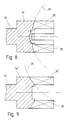
- the axial slots 35 in a technically very simple manner produced by a cutting or grinding wheel, which on free end of the coupling head 34 and is increasingly advanced axially.
- the disk circumference of the The grinding wheel is indicated at 36 in FIG. 8.
- Axial slots 35 require two operations, with two diametrical for each operation opposite axial slots 35 are made.
- the slot base of the axial slots 35 is in the form of a circular arc.
- a clutch disc 37 (Fig. 1, 2, 4 and 6) with four radial on the disc circumference protruding, in one piece with the clutch disc 37
- Coupling webs 371 - 374 which have the same circumferential angle are offset from each other by 90 °.
- Fig. 2 there are two diametrical Coupling webs 371 and 373 in the circumferential direction without play in the associated axial slots 35, while the two other coupling webs 372 and 374 with that for the tolerances occurring in the center offset between drive and distributor shaft 13,19 required play are, with axial slots 35 of the same width, so narrower are designed as the coupling webs 371.373.
- the clutch disc 37 carries a central recess 38, which receives a front pin 39 in a form-fitting manner, which on the Front side of the distributor shaft 19 projects coaxially (FIG. 1 and 2).
- the recess 38 is rectangular dimensioned, the two parallel long sides 381,382 at right angles to those coupling webs 371.373 run in their associated axial slots 35 lay in without play.
- On these long sides 381, 382 is the Front pin 39 of the distributor shaft 19 with parallel, pin surfaces 391, 392 pointing away from one another without play.
- the clutch disc 37 has the function of non-rotatable connection of drive shaft 13 and Distribution shaft 19 still the function of a Torque limitation.
- the clutch disc 37 is so trained that when a predetermined is exceeded Torque maximums the radially projecting coupling webs Cancel 371 - 374. So that a piston eater leads in the Distributor shaft 19 to break the clutch disc 37 and thus for decoupling the drive shaft and distributor shaft 13.19, so that further destruction in the Fuel injection pump can be prevented.
- the roller shoes 23 After inserting the clutch disc 37 into the clutch head 34, the roller shoes 23 are rotatably mounted therein Rollers 24 inserted into the axial slots 35.
- the Limit clutch webs 371 - 374 of clutch disc 37 thus the leadership of the roller shoes 23 in the axial slots 35 in the axial direction.
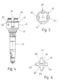
- On the axially opposite Page is the leadership of the roller shoes 23 by one Thrust washer 40 (Fig. 1.4 and 5) limited to the Coupling head 34 is placed.
- the coupling head 34 has at its free end with an axial section 341 reduced diameter.
- the thrust washer 40 On this axial section 341 is the thrust washer 40, which is attached to a Transition to reduced-diameter axial section 341 itself forming ring shoulder 342 of the coupling head 34 and offset with four by 90 ° circumferential angle to each other Tabs 401 engages in the axial slots 35.
- the rags 401 limit the thrust washer 40 together with the Clutch webs 371 - 374 of the clutch disc 37 die Axial movement of the roller shoes 23 in the Axial slots 35 formed guide slots Roller shoes 23.
- a Ball bearing 41 with inner bearing ring 42 and outer Bearing ring 43 and rolling balls 44 therebetween intended.
- the inner bearing ring 42 is in the Reduced axial section 341 radially against the Thrust washer 40 pressed on and with a locking ring 45, which engages in an annular groove 46 in the axial section 341, secured.
- the outer bearing ring 43 of the ball bearing 41 is added with play adjustment in the pump housing 10 and axially with the distributor body 11 against a housing shoulder 101 braced.
- the outer bearing ring 43 covers it together with the distributor body 11 an axial Installation recess 47 inside the pump housing 10. This Mounting recess 47 is for mounting the one-piece Cam ring 26 required with a radial protruding driver pin 48 on the injection adjuster 33 is coupled.
- the formation of the coupling head 34 on the drive shaft 13 for coupling the distributor shaft 19 is not on the Training of an even number of Axial slots 35, four in the present example, limited. So with an odd number of Radial bores 20 and radial pistons 21 lying therein in the distributor shaft 19 also an odd number of Axial slots 35 are provided in the coupling head 34 ', again each axial slot 35 'that of the radial piston 21 associated follower shoe 23 with rotatably mounted therein Roll 24 receives slidably in the radial direction.
- FIG. 7 is a cross section of such a coupling head 34 ' three axial slots 35 'shown, in turn a clutch disc 37 'with three Coupling webs 371 ', 372' and 373 'protrude.
- Corresponding the arrangement of the axial slots 35 ' has the coupling web 372 'from the coupling web 371' and the coupling web 373 ' a larger distance measured in circumferential angle than that two coupling webs 371 'and 373' from each other.
- the Coupling webs 371 'and 372' have in contrast to that Coupling web 373 'a crowned widening 50, with which in the circumferential direction without play in the assigned Insert axial slot 35 '.
- the coupling web has 373 ' however, circumferentially game within the associated axial slot 35 '.
- rectangular recess 38 is like this aligned that their two long sides 381 and 382 perpendicular to the middle coupling web 372 ' extend that of the other two coupling webs 371 ' and 373 'has the greatest distance.
- This constructive Design for an odd number of Axial slots 35 'in the coupling head 34' also provide one Cardanic articulation of the distributor shaft 19 on the Drive shaft 13 safely.
- the technically simple Making the odd number of axial slots 35 'in the hollow cylindrical coupling head 34 'is in FIG. 9 outlined.
- Each axial slot 35 ' is made individually axial positioning of a cutting or grinding wheel on the free End of the coupling head 34 'in the hollow cylinder wall incised.
- the disc circumference of the cutting disc is in Fig. 9 indicated by dash-dotted lines and designated 36.
Landscapes
- Engineering & Computer Science (AREA)
- General Engineering & Computer Science (AREA)
- Mechanical Engineering (AREA)
- Chemical & Material Sciences (AREA)
- Combustion & Propulsion (AREA)
- Fuel-Injection Apparatus (AREA)
Description
Beispielsweise können diese mit einer rotierenden Trenn- oder Schleifscheibe in die Zylinderwand des Kupplungskopfes von dessen freien Stirnseite her eingeschnitten werden, wobei die Schleifscheibe vom freien Ende des
Kupplungskopfes aus zunehmend axial vorgeschoben wird. Dabei können die Axialschnitte jeweils einzeln eingeschnitten werden. Bei geradzahligen Axialschlitzen im Kupplungskopf können aber auch jeweils zwei diametrai gegenüberliegenden Axialschlitze in einem einzigen arbeitsvorgang gleichzeitig eingeschnitten werden.
- Fig. 1
- einen Längsschnitt einer Kraftstoffeinspritzpumpe der Verteilerbauart mit Radialkolben für eine Brennkraftmaschine,
- Fig. 2
- einen Schnitt von Kupplungskopf und Nockenring gemäß Linie II-II in Fig. 1,
- Fig. 3
- einen Schnitt gemäß Linie III-III in Fig. 1,
- Fig. 4
- eine Seitenansicht einer Antriebswelle der Kraftstoffeinspritzpumpe in Fig. 1,
- Fig. 5
- eine Draufsicht einer auf dem Kupplungskopf der Antriebswelle in Fig. 4 sitzenden Anlaufscheibe,
- Fig. 6
- eine Draufsicht einer in dem Kupplungskopf der Antriebswelle in Fig. 4 einliegenden Kupplungsscheibe,
- Fig. 7
- einen Querschnitt des Kupplungskopfes der Antriebswelle in Fig. 4 mit darin einliegender Kupplungsscheibe gemäß einem weiteren Ausführungsbeispiel.
- Fig. 8 und 9
- jeweils einen Längsschnitt des Kupplungskopfes der Antriebswelle in Fig. 4 zur Verdeutlichung der Herstellung der Axialschlitze, schematisch skizziert.
Claims (12)
- Kraftstoffeinspritzpumpe der Verteilerbauart zur Versorgung einer Mehrzahl von Einspritzdüsen (29) von Brennkraftmaschinen, mit einer in einem Pumpengehäuse (10) gelagerten, rotierenden Antriebswelle (13), mit einer mit der Antriebswelle (13) drehfest gekuppelten Verteilerwelle (19), die bei Drehung sukzessive eine Verbindung zwischen einem in ihr integrierten Pumpenarbeitsraum (22) und einer der Einspritzdüsen (29) herstellt, mit in jeweils einer Radialbohrung (20) der Verteilerwelle (19) axial verschieblich einliegenden Pumpenkolben (21), die mit ihrer einen Stirnseite den Pumpenarbeitsraum (22) begrenzen und mit ihrer anderen Stirnseite über in Rollenschuhen (23) drehbeweglich gehaltenen Rollen (24) an einer Nockenbahn (25) eines zur Verteilerwelle (19) koaxialen, im Pumpengehäuse (10) festgelegten Nockenrings (26) kraftschlüssig anliegen, und an dem der Verteilerwelle (19) zugekehrten Ende der Antriebswelle (13) ein die Verteilerwelle (19) becherartig übergreifender, stutzenförmiger Kupplungskopf (34) ausgebildet ist, daß in der Hohlzylinderwand des Kupplungskopfes (34) eine der Zahl der Radialbohrungen (20) in der Verteilerwelle (19) entsprechende Zahl von am freien Stirnende des Kupplungskopfes (34) frei auslaufenden Axialschlitzen (35) so eingebracht ist, daß die Axialschlitze (35) mit den Radialbohrungen (20) in der Verteilerwelle (11) radial fluchten, und daß die Rollenschuhe (23) mit Rollen (24) in den Axialschlitzen (35) radial verschieblich einliegen und die drehfeste Kupplung zwischen Antriebs- und Verteilerwelle (13, 19) durch eine Kupplungsscheibe (37; 37') erfolgt, die mit am Scheibenumfang radial vorspringenden, vorzugsweise mit der Kupplungsscheibe (37; 37') einstückigen Kupplungsstegen (371-374; 371'-373') in den Axialschlitzen (35; 35') im Kupplungskopf (34; 34') einliegt, dadurch gekennzeichnet, daß die Kupplungsscheibe eine zentrale Ausnehmung (38) aufweist mit zwei zueinander parallel verlaufenden Flanken (381, 382), die einen an der Stirnseite der Verteilerwelle (19) vorstehenden mit zwei zueinander parallelen Zapfenflächen (391, 392) versehenen Zapfen (39) formschlüssig aufnimmt.
- Einspritzpumpe nach Anspruch 1, dadurch gekennzeichnet, daß der Formschluß zwischen den radialen Kupplungsstegen (371-374;371'-373') der Kupplungsscheibe (37;37') und den Axialschlitzen (35;35') im Kupplungskopf (34;34') einerseits und zwischen der zentralen Ausnehmung (38) in der Kupplungsscheibe (37;37') und dem Stirnzapfen (39) an der Verteilerwelle (19) andererseits so getroffen ist, daß eine kardanischer Anlenkung von Antriebswelle (11) und Verteilerwelle (19) besteht.
- Einspritzpumpe nach Anspruch 2, dadurch gekennzeichnet, daß insgesamt vier um jeweils 90° zueinander versetzt angeordnete Axialschlitze (35) im Kupplungskopf (34) angeordnet sind, daß die Kupplungsscheibe (37) vier um 90° zueinander versetzt angeordnete radiale Kupplungsstege (371,374) aufweist, von denen zwei diametral zueinander angeordnete Kupplungsstege (371-373) spiellos in den Axialschlitzen (35) einliegen, und daß die Ausnehmung (38) in der Kupplungsscheibe (37) zwei parallel und rechtwinklig zu den spiellos in den Axialschlitzen (35) einliegenden Kupplungsstege (371,373) verlaufende Flanken (381,383) aufweist, an denen der Stirnzapfen (39) der Verteilerwelle (19) mit voneinander und wegweisenden parallelen Zapfenflächen (391,392) anliegt.
- Einspritzpumpe nach Anspruch 3, dadurch gekennzeichnet, daß die zwei verbleibenden einander diametral gegenüberliegenden Kupplungsstege (372,374) der Kupplungsscheibe (37) mit Spiel in Umfangsrichtung in den zugeordneten Axialschlitzen (35) im Kupplungskopf (34) einliegen.
- Einspritzpumpe nach Anspruch 2, dadurch gekennzeichnet, daß insgesamt drei Axialschlitze (35') im Kupplungskopf (34') der Verteilerwelle (19) und entsprechend drei Kupplungsstege (371'-373') an der Kupplungsscheibe (37') vorgesehen sind, von denen die um den größeren Umfangswinkel zueinander versetzten Kupplungsstege (371',372') durch eine ballige Verbreiterung (50) ihre Stegbreite in Umfangsrichtung spiellos in den zugeordneten Axialschlitzen (35') einliegen, und daß die Ausnehmung (38) in der Kupplungsscheibe (37') zwei parallel und rechtwinklig zu dem am weitesten von den beiden anderen Kupplungsstegen (371',373') entfernt liegenden Kupplungsteg (372') sich erstreckende Flanken (381,382) aufweist, an denen der Stirnzapfen (39) der Verteilerwelle (19) mit voneinander wegweisenden parallelen Zapfenflächen (391,392) spiellos anliegt.
- Einspritzpumpe nach einem der Ansprüche 1 - 5, dadurch gekennzeichnet, daß die Kupplungsscheibe (37) am Schlitzgrund der Axialschlitze (35) aufliegt und daß die Rollenschuhe (23) axial an der Kupplungsscheibe (37) anliegen.
- Einspritzpumpe nach einem der Ansprüche 1 - 5, dadurch gekennzeichnet, daß die Kupplungsscheibe (37) zur Übertragung eines maximalen Drehmoments derart ausgebildet ist, daß bei Überschreiten des Drehmomentmaximums die radial vorstehenden Kupplungsstege (371-374) abbrechen.
- Einspritzpumpe nach einem der Ansprüche 1 - 7, dadurch gekennzeichnet, daß die Axialschlitze (35;35') mittels einer rotierenden Schleifscheibe in die Zylinderwand des Kupplungskopfes (34;34') eingeschnitten werden, indem die Schleifscheibe vom freien Ende des Kupplungskopfes (34;34') her axial vorgeschoben wird.
- Einspritzpumpe nach einem der Ansprüche 1 - 8, dadurch gekennzeichnet, daß die Lagerung der Antriebswelle (13) im Pumpengehäuse (10) durch eine Gleitlagerbuchse (14) nahe dem Austritt der Antriebswelle (13) aus dem Pumpengehäuse (10) und durch ein Kugellager (41) zwischen Kupplungskopf (34) und Pumpengehäuse (10) vorgenommen ist, das sich radial und axial am Kupplungskopf (34) abstützt.
- Einspritzpumpe nach Anspruch 9, dadurch gekennzeichnet, daß der Kupplungskopf (34) an seinem freien Stirnende einen Axialabschnitt (341) mit reduziertem Durchmesser aufweist, daß an der am Übergang zum durchmesserreduzierten Axialabschnitt sich ausbildenden Ringschulter (342) eine Anlaufscheibe (40) anliegt und daß der innere Lagerring (42) des Kugellagers (41) an dem durchmesserreduzierten Axialabschnitt (341) des Kupplungskopfes (34) und axial an der Anlaufscheibe (40) anliegt.
- Einspritzpumpe nach Anspruch 9 oder 10, dadurch gekennzeichnet, daß der innere Lagerring (42) des Kugellagers (41) gegen die Anlaufscheibe (40) auf den durchmesserreduzierten Axialabschnitt (341) des Kupplungskopfes (34) aufgepreßt und mit einem in einer Ringnut (46) im Axialabschnitt (341) eingesetzten Sicherungsring (45) gesichert ist.
- Einspritzpumpe nach einem der Ansprüche 9 - 10, dadurch gekennzeichnet, daß der äußere Lagerring (43) des Kugellagers (41) sich in Axialrichtung an einer Gehäuseschulter (101) im Pumpengehäuse (10) abstützt und durch einen in das Pumpengehäuse (10) stirnseitig eingesetzten, die Verteilerwelle (19) aufnehmenden Verteilerkörper (11) an der Gehäuseschulter (101) festgespannt ist.
Applications Claiming Priority (3)
| Application Number | Priority Date | Filing Date | Title |
|---|---|---|---|
| DE4341424 | 1993-12-04 | ||
| DE4341424A DE4341424A1 (de) | 1993-12-04 | 1993-12-04 | Kraftstoffeinspritzpumpe |
| PCT/DE1994/001390 WO1995015434A1 (de) | 1993-12-04 | 1994-11-24 | Kraftstoffeinspritzpumpe |
Publications (2)
| Publication Number | Publication Date |
|---|---|
| EP0682746A1 EP0682746A1 (de) | 1995-11-22 |
| EP0682746B1 true EP0682746B1 (de) | 1998-08-05 |
Family
ID=6504219
Family Applications (1)
| Application Number | Title | Priority Date | Filing Date |
|---|---|---|---|
| EP95900660A Expired - Lifetime EP0682746B1 (de) | 1993-12-04 | 1994-11-24 | Kraftstoffeinspritzpumpe |
Country Status (8)
| Country | Link |
|---|---|
| US (1) | US5685274A (de) |
| EP (1) | EP0682746B1 (de) |
| JP (1) | JP3647452B2 (de) |
| KR (1) | KR100377896B1 (de) |
| CN (1) | CN1053261C (de) |
| DE (2) | DE4341424A1 (de) |
| ES (1) | ES2120162T3 (de) |
| WO (1) | WO1995015434A1 (de) |
Families Citing this family (11)
| Publication number | Priority date | Publication date | Assignee | Title |
|---|---|---|---|---|
| GB9701263D0 (en) | 1997-01-22 | 1997-03-12 | Lucas Ind Plc | Drive arrangement |
| IL133708A0 (en) | 1997-06-30 | 2001-04-30 | Rhone Poulence Rorer S A | Improved method for transferring nucleic acid into multicelled eukaryotic organism cells and combination thereof |
| DE69826124T3 (de) | 1997-06-30 | 2007-10-11 | Institut Gustave Roussy | Verabreichung der nukleinsäure in den quergestreiften muskel |
| US5952969A (en) * | 1997-08-18 | 1999-09-14 | Telefonakiebolaget L M Ericsson (Publ) | Method and system for determining the position of mobile radio terminals |
| JP4052220B2 (ja) | 2003-10-08 | 2008-02-27 | 株式会社デンソー | 燃料噴射ポンプ |
| DE102006037176A1 (de) * | 2006-08-09 | 2008-02-14 | Robert Bosch Gmbh | Kraftstoffeinspritzpumpe mit einer verbesserten Antriebskupplung |
| DE112009002590A5 (de) * | 2008-10-15 | 2011-07-28 | ixetic Hückeswagen GmbH, 42499 | Kupplung für eine Pumpe |
| RU2406893C2 (ru) * | 2009-01-11 | 2010-12-20 | Открытое акционерное общество "Уральское конструкторское бюро транспортного машиностроения" | Компенсирующая муфта |
| DE112011104267A5 (de) * | 2010-12-07 | 2013-10-10 | Ixetic Hückeswagen Gmbh | Kupplung, Rotor und Baugruppe für eine Pumpe |
| DE102010063321A1 (de) * | 2010-12-17 | 2012-06-21 | Robert Bosch Gmbh | Hochdruckpumpe |
| DE102016220854B4 (de) * | 2016-10-24 | 2018-07-05 | Schaeffler Technologies AG & Co. KG | Verstellvorrichtung |
Family Cites Families (16)
| Publication number | Priority date | Publication date | Assignee | Title |
|---|---|---|---|---|
| DE167747C (de) * | ||||
| FR1080880A (fr) * | 1953-06-09 | 1954-12-14 | American Bosch Corp | Appareil pour alimenter en combustible un moteur à combustion interne |
| DE1108512B (de) * | 1956-08-22 | 1961-06-08 | Bosch Gmbh Robert | Kraftstoffeinspritzpumpe fuer mehrzylindrige Brennkraftmaschinen |
| FR2337819A1 (fr) * | 1976-01-12 | 1977-08-05 | Sigma Diesel | Perfectionnements apportes aux pompes d'injection pour moteurs a combustion interne et procede pour le calage de telles pompes d'injection |
| FR2396169A1 (fr) * | 1977-06-28 | 1979-01-26 | Achard Paul | Perfectionnement apporte aux pompes d'injection, a distributeur rotatif, pour moteur diesel |
| GB2037365B (en) * | 1978-11-25 | 1982-12-08 | Lucas Industries Ltd | Liquid fuel injection pumping apparatus |
| GB2030640B (en) * | 1979-07-30 | 1982-09-15 | Lucas Industries Ltd | Fuel injection pumping apparatus |
| US4362141A (en) * | 1980-02-16 | 1982-12-07 | Lucas Industries Limited | Fuel injection pumping apparatus |
| GB2080572B (en) * | 1980-07-26 | 1984-03-14 | Lucas Industries Ltd | Governor for engines |
| US4462370A (en) * | 1980-12-31 | 1984-07-31 | Lucas Industries Limited | Fuel injection pumping apparatus |
| DE3437933A1 (de) * | 1984-10-17 | 1986-04-24 | Robert Bosch Gmbh, 7000 Stuttgart | Kraftstoffeinspritzvorrichtung fuer brennkraftmaschinen |
| DE3920459A1 (de) * | 1989-06-22 | 1991-01-03 | Bosch Gmbh Robert | Kraftstoffeinspritzpumpe fuer brennkraftmaschinen |
| GB9019098D0 (en) * | 1990-09-01 | 1990-10-17 | Lucas Ind Plc | Fuel pumping apparatus |
| DE4105353A1 (de) * | 1991-02-21 | 1992-08-27 | Bosch Gmbh Robert | Kraftstoffeinspritzpumpe fuer brennkraftmaschinen |
| WO1993013308A1 (en) * | 1991-12-20 | 1993-07-08 | Lucas Industries Public Limited Company | Fuel pumping apparatus |
| GB9420254D0 (en) * | 1994-10-07 | 1994-11-23 | Lucas Ind Plc | Fuel injection pump |
-
1993
- 1993-12-04 DE DE4341424A patent/DE4341424A1/de not_active Withdrawn
-
1994
- 1994-11-24 US US08/464,897 patent/US5685274A/en not_active Expired - Fee Related
- 1994-11-24 DE DE59406617T patent/DE59406617D1/de not_active Expired - Lifetime
- 1994-11-24 ES ES95900660T patent/ES2120162T3/es not_active Expired - Lifetime
- 1994-11-24 WO PCT/DE1994/001390 patent/WO1995015434A1/de not_active Ceased
- 1994-11-24 KR KR1019950703202A patent/KR100377896B1/ko not_active Expired - Fee Related
- 1994-11-24 CN CN94191097A patent/CN1053261C/zh not_active Expired - Fee Related
- 1994-11-24 EP EP95900660A patent/EP0682746B1/de not_active Expired - Lifetime
- 1994-11-24 JP JP51532995A patent/JP3647452B2/ja not_active Expired - Fee Related
Also Published As
| Publication number | Publication date |
|---|---|
| US5685274A (en) | 1997-11-11 |
| JPH08506875A (ja) | 1996-07-23 |
| CN1053261C (zh) | 2000-06-07 |
| KR100377896B1 (ko) | 2003-06-09 |
| WO1995015434A1 (de) | 1995-06-08 |
| CN1117306A (zh) | 1996-02-21 |
| ES2120162T3 (es) | 1998-10-16 |
| KR960701296A (ko) | 1996-02-24 |
| EP0682746A1 (de) | 1995-11-22 |
| DE59406617D1 (de) | 1998-09-10 |
| DE4341424A1 (de) | 1995-06-08 |
| JP3647452B2 (ja) | 2005-05-11 |
Similar Documents
| Publication | Publication Date | Title |
|---|---|---|
| DE4227853C2 (de) | Kraftstoffeinspritzpumpe für Brennkraftmaschinen | |
| DE3590194C2 (de) | Brennstoff-Einspritzpumpe | |
| DE10355027A1 (de) | Hochdruckpumpe, insbesondere für eine Kraftstoffeinspritzeinrichtung einer Brennkraftmaschine | |
| DE3840691A1 (de) | Radialkolbenpumpe | |
| DE4341424A1 (de) | Kraftstoffeinspritzpumpe | |
| DE3127395C2 (de) | Gegen Federkraft mit Druckmittel einrückbare Reibscheibenkupplung | |
| EP1714030A1 (de) | Hochdruckpumpe, insbesondere für eine kraftstoffeinspritzeinrichtung einer brennkraftmaschine | |
| EP2297447B1 (de) | Hochdruckpumpe | |
| CH678753A5 (de) | ||
| DE19537561A1 (de) | Werkzeughalter | |
| EP0461221B1 (de) | Kraftstoffeinsprizteinrichtung für einspritzbrennkraftmaschinen | |
| EP0461213B1 (de) | Kraftstoffeinspritzpumpe für brennkraftmaschinen | |
| DE3542938C2 (de) | ||
| DE3201011C2 (de) | ||
| DE4227854A1 (de) | Kraftstoffeinspritzpumpe für Brennkraftmaschinen | |
| DE3334016A1 (de) | Druckfluessigkeitseinrichtung, motor oder pumpe | |
| DE702173C (de) | Einspritzvorrichtung fuer mehrzylindrige Brennkraftmaschinen | |
| DE19701049C1 (de) | Radialwalzkopf | |
| DE3718535C2 (de) | ||
| WO1987005969A1 (fr) | Pompe d'injection de carburant pour moteurs a combustion interne | |
| DE19549223A1 (de) | Brennkraftmaschine | |
| EP0597250B1 (de) | Kraftstoffeinspritzpumpe | |
| DE3737042C2 (de) | ||
| EP0219510A1 (de) | Kraftstoffeinspritzpumpe | |
| EP0153919B1 (de) | Kraftstoffeinspritzpumpe für Brennkraftmaschinen |
Legal Events
| Date | Code | Title | Description |
|---|---|---|---|
| PUAI | Public reference made under article 153(3) epc to a published international application that has entered the european phase |
Free format text: ORIGINAL CODE: 0009012 |
|
| AK | Designated contracting states |
Kind code of ref document: A1 Designated state(s): DE ES FR GB IT |
|
| 17P | Request for examination filed |
Effective date: 19951208 |
|
| 17Q | First examination report despatched |
Effective date: 19970422 |
|
| GRAG | Despatch of communication of intention to grant |
Free format text: ORIGINAL CODE: EPIDOS AGRA |
|
| GRAG | Despatch of communication of intention to grant |
Free format text: ORIGINAL CODE: EPIDOS AGRA |
|
| GRAH | Despatch of communication of intention to grant a patent |
Free format text: ORIGINAL CODE: EPIDOS IGRA |
|
| GRAH | Despatch of communication of intention to grant a patent |
Free format text: ORIGINAL CODE: EPIDOS IGRA |
|
| GRAA | (expected) grant |
Free format text: ORIGINAL CODE: 0009210 |
|
| AK | Designated contracting states |
Kind code of ref document: B1 Designated state(s): DE ES FR GB IT |
|
| REF | Corresponds to: |
Ref document number: 59406617 Country of ref document: DE Date of ref document: 19980910 |
|
| ET | Fr: translation filed | ||
| REG | Reference to a national code |
Ref country code: ES Ref legal event code: FG2A Ref document number: 2120162 Country of ref document: ES Kind code of ref document: T3 |
|
| GBT | Gb: translation of ep patent filed (gb section 77(6)(a)/1977) |
Effective date: 19981007 |
|
| PLBE | No opposition filed within time limit |
Free format text: ORIGINAL CODE: 0009261 |
|
| STAA | Information on the status of an ep patent application or granted ep patent |
Free format text: STATUS: NO OPPOSITION FILED WITHIN TIME LIMIT |
|
| 26N | No opposition filed | ||
| REG | Reference to a national code |
Ref country code: GB Ref legal event code: IF02 |
|
| PGFP | Annual fee paid to national office [announced via postgrant information from national office to epo] |
Ref country code: ES Payment date: 20071127 Year of fee payment: 14 |
|
| PGFP | Annual fee paid to national office [announced via postgrant information from national office to epo] |
Ref country code: IT Payment date: 20071127 Year of fee payment: 14 |
|
| PGFP | Annual fee paid to national office [announced via postgrant information from national office to epo] |
Ref country code: GB Payment date: 20071123 Year of fee payment: 14 Ref country code: FR Payment date: 20071120 Year of fee payment: 14 |
|
| GBPC | Gb: european patent ceased through non-payment of renewal fee |
Effective date: 20081124 |
|
| PG25 | Lapsed in a contracting state [announced via postgrant information from national office to epo] |
Ref country code: IT Free format text: LAPSE BECAUSE OF NON-PAYMENT OF DUE FEES Effective date: 20081124 |
|
| REG | Reference to a national code |
Ref country code: FR Ref legal event code: ST Effective date: 20090731 |
|
| PG25 | Lapsed in a contracting state [announced via postgrant information from national office to epo] |
Ref country code: GB Free format text: LAPSE BECAUSE OF NON-PAYMENT OF DUE FEES Effective date: 20081124 |
|
| REG | Reference to a national code |
Ref country code: ES Ref legal event code: FD2A Effective date: 20081125 |
|
| PG25 | Lapsed in a contracting state [announced via postgrant information from national office to epo] |
Ref country code: ES Free format text: LAPSE BECAUSE OF NON-PAYMENT OF DUE FEES Effective date: 20081125 |
|
| PGFP | Annual fee paid to national office [announced via postgrant information from national office to epo] |
Ref country code: DE Payment date: 20100121 Year of fee payment: 16 |
|
| REG | Reference to a national code |
Ref country code: DE Ref legal event code: R119 Ref document number: 59406617 Country of ref document: DE Effective date: 20110601 Ref country code: DE Ref legal event code: R119 Ref document number: 59406617 Country of ref document: DE Effective date: 20110531 |
|
| PG25 | Lapsed in a contracting state [announced via postgrant information from national office to epo] |
Ref country code: FR Free format text: LAPSE BECAUSE OF NON-PAYMENT OF DUE FEES Effective date: 20081130 Ref country code: DE Free format text: LAPSE BECAUSE OF NON-PAYMENT OF DUE FEES Effective date: 20110531 |