EP0682421B1 - Verfahren und Vorrichtung zum Aufzeichnen eines digitalen Audiosignals bestehend aus einer Vielzahl von Audiokanälen und Verfahren und Vorrichtung zum Wiedergeben derselben - Google Patents
Verfahren und Vorrichtung zum Aufzeichnen eines digitalen Audiosignals bestehend aus einer Vielzahl von Audiokanälen und Verfahren und Vorrichtung zum Wiedergeben derselben Download PDFInfo
- Publication number
- EP0682421B1 EP0682421B1 EP95303190A EP95303190A EP0682421B1 EP 0682421 B1 EP0682421 B1 EP 0682421B1 EP 95303190 A EP95303190 A EP 95303190A EP 95303190 A EP95303190 A EP 95303190A EP 0682421 B1 EP0682421 B1 EP 0682421B1
- Authority
- EP
- European Patent Office
- Prior art keywords
- audio
- data
- recorded
- channels
- channel
- Prior art date
- Legal status (The legal status is an assumption and is not a legal conclusion. Google has not performed a legal analysis and makes no representation as to the accuracy of the status listed.)
- Expired - Lifetime
Links
Images


Classifications
-
- H—ELECTRICITY
- H04—ELECTRIC COMMUNICATION TECHNIQUE
- H04N—PICTORIAL COMMUNICATION, e.g. TELEVISION
- H04N9/00—Details of colour television systems
- H04N9/79—Processing of colour television signals in connection with recording
- H04N9/80—Transformation of the television signal for recording, e.g. modulation, frequency changing; Inverse transformation for playback
- H04N9/82—Transformation of the television signal for recording, e.g. modulation, frequency changing; Inverse transformation for playback the individual colour picture signal components being recorded simultaneously only
- H04N9/8205—Transformation of the television signal for recording, e.g. modulation, frequency changing; Inverse transformation for playback the individual colour picture signal components being recorded simultaneously only involving the multiplexing of an additional signal and the colour video signal
- H04N9/8233—Transformation of the television signal for recording, e.g. modulation, frequency changing; Inverse transformation for playback the individual colour picture signal components being recorded simultaneously only involving the multiplexing of an additional signal and the colour video signal the additional signal being a character code signal
-
- G—PHYSICS
- G11—INFORMATION STORAGE
- G11B—INFORMATION STORAGE BASED ON RELATIVE MOVEMENT BETWEEN RECORD CARRIER AND TRANSDUCER
- G11B5/00—Recording by magnetisation or demagnetisation of a record carrier; Reproducing by magnetic means; Record carriers therefor
- G11B5/02—Recording, reproducing, or erasing methods; Read, write or erase circuits therefor
- G11B5/09—Digital recording
-
- G—PHYSICS
- G11—INFORMATION STORAGE
- G11B—INFORMATION STORAGE BASED ON RELATIVE MOVEMENT BETWEEN RECORD CARRIER AND TRANSDUCER
- G11B20/00—Signal processing not specific to the method of recording or reproducing; Circuits therefor
- G11B20/10—Digital recording or reproducing
- G11B20/10527—Audio or video recording; Data buffering arrangements
-
- G—PHYSICS
- G11—INFORMATION STORAGE
- G11B—INFORMATION STORAGE BASED ON RELATIVE MOVEMENT BETWEEN RECORD CARRIER AND TRANSDUCER
- G11B27/00—Editing; Indexing; Addressing; Timing or synchronising; Monitoring; Measuring tape travel
- G11B27/02—Editing, e.g. varying the order of information signals recorded on, or reproduced from, record carriers
- G11B27/031—Electronic editing of digitised analogue information signals, e.g. audio or video signals
- G11B27/032—Electronic editing of digitised analogue information signals, e.g. audio or video signals on tapes
-
- G—PHYSICS
- G11—INFORMATION STORAGE
- G11B—INFORMATION STORAGE BASED ON RELATIVE MOVEMENT BETWEEN RECORD CARRIER AND TRANSDUCER
- G11B27/00—Editing; Indexing; Addressing; Timing or synchronising; Monitoring; Measuring tape travel
- G11B27/10—Indexing; Addressing; Timing or synchronising; Measuring tape travel
- G11B27/11—Indexing; Addressing; Timing or synchronising; Measuring tape travel by using information not detectable on the record carrier
-
- G—PHYSICS
- G11—INFORMATION STORAGE
- G11B—INFORMATION STORAGE BASED ON RELATIVE MOVEMENT BETWEEN RECORD CARRIER AND TRANSDUCER
- G11B27/00—Editing; Indexing; Addressing; Timing or synchronising; Monitoring; Measuring tape travel
- G11B27/10—Indexing; Addressing; Timing or synchronising; Measuring tape travel
- G11B27/19—Indexing; Addressing; Timing or synchronising; Measuring tape travel by using information detectable on the record carrier
- G11B27/28—Indexing; Addressing; Timing or synchronising; Measuring tape travel by using information detectable on the record carrier by using information signals recorded by the same method as the main recording
- G11B27/30—Indexing; Addressing; Timing or synchronising; Measuring tape travel by using information detectable on the record carrier by using information signals recorded by the same method as the main recording on the same track as the main recording
- G11B27/3027—Indexing; Addressing; Timing or synchronising; Measuring tape travel by using information detectable on the record carrier by using information signals recorded by the same method as the main recording on the same track as the main recording used signal is digitally coded
- G11B27/3063—Subcodes
-
- H—ELECTRICITY
- H04—ELECTRIC COMMUNICATION TECHNIQUE
- H04H—BROADCAST COMMUNICATION
- H04H20/00—Arrangements for broadcast or for distribution combined with broadcast
- H04H20/28—Arrangements for simultaneous broadcast of plural pieces of information
-
- H—ELECTRICITY
- H04—ELECTRIC COMMUNICATION TECHNIQUE
- H04H—BROADCAST COMMUNICATION
- H04H20/00—Arrangements for broadcast or for distribution combined with broadcast
- H04H20/86—Arrangements characterised by the broadcast information itself
-
- H—ELECTRICITY
- H04—ELECTRIC COMMUNICATION TECHNIQUE
- H04N—PICTORIAL COMMUNICATION, e.g. TELEVISION
- H04N9/00—Details of colour television systems
- H04N9/79—Processing of colour television signals in connection with recording
- H04N9/80—Transformation of the television signal for recording, e.g. modulation, frequency changing; Inverse transformation for playback
- H04N9/804—Transformation of the television signal for recording, e.g. modulation, frequency changing; Inverse transformation for playback involving pulse code modulation of the colour picture signal components
- H04N9/8042—Transformation of the television signal for recording, e.g. modulation, frequency changing; Inverse transformation for playback involving pulse code modulation of the colour picture signal components involving data reduction
- H04N9/8047—Transformation of the television signal for recording, e.g. modulation, frequency changing; Inverse transformation for playback involving pulse code modulation of the colour picture signal components involving data reduction using transform coding
-
- H—ELECTRICITY
- H04—ELECTRIC COMMUNICATION TECHNIQUE
- H04N—PICTORIAL COMMUNICATION, e.g. TELEVISION
- H04N9/00—Details of colour television systems
- H04N9/79—Processing of colour television signals in connection with recording
- H04N9/80—Transformation of the television signal for recording, e.g. modulation, frequency changing; Inverse transformation for playback
- H04N9/804—Transformation of the television signal for recording, e.g. modulation, frequency changing; Inverse transformation for playback involving pulse code modulation of the colour picture signal components
- H04N9/806—Transformation of the television signal for recording, e.g. modulation, frequency changing; Inverse transformation for playback involving pulse code modulation of the colour picture signal components with processing of the sound signal
- H04N9/8063—Transformation of the television signal for recording, e.g. modulation, frequency changing; Inverse transformation for playback involving pulse code modulation of the colour picture signal components with processing of the sound signal using time division multiplex of the PCM audio and PCM video signals
-
- G—PHYSICS
- G11—INFORMATION STORAGE
- G11B—INFORMATION STORAGE BASED ON RELATIVE MOVEMENT BETWEEN RECORD CARRIER AND TRANSDUCER
- G11B20/00—Signal processing not specific to the method of recording or reproducing; Circuits therefor
- G11B20/10—Digital recording or reproducing
- G11B20/10527—Audio or video recording; Data buffering arrangements
- G11B2020/10537—Audio or video recording
- G11B2020/10592—Audio or video recording specifically adapted for recording or reproducing multichannel signals
-
- G—PHYSICS
- G11—INFORMATION STORAGE
- G11B—INFORMATION STORAGE BASED ON RELATIVE MOVEMENT BETWEEN RECORD CARRIER AND TRANSDUCER
- G11B2220/00—Record carriers by type
- G11B2220/60—Solid state media
- G11B2220/65—Solid state media wherein solid state memory is used for storing indexing information or metadata
- G11B2220/652—Solid state media wherein solid state memory is used for storing indexing information or metadata said memory being attached to the recording medium
- G11B2220/655—Memory in cassette [MIC]
-
- G—PHYSICS
- G11—INFORMATION STORAGE
- G11B—INFORMATION STORAGE BASED ON RELATIVE MOVEMENT BETWEEN RECORD CARRIER AND TRANSDUCER
- G11B2220/00—Record carriers by type
- G11B2220/90—Tape-like record carriers
-
- H—ELECTRICITY
- H04—ELECTRIC COMMUNICATION TECHNIQUE
- H04N—PICTORIAL COMMUNICATION, e.g. TELEVISION
- H04N5/00—Details of television systems
- H04N5/76—Television signal recording
- H04N5/78—Television signal recording using magnetic recording
- H04N5/782—Television signal recording using magnetic recording on tape
- H04N5/7824—Television signal recording using magnetic recording on tape with rotating magnetic heads
- H04N5/7826—Television signal recording using magnetic recording on tape with rotating magnetic heads involving helical scanning of the magnetic tape
- H04N5/78263—Television signal recording using magnetic recording on tape with rotating magnetic heads involving helical scanning of the magnetic tape for recording on tracks inclined relative to the direction of movement of the tape
- H04N5/78266—Television signal recording using magnetic recording on tape with rotating magnetic heads involving helical scanning of the magnetic tape for recording on tracks inclined relative to the direction of movement of the tape using more than one track for the recording of one television field or frame, i.e. segmented recording
Definitions
- This invention relates to the recording and reproduction of data. More particularly, but not exclusively, the invention relates to digital video and audio signal recording and reproducing apparatus, and, in particular, to control data associated with digital audio signals.
- a bilingual broadcast is a program in which the main language is Japanese and the sub language is English.
- Another example of a bilingual broadcast is a sports program in which the main "language” is a commentary and the sub "language” is a commentary about a team.
- "multilingual" encompasses both of the aforementioned examples, namely, audio signals with the same content in different languages and audio signals with different contents in the same language.
- DE 38 43 821 A1 In a commercial digital video cassette recorder (VCR) format that has been previously proposed in German patent application serial no. DE 38 43 821 A1, recording and reproducing formats of digital audio signals have been defined for both High Definition (HD) Video and Standard Definition (SD) video.
- DE 38 43 821 A1 also discloses a recording apparatus which records packs of data in tracks with video signals on a recording medium. The packs of data are recorded in separate areas of the tracks interposed between areas of recorded video signals.
- SD signals For SD signals, a two-channel mode (SD 2 ch) and a four-channel mode (SD 4 ch) have been defined.
- SD 4 ch For HD signals, a four-channel mode (HD 4 ch) and an eight-channel mode (HD 8 ch) have been defined. These four modes are considered in two groups. The amount of data used to represent a SD or HD signal in the first of the modes is twice the amount of data used to represent the signal in the second of the modes.
- the first group in which 16-bit linear quantizing is performed at sampling frequencies of 48 kHz, 44.1 kHz, and 32 kHz, includes the two-channel mode of SD and the four-channel mode of HD, shown in Figs. 1A and 1C, respectively.
- the second group in which 12-bit non-linear quantizing is performed at a sampling frequency of 32 kHz, includes the four-channel mode of SD and the eight-channel mode of HD, shown in Figs. 1B and 1D, respectively.
- Ten tracks are used to represent one SD video frame according to the NTSC standard (525 lines/60 Hz). Twelve tracks are used to represent one SD video frame according to the PAL standard (525 lines/50 Hz). In ten tracks (60 Hz SD system) or twelve tracks (50 Hz SD system), there is also capacity for two channels of digital audio signals each in 16-bit mode or four channels in 12-bit mode.
- Twenty tracks (1125 lines/60 Hz) or twenty four tracks (1250 lines/50 Hz) are used to represent one HD video frame.
- audio signals for four channels can be recorded, and, in the 12-bit mode, audio signals for eight channels can be recorded.
- a control data area AAUX for recording control data associated with the digital audio data is provided in each track.
- a mode signal referred to as AUDIO MODE is recorded in the AAUX area.
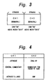
- Fig. 2 is a table indicating the meaning of the values of the AUDIO MODE data, using the following abbreviations:
- Fig. 4 At least three possibilities exist when the AUDIO MODE is recorded as shown in Fig. 3.
- the first possibility is that Japanese language is recorded on channel 1 and English language is recorded on channel 2.
- the second possibility is that general commentary is recorded on channel 1 and the specific commentary, such as for a team, is recorded on channel 2.
- the third possibility is that acting dialogue is recorded on channel 1 and background music is recorded on channel 2.
- a VCR that can record audio signals on eight channels, such as a HDVCR, can record a four-language stereo broadcasting program simultaneously with the above-mentioned Euro Sports channel.
- a HDVCR can record a four-language stereo broadcasting program simultaneously with the above-mentioned Euro Sports channel.
- such a recording format cannot be distinguished.
- European patent application EP-A-0 381 807 discloses a method for recording information in which a separate identification code is provided to identify each of a plurality of multilingual audio channels. It is also known from German patent application No. DE 32 38 399 to arrange a video recorder to detect and record stereo audio signals as well as non-correlated monophonic sound signals such as those used for programmes in two languages. Similarly German patent application no. DE 36 42 411 discloses a television receiver for detecting and recovering stereo, mono or two mono audio signals corresponding to a transmission in two languages.
- a digital audio signal including a plurality of audio channels is received by a recording apparatus.
- a multilingual indication is generated when at least two of the audio channels are associated with a common program, and the multilingual indication is combined with the digital audio signal.
- a digital audio signal including a plurality of audio channels and a multilingual indication indicating whether at least two of the audio channels are associated with a common program is received.
- a display is activated when the multilingual indication indicates that at least two of the audio channels are associated with a common program.
- a preferred embodiment of the invention disclosed hereinbelow provides:
- a recorded multilingual program can be recognized without need to reproduce all channels thereof.
- a main audio signal can be automatically reproduced without need to select a channel.
- one of the languages can be selected by the user.
- the present invention is applied to a digital VCR that compresses digital video signals and records and reproduces the signals to and from a tape.
- the present invention can be applied to a recording and reproducing apparatus that uses another recording medium such as an optical disc.
- the present invention can also be applied to a system that transmits digital audio signals through a communication line.
- composite digital color video data is separated into a luminance signal Y and color difference signals (R - Y) and (B - Y).
- the separated signals are compressed using, for example, an orthogonal transformation such as a discrete cosine transformation (DCT) and variable length encoding.
- the compressed signals are recorded on a magnetic tape by a rotating head in a SD system (525 lines/60 Hz or 652 lines/50 Hz) or a HD system (1125 lines/60 Hz or 1250 lines/50 Hz).
- a data management system including an application ID.
- a cassette has Video Auxiliary Data (VAUX), Audio Auxiliary Data (AAUX), sub-code data, and a memory in the cassette (MIC).
- VAUX Video Auxiliary Data
- AAUX Audio Auxiliary Data
- MIC memory in the cassette
- the cassette, mechanism, servo system, ITI area generating/detecting circuit, and so forth of a home-use digital VCR can be used in a completely different product such as a data streamer or a multiple-track digital tape recorder.
- the content of one area that has been predetermined can be defined corresponding to the application ID thereof.
- a variety of data such as video data, video data + audio data, and computer data can be designated.
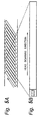
- Fig. 5A shows tracks formed obliquely on a tape for use with a digital VCR embodying the present invention.
- Fig. 5B shows one of the tracks illustrated in Fig. 5A.
- a timing block is formed so as to securely perform an after-recording operation.
- This timing block is referred to as an ITI (Insert and Track Information).
- the ITI is used to precisely align an area of data that is rewritten in an after-recording operation.
- the ITI should always be formed so that the track can be rewritten.
- the sync blocks are assigned sync numbers successively beginning from the track entering side.
- the position on the current track can be precisely determined.
- the area of the after-recording operation is defined corresponding to the position on the current track.
- Fig. 6 is a diagram of an ITI area. As shown in Fig. 6, the ITI area includes a preamble, a Start Sync Block Area (SSA), a Track Information Area (TIA), and a postamble.
- SSA Start Sync Block Area
- TIA Track Information Area
- the preamble has 1400 bits and functions as a run-in area for a phase locked loop used during reproduction.
- the SSA comprises 61 blocks, each of which has 30 bits.
- the TIA comprises 3 blocks having a total of 90 bits, and is used for storing information relating to the entire track: an Application ID of a Track (APT) of three bits, an SP/LP 'bit (that represents a track pitch and is recorded three times for redundancy), a reserve bit, and a Pilot Frame (PF) bit that represents the reference frame of a servo system.
- APT Application ID of a Track
- SP/LP 'bit that represents a track pitch and is recorded three times for redundancy
- PF Pilot Frame
- the postamble is a margin that has 280 bits.
- a MIC cassette includes a circuit board with an integrated circuit (IC) memory.
- IC integrated circuit
- the memory IC can store Table Of Contents (TOC) information, index information, character information, reproduction control information, and timer record information as well as tape intrinsic information such as tape length, tape thickness, and tape type.
- TOC Table Of Contents
- predetermined operations such as skipping of a particular program, setting of the reproducing order of programs, and reproducing a still image (photo image) with a particular program, and timer recording operation can be performed.
- the application ID is stored in the high order three bits of address 0 of the MIC as an APM (Application ID of MIC) which defines the data structure of the MIC, and is also stored in the TIA area as an APT (Application ID of Track) which defines the data structure of the track.
- the application ID defines the data structure of the area rather than the application.
- Fig. 7 is a more detailed diagram of the track shown in Fig. 5B.
- the track is divided into several areas AREA 1, AREA 2 ... AREA n.
- the APT indicates the data structure such as positions of the divided areas on the track, the structure of sync blocks, and the structure of an error correction code (ECC).
- ECC error correction code
- each of the areas AREA 1, AREA 2 ... AREA n has an application ID AP1, AP2 ... APn, respectively, that defines the data structure thereof.
- Fig. 8 is a diagram illustrating the hierarchical structure of the application IDs for the track areas.
- the APT which is the primary track application ID, defines the number of areas of the track. In Fig. 8, two hierarchical levels are shown, but additional lower hierarchical levels may be provided.
- the APM which is the application ID in the MIC, always indicates one hierarchical level. The value of the APT is also written to the APM by the digital VCR.
- AREA 1, AREA 2 and AREA 3 are defined on the track.
- the positions of the areas, the structure of the sync blocks, the structure of the ECC, gaps for protecting each area, and an overwrite margin for protecting overwrite data are defined.
- Each of AREA 1, AREA 2 and AREA 3 has an application ID AP1, AP2 and AP3, respectively, that defines the data structure thereof.
- AREA 1 represents the data structure for audio of a consumer digital VCR (CVCR) audio auxiliary data (AAUX).
- AAUX audio auxiliary data
- AREA 2 represents the data structure for video of CVCR video auxiliary data (VAUX).
- the value of the APM is 000.
- Fig. 10 is a diagram of the data structure of a pack.
- One pack generally comprises five bytes (PCO to PC4).
- the pack is a minimum unit of a data group.
- One pack is composed of related data.
- the first byte is a header and the remaining four bytes are data.
- a variable length pack structure is employed to more effectively use the limited buffer memory.
- Fig. 11 is a diagram of the pack header hierarchy.
- the high order four bits and the low order four bits of a pack header are hierarchically structured as an upper header and a lower header, respectively, comprising a pack header table with capacity for 256 entries.
- the number of levels can be increased by assigning bits.
- the content of the pack can be clearly structured and easily expanded.
- the pack header table is provided along with the content of each pack. With the pack header table, each area is written.
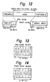
- Fig. 12 is a diagram illustrating the data structure of an audio area of a track, also referred to as an audio sector, and comprising a preamble, a data portion, and a postamble.
- the preamble has 500 bits and consists of a run-up area of 400 bits used for a run-up pattern for a phase locked loop and two pre-sync blocks used to pre-detect an audio sync block.
- the data portion consists of audio data of 10500 bits.
- the postamble has 550 bits and consists of one post-sync block, representing the end of the audio sector with the sync number of the ID, and a guard area of 500 bits used to prevent an audio sector that is after- recorded from entering the next video sector.
- Figs. 13 and 14 are diagrams illustrating the data structure of a pre-sync block and a post-sync block, respectively.
- Each pre-sync block and post-sync block has six bytes.
- the sixth byte of the pre-sync block is an SP/LP identifying byte. When the value of the SP/LP identifying byte is FFh, it represents the SP mode. When the value of the SP/LP identifying byte is 00h, it represents the LP mode.
- the sixth byte of the post-sync block is dummy data, FFh.
- the SP/LP identifying byte is also present in the TIA area as an SP/LP flag.
- the SP/LP identifying byte of the pre-sync block is used as a backup of the SP/LP flag in the TIA area. In other words, when the value of the TIA area can be read, it is used. Otherwise, the SP/LP identifying byte of the pre-sync block is used.
- Six bytes of each of the pre-sync block and post-sync block are recorded after 24-25 conversion is performed.
- the 24-25 conversion is a modulating system in which data of 24 bytes is converted into data of 25 bytes.
- Post-sync block (6 x 1 x 8 x 25)/24 50 bits
- Fig. 15 is a diagram illustrating the data structure of one of the fourteen sync blocks in the audio data portion of the audio area of a track shown in Fig. 12, also referred to as an audio sync block.
- An audio sync block has 90 bytes. The first five bytes of the audio sync block have the same structure as those of the pre-sync block and the post-sync block.
- a data portion of an audio sync block has 77 bytes that are protected by a horizontal parity C1 (eight bytes) and a vertical parity C2 (five sync blocks). These audio sync blocks are recorded after the 24-25 conversion is performed.
- the first five bytes of the data portion are used for AAUX and comprise one pack.
- Each track has nine packs.
- Numbers 0 to 8 in Fig. 15 represent pack numbers of the track.
- Fig. 16 is a schematic diagram showing the portion of AAUX arranged in the track direction. Audio data and sub-code data are recorded and reproduced as video frames.
- numbers 50 to 55 represent values of pack headers (in hexadecimal notation). As shown in Fig. 16, the same pack is redundantly written in each of 10 tracks for error protection. Thus, the data in the main area can be reproduced even if horizontal scratches and channel clogging take place in transporting the tape.
- the portion to which the pack headers are written is referred to as a main area, used for storing essential items necessary for reproducing the audio data, such as sampling frequency and quantizing bit number.
- the remaining packs are successively connected and used as an optional area.
- the remaining packs are connected in the arrow direction as in a, b, c, d, e, f, g, h, ..., skipping the packs in the main area.
- One video frame has 30 packs (525 lines/60 Hz system)or 36 packs (625 lines/50 Hz system) in the optional area.
- packs can be freely selected from the pack header table corresponding to each particular digital VCR format.
- Fig. 17 is a diagram illustrating the data structure of a video area of a track, also referred to as a video sector, and comprising a preamble, a video data portion of 149 sync blocks, and a postamble.
- the video sector preamble and postamble data structures are as shown in Figs. 13 and 14. However, the number of bits of the guard area of the video sector postamble is larger than that of the audio sector postamble.
- Fig. 18 is a diagram illustrating the data structure of one of the 149 sync blocks in the video data portion of the video area of a track shown in Fig. 17, also referred to as a video sync block.
- one video sync block has 90 bytes.
- the first five bytes of the video sync block have the same structure as those of the pre-sync block and the post-sync block.
- the video sync block data portion has 77 bytes that are protected by a horizontal parity C1 (eight bytes) and a vertical parity C2 (11 sync blocks).
- the video sync blocks are recorded after the 24-25 conversion is performed.
- Fig. 19 is a diagram illustrating a vertical arrangement of 149 sync blocks in the video data portion of the video area of a track shown in Fig. 17.
- Two upper sync blocks and one sync block that just precedes the C2 parity are sync blocks dedicated for VAUX. Data of 77 bytes is used as VAUX data.
- Each of BUF 0 to BUF 26 represents a buffering unit.
- One buffering unit is composed of five sync blocks.
- Each track has 27 buffering units. Thus, 10 tracks, which is one video frame, have 270 buffering units.
- a valid image area is extracted from image data for one frame and then sampled.
- the resultant digital data is shuffled and 270 groups are collected from various portions of the real image.
- One of the 270 groups is a buffering unit.
- Each group is compressed corresponding to a compressing technique such as DCT technique, quantizing technique, or variable length code encoding technique in such a manner that the amount of data representing all of the groups is a predetermined compressing value.
- a quantizing step of which the amount of generated data is the desired value or less is determined and used to encode the data.
- the generated encoded data is packed in one buffering block, which has five syncs.
- Fig. 20 is a diagram illustrating the data structure of a sub-code area of a track, also referred to as a sub-code sector, and comprising a preamble, a sub-code data portion , and a postamble.
- the sub-code sector preamble and postamble data structures do not have a pre-sync block and a post-sync block, and so are unlike the audio and video sector preamble and postamble.
- the length of the sub-code sector is shorter than that of each of other sectors because the sub-code sector is used frequently for writing an index, an up to 200 times high speed searching operation, or the like.
- the sub-code sector is formed at the last portion of the track, it is affected by an error that takes place at the beginning of the track.
- Fig. 21 is a diagram illustrating the data structure of one of the sync blocks in the sub-code data portion of the sub-code area of a track shown in Fig. 20, also referred to as a sub-code sync block.
- the length of the sub-code sync block is 12 bytes.
- the structure of the first five bytes of the sub-code sync block is the same as that of the audio-sync block and the video-sync block.
- the next portion of five bytes is a data portion that comprises packs.
- the horizontal parity C1 has two bytes and protects the data portion. Unlike with the audio sector and the video sector, in the sub-code sector, a product code structure using C1 and C2 is not employed.
- Each track has 12 sub-code sync blocks.
- the sub-code sync blocks are recorded after the 24-25 conversion is performed.
- Fig. 22 is a block diagram of a recording portion of a digital VCR in which the present invention is applied.
- the digital luminance signal (Y), and the color difference signals (R - Y) and (B - Y) are compressed and recorded on the video sector.
- the digital audio signal is recorded on the audio sector.
- VAUX and AAUX are recorded in a pack structure.
- Antenna 1 of Fig. 22 receives a broadcast television signal, and supplies it to tuner 2 which demodulates the TV signal into a composite color video signal (corresponding to such as NTSC system or PAL system) and an audio signal.
- Tuner 2 supplies the composite video signal to a switch 3a, and supplies the audio signal to a switch 3b.
- External video input terminal 4 receives an analog composite video color video signal and supplies it to the switch 3a.
- External audio input terminal 5 receives an analog audio signal and supplies it to the switch 3b.
- the switch 3a selects one of the composite video signal received from the tuner portion 2 and the composite video signal received from the external video input terminal 4.
- the output of the switch 3a is supplied to a Y/C separating circuit 6 and a synchronization separating circuit 11.
- the Y/C separating circuit 6 separates a luminance signal (Y) and color difference signals (R - Y) and (B - Y) from the composite video signal, and supplies these signals to low pass filters 7a, 7b, and 7c, respectively, which limit the band of the input signal so as to remove a loop-back distortion.
- the cut-off frequencies of the low pass filters 7a, 7b, and 7c are 5.75 MHz, 1.45 MHz and 1.45 MHz, respectively, in the NTSC 4:1:1 system.
- the cut-off frequencies are changed if a different system is used, such as a PAL or SECAM 4:2:0 system.
- A/D converters 8a, 8b, and 8c are adapted to receive the low pass filtered signals and to sample the luminance signal (Y) at a sampling frequency of 13.5 MHz (4x rate), the color difference signal (R - Y) at a sampling frequency of 3.375 MHz (1x rate), and the color difference signal (B - Y) at a sampling frequency of 3.375 MHz (1x rate), respectively, in accordance with clock signals supplied from phase locked loop (PLL) circuit 12 and frequency divider 13.
- PLL phase locked loop
- the synchronization separating circuit 11 produces a vertical synchronization signal (V sync) and a horizontal synchronization signal (H sync) and supplies these signals to PLL circuit 12 which generates a clock signal at the 4x rate sampling frequency 13.5 MHz that is locked to the input video signal and applies the 13.5 MHz clock signal to the A/D converter 8a and to the frequency divider 13.
- the frequency divider 13 generates a clock signal at 1/4 of the 13.5 MHz frequency, that is, a 1x rate sampling clock signal at 3.375 MHz, and applies the 1x rate clock signal to the A/D converters 8b and 8c.
- Digital component video signals (Y), (R - Y), and (B - Y) are supplied from the A/D converters 8a, 8b, and 8c to blocking circuit 9 which converts the raster scanned data into blocks of eight samples x eight lines and supplies the blocked video data to shuffling circuit 10.
- the shuffling circuit 10 shuffles the blocks. The shuffling process is performed so as to prevent data recorded on the tape from being lost due to head clogging and horizontal scratches of the tape.
- the shuffling circuit 10 changes the order of the blocks so that the luminance signal and the color difference signals can be more readily processed in subsequent circuits.
- the shuffled blocks are supplied to a data compressing and encoding portion 14, comprising a compressing circuit that performs DCT compression, an estimator that determines whether the data has been compressed to a predetermined level, and a quantizing device that quantizes the compressed data with a quantizing step corresponding to the determination by the estimator.
- the compressed video data is packed in a predetermined sync block by a framing circuit 15 according to a predetermined rule.
- the output of the framing circuit 15 is supplied to a combining circuit 16.
- Switch 3b selects the audio signal received from the tuner 2 or the audio signal received from the external audio signal input terminal 5, and supplies the selected analog audio signal to an A/D converter 21 that converts the selected analog audio signal into digital audio signal and applies the digital audio signal to a shuffling circuit 22.
- the shuffling circuit 22 shuffles the digital audio data.
- the output of the shuffling circuit 22 is supplied to a framing circuit 23.
- the framing circuit 23 packs the audio data in an audio sync block.
- the output of the framing circuit 23 is supplied to a combining circuit 24.
- Mode process microcomputer 34 that manages the modes of the VCR includes a user interface.
- the mode process microcomputer 34 operates corresponding to a field frequency of the TV image (60 Hz or 50 Hz).
- the mode process microcomputer 34 generates pack data of video auxiliary data VAUX, audio auxiliary data AAUX, and sub-code.
- Signal processing microcomputer 20 operates in synchronization with the rotation of a drum, namely, at 9000 rpm and 150 Hz.
- Signal processing microcomputer 20 generates video auxiliary data (VAUX), audio auxiliary data (AAUX), sub-code data, an absolute track number contained in a "title end" pack and a time title code (TTC) stored in the sub-code.
- VAUX video auxiliary data
- AAUX audio auxiliary data
- sub-code data an absolute track number contained in a "title end" pack
- TTC time title code
- the video auxiliary data VAUX is supplied to a VAUX circuit 17.
- the audio auxiliary data AAUX is supplied to an AAUX circuit 19.
- Combining circuit 16 combines the output of a framing circuit 15 and the VAUX data from circuit 17.
- Combining circuit 24 combines the output of a framing circuit 23 and the AAUX data .from circuit 19. The outputs of the combining circuits 16 and 24 are respectively supplied as VDATA and ADATA to a switch 26.
- a sub-code circuit 18 generates data SID of the ID portion, AP3, and sub-code pack data SDATA corresponding to the output of the signal processing microcomputer 20.
- the generated data are supplied to a switch 26.
- Sync generating circuit 25 generates each ID portion of audio and video sync blocks including AP1 and AP2 for each ID portion, pre-sync, and post-sync and supplies the generated data to a switch 26.
- the switch 26 selects one of the outputs of the circuit 25, ADATA, VDATA, SID, and SDATA at a predetermined timing.
- the output of the switch circuit 26 is supplied to an error correction code generating circuit 27 which adds a predetermined parity to the output of the switch circuit 26 and supplies the parity added information to a randomizing circuit 29.
- the randomizing circuit 29 randomizes the output of the error correction code generating circuit 27 to prevent an occurrence of a string of data having the same value (zero or one) and exceeding a predetermined length.
- the output of the randomizing circuit 29 is supplied to a 24/25 converting circuit 30 that converts 24-bit data into 25-bit data so as to remove a DC component for magnetic recording and reproducing operation.
- PRIV partial response, class 4
- (1/1-D2) (not shown) suitable for digital recording is performed.
- the output of the 24/25 converting circuit 30 is supplied to a combining circuit 31 which combines the output of the 24/25 converting circuit and a sync pattern of audio, video, and sub-code.
- the output of the combining circuit 31 is supplied to a switch 32.
- the mode process microcomputer 34 applies data APT, SP/LP, and PF to an ITI circuit 33 which generates ITI sector data and supplies the ITI sector data to switch 32.
- the switch 32 selects one of the output of combining circuit 31, the ITI sector data and an amble pattern at a predetermined timing.
- the data selected by the switch 32 is supplied to a switch 35 which forwards the selected data to a head amplifier 36a or a head amplifier 36b at a head switching timing.
- the amplifiers 36a and 36b amplify the selected data and apply the amplified data to heads 37a and 37b, respectively.
- the VCR includes an external switch block 40 employed by a use to select various modes such as recording and reproducing.
- the switch block 40 includes an SP/LP record mode setting switch.
- the switch signals of the switch block 40 are supplied to a mechanical control microcomputer 28 and the signal processing microcomputer 20.
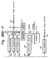
- Fig. 23 is a block diagram of AAUX pack data generating circuitry. Circuits 201-207 may be microcomputer programs executed by mode process microcomputer 34.
- Main area data collecting and generating circuit 201 receives serial copy management system data (SCMS) from a digital bus and audio mode data, sampling frequency (SMP), number of quantizing bits (QU) and CP from a tuner and generates a main area data group assembled in a bit/byte structure of a main pack.
- the main area data group includes a multilingual indication, discussed in detail below.
- Switch 202 adds an appropriate main area pack header to the main area data group and supplies the resultant data through a switch 206 to a parallel-to-serial (PS) converting circuit 208.
- PS parallel-to-serial
- Optional area data collecting circuit 203 receives a title of a digital audio music program of a PCM broadcast along with a title of a TV program from a tuner and generates an optional area data group.
- digital audio signals of so-called A mode and B mode received from the tuner a sampling frequency, the number of quantizing bits, and so forth may be predetermined.
- AAUX closed caption pack 55h
- Audio information is extracted by a decoder 210.
- the audio information is stored in each pack of addresses (50h) and (51h).
- a pack recorded in the optional area may differ by type of VCR.
- Setting circuit 204 produces an optional area pack header and supplies the header to switch 205 which adds it to the optional area data group and supplies the resultant data through switch 206 to PS converting circuit 208 in accordance with timing signals provided by a timing adjusting circuit 207.
- the PS converting circuit 208 converts the AAUX data into serial data and supplies the serial data to a signal processing microcomputer 20 in a predetermined inter-microcomputer communication protocol.
- the signal processing microcomputer 20 converts the serial data to parallel data and stores it in a buffer.
- the parallel data is successively read and sent to a combining circuit 24 at a predetermined timing.
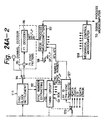
- Figs. 24A and 24B are a block diagram of a reproducing portion of a digital VCR in which the present invention is applied.
- Heads 101a and 101b produce reproduced data signals and supply these signals to head amplifiers 102a and 102b, respectively, which amplify the reproduced data signals and apply the amplified signals to switch 103.
- the data selected by the switch 103 is supplied to an equalizer circuit 104 which performs an inverse emphasis process.
- an emphasis process for example, partial response, class 4 is performed.
- the output of the equalizer circuit 104 is supplied to an A/D converter 106 and a clock extracting circuit 105.
- the clock extracting circuit 105 extracts a clock signal from the reproduced signals.
- the output of the equalizer circuit 104 is digitized by an A/D converter 106 at the a timing determined by the extracted clock signal.
- the resultant one-bit data is written to a first in first out memory (FIFO) 107, and read out therefrom to a sync pattern detecting circuit 108.
- FIFO first in first out memory
- a sync pattern of each area is supplied to the sync pattern detecting circuit 108 through a switch 109.
- the switch position of the switch 109 is changed corresponding to a timing circuit 113.
- the sync pattern detecting circuit 108 has a so-called flywheel construction so as to prevent an error from taking place. In the flywheel construction, whenever a sync pattern is detected, it is determined whether or not the same sync pattern has been received during an interval of a predetermined length. When the determined result is yes, for example, three times or more, the circuit 108 detects that the sync pattern is reliable.
- the shift amount for forming one sync block extracted from each stage of the FIFO 107 is determined.
- required bits are supplied through a switch 110 to a sync block settlement latch 111.
- the sync number of the obtained sync is extracted by an extracting circuit 112 and supplied to a timing circuit 113. Since the head position on the track corresponds to the sync number, the switch positions of the switches 109 and 114 are changed.
- the switch 114 In the case of the ITI sector, the switch 114 is placed at the lower position.
- a separating circuit 115 separates an ITI sync pattern.
- the ITI sync pattern is supplied to an ITI decoder 116.
- encoded data In the ITI area, encoded data is recorded. Thus, by decoding the data in the ITI area, data of APT, SP/LP, and PF can be obtained.
- the decoded data is supplied to a mode process microcomputer 117 that determines the operation mode and the like of the VCR and is connected to an external operation key 118.
- the mode process microcomputer 117 controls the reproducing portion of the VCR in association with a mechanical control microcomputer 128 and a signal process microcomputer 151.
- the switch 114 is placed in the upper position.
- a separating circuit 122 extracts a sync pattern of each sector and supplies the extracted sync pattern to a derandomizing circuit 124 through a 24/25 inverse converting circuit 123 so as to restore an original data sequence.
- the restored data is supplied to an error correcting circuit 125.
- the error correcting circuit 125 detects and corrects erroneous data. When data that cannot be corrected is present, an error flag is added thereto. The output of circuit 125 is applied to switch 126.
- Circuit 127 processes the ID portion of the A/V sector, the pre-sync, and the post-sync.
- the circuit 127 extracts the sync number, track number, and SP/LP stored in each sync of pre-sync and post-sync and supplies the extracted data to timing circuit 113 that generates various timing signals.
- the circuit 127 also extracts application IDs AP1 and AP2 and supplies them to the mode process microcomputer 117 which determines the format corresponding to AP1 and AP2.
- AP1 and AP2 000
- the mode process microcomputer 117 defines AREA 2 (see Figs. 7 and 9B) as an image data area and assumes that normal operation will occur. Otherwise, the mode process microcomputer performs a warning process.
- the mode process microcomputer 117 determines SP/LP information stored in the ITI area. In a TIA area of the ITI area, the SP/LP information is written three times. By the rule of majority, the reliability of the SP/LP information is improved. In the audio sector and video sector, there are a total of four sync blocks in which the SP/LP information is written. By the rule of majority, the reliability is further improved. If the SP/LP information written to the ITI area does not accord with that written to the pre-sync blocks, the SP/LP information written to the ITI area is used with higher precedence.
- the reproduced data of a video sector is separated into video data and VAUX data by switch 129 shown in Fig. 24B.
- the video data is supplied to a deframing circuit 130 along with the error flag.
- the deframing circuit 130 deframes the video data and supplies image data is supplied to a data decompressing and decoding portion comprising dequantizing circuit 131 and decompressing circuit 132.
- the circuit 131 inverse quantizes the image data from deframing circuit 130, and supplies dequantized data to circuit 132 which inverse orthogonal transforms the dequantized data to produce decompressed data and supplies the decompressed data to a deshuffling circuit 133 that deshuffles the decompressed data and applies the deshuffled data as luminance and color difference data to block desegmenting circuit 134 that restores the original image sequence.
- the desegmented luminance and color difference signals are supplied to D/A converters 135a, 135b, and 135c, respectively, which generate analog signals in accordance with clock signals at 13.5 MHz, 3.375 MHz and 3.375 MHz, respectively (for NTSC signals).
- Oscillator 139 produces the 13.5 MHz clock signal based on the output of crystal oscillator 138, and supplies the 13.5 MHz clock signal to frequency divider 140 which produces therefrom clock signals at 6.75 MHz and 3.375 MHz.
- Oscillator 139 also applies the 13.5 MHz signal to synchronization signal generating circuit 141, which generates synchronization signals such as vertical and horizontal synchronization signals according to the NTSC standard, and provides the synchronization signals to combining circuit 137.
- the analog luminance and color difference signals are supplied to Y/C combining circuit 136 which combines them into a combined signal, and provides the combined signal to combining circuit 137.
- the combining circuit 137 combines the combined signal and synchronization signals and supplies the resulting composite. analog video signal to output terminal 142.
- Data reproduced from the audio sector is supplied to a switch 143 that separates the data into audio data and AAUX data.
- the audio data is supplied to a deshuffling circuit 145.
- the deshuffling circuit 145 restores the original time base of the audio data. At this point, when necessary, the audio data is interpolated in accordance with the error flag.
- the output of the deshuffling circuit 145 is supplied to a D/A converter 146 which restores an analog audio signal and supplies it to an output terminal 147 in synchronization with the video data.
- VAUX and AAUX data selected by the switches 129 and 143 are supplied to a VAUX circuit 148 and an AAUX circuit 150, respectively.
- the VAUX circuit 148 and the AAUX circuit 150 perform pre-processing such as rule-of-majority processing for multiple write situations in accordance with the error flag.
- the ID portion and the data portion of the sub-code sector are supplied to a sub-code circuit 149.
- the sub-code circuit 149 performs a pre-processing such as the rule-of-majority process in accordance with the error flag.
- the output of the sub-code circuit 149 is supplied to a signal process microcomputer 151 that performs a final reading operation.
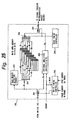
- Fig. 25 is a block diagram of an AAUX pack data reproducing circuit 150.
- the AAUX data received through the switch 143 is divided into main area data and optional area data by a switch 301 controlled by a write side controller 302 at a predetermined timing.
- Pack header detecting circuit 303 reads the main area pack data header and controls switch 304 in accordance therewith.
- the pack data does not contain an error
- the pack data is written to a main area memory 305 which stores, for each data word, data of eight bits and an error flag of one bit.
- the initial setting of the data content for each video frame in the main area memory 305 is, for example, "1" (no information).
- no action is performed.
- the error-free data and error flag "0" are written. Since the same pack is written to the main area 10 (NTSC) or 12 (PAL) times, when one video frame is completed, data with error flag "1" is finally recognized as erroneous data.
- the error flag is written to an optional area FIFO 308 along with the data.
- the contents of the memory 305 and the FIFO 308 are supplied to a signal process microcomputer 151 through switches 306 and 307 controlled by a read timing controller 309.
- the signal process microcomputer 151 analyzes data for the main area and the optional area corresponding to the received pack data and error flag. After the parallel data is converted into serial data, it is supplied to a mode process microcomputer 117.
- the mode process microcomputer 117 restores parallel data, decombines pack data, and analyzes it.
- Fig. 15 shows nine sync blocks 0 ... 8 in the audio data portion of the audio area of a track shown in Fig. 12, and that each of these nine sync blocks includes a five byte AAUX pack. As shown in Fig. 10, the first byte (PCO) of each pack is a header.
- the data byte PC1 includes the following information:
- Fig. 27 is a table showing the values of the AUDIO MODE information in header byte PC2.
- the definitions for the table of Fig. 27 are similar to the definitions for the table of Fig. 2, and also include the following:
- Figs. 28A-28E are diagrams illustrating the speaker positions of each channel of each stereo mode. The listener position is assumed to be at the center of each circle.
- Fig. 28A shows 3/0 stereo mode in which three speakers L, C and R are in front of the listener and there is no speaker behind the listener.
- the center speaker is positioned directly in front of the listener.
- the right and left speakers are positioned 45 degrees away from the center speaker.
- Fig. 28B shows 3/1 stereo mode in which three speakers of L, C and R are in front of the listener and there is a surround speaker S behind the listener.
- the surround speaker is positioned directly behind the listener.
- Fig. 28C shows 2/2 stereo mode in which two speakers L, R are in front of the listener and two speakers LS (Left Surround) and RS (Right Surround) are positioned at the sides of the listener.
- Fig. 28D shows 3/4 + Wo stereo mode in which three speakers L, C and R are in front of the listener and four speakers Ls1, Ls2, Rs1, Rs2 are positioned behind the listener. Since the human ears cannot sense the direction of low frequency sound, the position of the woofer speaker does not matter.
- Fig. 28E shows 5/2 + Wo stereo mode in which five speakers L, Lc, C, Rc, R are in front of the listener and two speakers Ls, Rs are behind the listener.
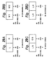
- Figs. 29A-29D and 30A-30H are diagrams to which reference is made in explaining audio control data including AUDIO MODE, PA, SM and CHN information for SD and HD signals, respectively.
- SM 0 in all cases because standard definition signals are illustrated.
- Fig. 29A shows the audio control data in the case that a stereo signal is recorded in stereo two-channel mode. Since Left audio signal and Right audio signal are outputted at the same time, PA is "0".
- Fig. 29B shows an example in the case that two monaural signals with different contents (for example, bilingual program) are recorded. Since the two monaural signals may be outputted separately, PA is "1".
- Fig. 29C shows an example in the case that 3/1 stereo signals are recorded in the SD four-channel mode. Since LR (Left and Right audio signal) and CS (Center and Surround audio signal) may be outputted at the same time, PA is "0". Since the two audio signals are recorded in one audio block spanning five or six tracks, CHN is "01".
- Fig. 29D shows an example in the case that two independent stereo audio signals (LR and L'R') are recorded. Since the two stereo audio signals are outputted separately, PA is "1". CHN is "01" because the two audio signals are recorded in one audio block.
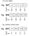
- Figs. 30A-30C the HD 4-channel mode is illustrated.
- CHN "00" in these cases because one audio signal is recorded within one audio block.
- SM 0 in these cases because the audio signal of front two audio blocks and the audio signal of rear two audio blocks are outputted separately.
- Fig. 30A shows an example in the case that a stereo signal is recorded using front two audio blocks in HD 4 channel mode. Since L (Left audio signal) and R (Right audio signal) may be outputted at the same time, PA is "0".
- Fig. 30B shows an example in the case that two stereo signals LR and L'R' are recorded in HD 4 channel mode. Since L and R of front two audio blocks are outputted at the same time, PA of front two audio blocks are "0". Since L' and R' of rear two audio blocks are outputted at the same time, PA of rear two audio blocks are "0".
- Fig. 30C shows an example in the case that a stereo signal and two monaural signals are recorded in HD 4 channel mode. Since L and R are outputted at the same time, PA of front two channels are "0". Since two monaural audio signal are outputted separately, PA of rear two audio blocks are "1".
- Figs. 30D and 30E the HD lumped mode (4 ch) is illustrated.
- PA "1" (no information).
- SM in these cases because the audio signals are all outputted at the same time, that is, they are lumped.
- Fig. 30D shows an example in the case that a 3/0 stereo signal is recorded in HD 4-channel mode.
- Fig. 30E shows an example in the case that a 3/1 stereo signal is recorded in HD 4-channel mode.
- Figs. 30F and 30G the HD 8-channel mode is illustrated.
- Fig. 30H illustrates the HD lumped mode (8 ch).
- Fig. 31 is a table showing combinations of the control data SM, CHN and PA recorded in the AAUX area of a track for various types of audio signals.
- Fig. 26 shows an AAUX pack having one multilingual bit ML in the data byte PC3.
- the one bit multilingual flag ML is defined as follows:
- Fig. 32A shows an AAUX pack having two multilingual bits ML2, ML1 in the data byte PC3.
- the two-bit multilingual flag ML is defined as follows:
- Fig. 32B shows an AAUX pack having three multilingual bits ML2, ML1, ML0.
- the bits ML2, ML1 are in the data byte PC3.
- the bit ML0 is in the data byte PC1.
- the three-bit multilingual flag ML is defined as follows:
- Figs. 33-35 show examples of using a one bit, two bit and three bit multilingual flag, respectively.
- Figs. 33A-33G show examples of using a one bit multilingual flag.
- Fig. 33A shows an example in which two monaural signals M1 and M2 have been recorded in an SD four-channel format.
- M1 is a music signal
- M2 is a narration signal
- ML 1.
- Fig. 33B shows an example in which two monaural signals M1 and M2 have been recorded in an SD four-channel format.
- M1 is a Japanese audio
- M2 is an English audio (in the case of bilingual audio)
- ML 0.
- the Japanese sound that is a main sound has been recorded on five tracks prior to the English sound. This relation applies to other recording examples.
- channel selector 180 for selecting a channel of an audio signal is disposed between the deshuffling circuit 145 of the VCR reproducing circuit and the D/A converting circuit 146 shown in Fig. 24B.
- the selector 180 indicates to the user whether a multilingual signal has been recorded by activating display 182, which may be an alphanumeric display or a lamp on a console or remote device. The user selects among the available channels using switch block 181 or another appropriate data entry device.
- the user can easily determine whether or not signals have been multilingually recorded corresponding to the multilingual flag ML. For example, when the value of the flag ML is displayed, the user can know whether or not the signals have been multilingually recorded and can select a desired channel.
- the main audio has been recorded prior to the sub audio in one video frame.
- the present invention is not limited to such a scheme. Instead, the user can allocate the record position of each language (for example, the first channel for English, the second channel for French).
- both an automatic mode for recording the main audio prior to the sub audio and a manual mode for allowing the user to allocate the position of each language can be provided.
- Fig. 33C shows an example in which four monaural signals M1, M2, M3, M4 have been recorded in an SD four-channel format.
- M1 is a Japanese sound and M2 is an English sound
- ML 0 for M1 and M2 (channels 1 and 2).
- M3 is a classic music sound and M4 is a rock music sound
- ML 1 for M3 and M4 (channels 3 and 4).
- Fig. 33D shows an example in which two stereo signals L1, R1 and L2, R2 have been recorded in an SD four-channel format.
- L1 and R1 are classical music
- ML 1 for L1 and R1.
- L2 and R2 are rock music
- ML 1 for L2 and R2.
- Fig. 33E shows another example in which two stereo signals L1, R1 and L2, R2 have been recorded in an SD four-channel format.
- L1 and R1 are Japanese movie speech
- ML 0 for L1 and R1.
- L2 and R2 are English movie speech
- ML 0 for L2 and R2.
- the Japanese speech (main audio) has been recorded before the English speech (sub audio).
- Fig. 33F shows an example of an HD eight-channel format.
- L1 and R1 are English movie speech
- ML 0 for L1 and R1.
- L2 and R2 are French movie speech
- ML 0 for L2 and R2.
- L3 and R3 are Dutch movie speech
- ML O for L3 and R3.
- L4 and R4 are German movie speech sounds
- ML 0 for L4 and R4.
- Fig. 33G shows another example of an HD eight-channel format in which two stereo signals and four monaural signals have been recorded.
- L1 and R1 are English movie speech
- ML 0 for L1 and R1 (channels A and B).
- L2 and R2 are classic music sounds
- ML 1 for L2 and R2 (channels C and D).
- the English speech is treated as the main audio.
- the number of languages recorded in one video frame can be determined. Audio with a record number selected by the user can be automatically selected and reproduced. When the user selects the second audio, the language of the second audio is selected and reproduced.
- Figs. 34A-34D show examples of using a two bit multilingual flag in an HD eight-channel format.
- Fig. 34A shows an example in which four language movie speech of English, French, Dutch and German have been recorded.
- all the two-bit multilingual flags ML are "00" indicating that although the same program has been multilingually recorded, there is no other program that has been multilingually recorded.
- Fig. 34B shows an example of which trilingual movie speech of English, Dutch, and German and classic music (L2 and R2) have been recorded.
- the multilingual flags for L2 and R2 are "11" indicating that the same program has not been multilingually recorded or it is unknown.
- the other multilingual flags are "00".
- Fig. 34C shows an example in which bilingual movie speech of Japanese and English have been recorded as L1 and R1 and L2 and R2, respectively, and Japanese news program sounds and English new program sounds have been recorded as L3 and R3 and L4 and R4, respectively.
- the multilingual flags ML for all channels are "01" indicating that although the same program has been multilingually recorded, another program has been multilingually recorded.
- Fig. 34D shows an example in which bilingual movie speech of Japanese and English have been recorded as L1 and R1 and L2 and R2, respectively; a bilingual news program in Japanese and English has been recorded as M3 and M4, respectively; and bilingual comic talk in Japanese and English have been recorded as M3 and M4, respectively.
- the main audio has been recorded prior to the sub audio.
- the multilingual flags ML for all channels are "10" indicating that although the same program has been multilingually recorded, there are two or more different programs that have been multilingually recorded.
- Figs. 35A-35F show examples of using a three bit multilingual flag in an HD eight-channel format.
- Fig. 35A shows an example in which four language movie speech in English, French, Dutch, and German have been recorded as stereo signals.
- ML 010 for all the channels indicating that there are three channels on which the same program has been recorded in different languages.
- Fig. 35B is an example in which three language movie speech in English, French and German have been recorded as stereo signals and classic music has been recorded as L2 and R2.
- ML 111 for channels of the classic music indicating that the same program has not been multilingually recorded or it is unknown.
- ML 001 for the other channels indicating that there are two channels on which the same program has been recorded in different languages.
- Fig. 35C shows an example in which bilingual movie speech in Japanese and English have been recorded as L1 and R1 and L2 and R2, respectively and bilingual news programs in Japanese and English have been recorded as L3 and R3 and L4 and R4, respectively.
- the multilingual flags ML 000 for all the channels indicating that there is one channel on which the same program has been recorded in a different language.
- Fig. 35D shows an example in which bilingual movie speech in Japanese and English have been recorded as L1 and R1 and L2 and R2, respectively, bilingual news programs in Japanese and English have been recorded as M1 and M2, respectively, and bilingual comic talk programs in Japanese and English have been recorded as M3 and M4, respectively.
- the multilingual flags ML 000 for all the channels indicating that there is one channel on which the same program has been recorded in a different language.
- Fig. 35E shows an example in which monaural signals M1 to M8 have been recorded on eight channels.
- Baseball broadcast program audio consisting of Japanese general commentary, Japanese specific team commentary, English general commentary, and English specific team commentary have been recorded as M1, M2, M3 and M4, respectively.
- the multilingual flags ML 010 for these signals (channels A-D) indicating that there are three channels on which the same program has been recorded in different languages.
- News in Japanese and English is recorded as M5 and M6, while comic speech in Japanese and English is recorded as M7 and M8.
- the multilingual flags ML 000 for these signals (channels E to H) indicating that there are two channels on which the same program has been recorded in different languages.
- Fig. 35F shows another example in which monaural signals M1 to M8 have been recorded on eight channels.
- Multilingual movie speech have been recorded as monaural signals M1 to M8.
- a Japanese movie speech that is a main sound has been recorded prior to other language movie speech sounds.
- the other language movie speech sounds of English, German, Dutch, French, Russian, Italian and Spanish have been recorded as M2 to M8, respectively.
- Fig. 36 is a flowchart illustrating operation of an apparatus embodying the present invention with a multilingual indication.
- the flowchart of Fig. 36 may represent a program executed by the VCR of Fig. 24. It is assumed that the system has advised the user of the number of unrelated programs represented in the recorded audio channels, and that the user has selected one of these programs in accordance with a technique which is not part of the present invention. That is, the flowchart of Fig. 36 relates to the situation where a selected program may or may not have multilingual channels associated therewith.
- N is initialized to a value of 1.
- the parameter N indicates which audio channel of a set of related audio channels is being evaluated.
- the maximum value of N is four (e.g., a program with audio in four languages), whereas in an eight-channel system, the maximum value of N is eight (e.g., a program with audio in eight languages).
- the Nth audio block is reproduced.
- the multilingual display is activated so that the user understands that at least one other language or commentary for the program being viewed is available.
- the multilingual display may be, for example, a lamp on a console or remote device, or a message displayed on a television set.
- step 650 it is determined whether the user has selected the next channel, such as by depressing a button on a hand-held remote control unit, or entered a specific channel number. If not, the user is assumed to be satisfied with the currently reproduced language or commentary and, at step 680, the program terminates.
- N is incremented and the program returns to step 620.
- the just incremented value of N exceeds the number of related audio channels for the selected program, then the number of related audio channels for the selected program is subtracted from the just incremented value of N, thereby allowing the user to loop through the multilingual channels for the selected program.
- the user determines whether or not transmitted digital audio signals have been multilingually recorded.
- the user can know the languages of recorded sounds without need to reproduce all channels thereof.
- the main sound can be automatically and initially reproduced without need to change channels.
- the user can select channels for languages which have been multilingually recorded, audio channels to be initially reproduced can be selected.
Landscapes
- Engineering & Computer Science (AREA)
- Signal Processing (AREA)
- Multimedia (AREA)
- Signal Processing For Digital Recording And Reproducing (AREA)
- Television Signal Processing For Recording (AREA)
- Television Receiver Circuits (AREA)
- Stereophonic System (AREA)
Claims (18)
- Verfahren zur Aufzeichnung eines aus einer Vielzahl von Audiokanälen bestehenden digitalen Audiosignals auf einem Aufzeichnungsträger, wobei die betreffenden Audiokanäle einen Haupt- und einen Sub-Audiokanal in Verbindung mit einem gemeinsamen Programm enthalten, umfassend die Verfahrensschritte:dadurch gekennzeichnet, dass die Audio-Hilfsdaten eine Anzeige dafür enthalten, dass zumindest zwei der genannten Audiokanäle einem gemeinsamen Programm zugeordnet sind,Empfangen des genannten digitalen Audiosignals,Erzeugen von Audio-Hilfsdaten,Formatieren des betreffenden digitalen Audiosignals und der betreffenden Audio-Hilfsdatenund Aufzeichnen des genannten formatierten digitalen Audiosignals und der genannten Audio-Hilfsdaten als eine Vielzahl von Spuren auf dem genannten Aufzeichnungsträger,
dass das Verfahren die Bestimmung einer bevorzugten Reihenfolge umfasst, in der die genannten Haupt-Audio- und Sub-Audiokanäle aufzuzeichnen sind,
und dass der Formatierungsschritt die Schritte des Anordnens bzw. Festlegens der genannten Audio-Hilfsdaten als Packungsdaten, der Bildung eines Audiobereiches aus jeder der genannten Spuren aus den betreffenden Packungsdaten und einem zugeordneten Audiodatenteil, der die betreffenden zugeordneten Audiokanäle repräsentiert, und des Anordnens bzw. Festlegens umfasst, welcher Kanal des genannten Haupt-Audiokanals und des genannten Sub-Audiokanals zuerst in einem bestimmten Bereich auf dem Aufzeichnungsträger entsprechend der genannten bevorzugten Reihenfolge aufgezeichnet wird. - Verfahren nach Anspruch 1, wobei die Bestimmung der bevorzugten Reihenfolge, in der die genannten Haupt- und Sub-Audiokanäle aufzuzeichnen sind, den Empfang einer manuellen Anweisung der betreffenden bevorzugten Reihenfolge von einem Benutzer umfasst.
- Verfahren nach Anspruch 1 oder 2, dadurch gekennzeichnet, dass der Schritt der Erzeugung der genannten Audio-Hilfsdaten die Schritte der Bestimmung, ob die empfangenen digitalen Audiosignale mehr als ein Programm repräsentieren, welches zumindest zwei zugeordnete Audio-kanäle aufweist, und die Erzeugung der genannten Anzeige umfasst, die in den betreffenden Audio-Hilfsdaten enthalten ist, um eine Anzeige darüber einzuschließen, dass die aufzuzeichnenden digitalen Audiosignale mehr als ein Programm mit zumindest zwei Kanälen enthalten.
- Verfahren nach Anspruch 1 oder 2, dadurch gekennzeichnet, dass der Schritt der Erzeugung der genannten Audio-Hilfsdaten die Schritte des Bestimmens der Anzahl von dem genannten gemeinsamen Programm zugeordneten Audiokanälen und das Erzeugen der in den betreffenden Audio-Hilfsdaten enthaltenen Anzeige umfasst, um die betreffende Anzahl von Audiokanälen auszudrücken.
- Verfahren nach irgendeinem vorhergehenden Anspruch, umfassend die Schritte des Bestimmens einer Reihenfolge, in der die zumindest zwei Audiokanäle, die demselben Programm zugeordnet sind, aufgezeichnet sein sollten, aus den genannten digitalen Audiosignalen,
Erzeugen von Modusdaten, die kennzeichnend sind für die Reihenfolge, in der die betreffenden Audiokanäle aufgezeichnet werden,
und Bilden der genannten Audio-Modusdaten in der genannten Datenpackung als Teil der genannten Audio-Hilfsdaten. - Verfahren nach einem der Ansprüche 2 bis 5, wobei der Formatierungsschritt den Schritt der Bildung der digitalen Audiosignale entsprechend den zumindest zwei zugeordneten Audiokanälen in dem genannten zugeordneten Audiodatenteil und die Bildung der genannten Packungsdaten an einer dem genannten zugeordneten Audiodatenteil benachbarten Nebenstelle umfasst
und wobei der Aufzeichnungsschritt den Schritt des Kombinierens einer Vielzahl der genannten Audiobereiche und die Aufzeichnung der betreffenden kombinierten Audiobereiche in dem genannten bestimmten Bereich für jede der genannten Spuren umfasst. - Verfahren nach irgendeinem vorhergehenden Anspruch, wobei der Aufzeichnungsträger ein Magnetband ist.
- Verfahren zur Wiedergabe einer Vielzahl von Audiokanälen von einem digitalen Audiosignal, welches einen Haupt- und einen Sub-Audiokanal in Verbindung mit einem gemeinsamen Programm enthält, das auf einem Aufzeichnungsträger gemäß dem Aufzeichnungsverfahren nach irgendeinem der Ansprüche 1 bis 7 aufgezeichnet ist, wobei ein Kanal des genannten Haupt-Audiokanals und des genannten Sub-Audiokanals in einem bestimmten Bereich auf dem Aufzeichnungsträger entsprechend einer bevorzugten Reihenfolge zuerst aufgezeichnet ist, wobei das Wiedergabeverfahren die Verfahrensschritte umfasst:sowie Wiedergeben des ausgewählten Audiokanals.Ermitteln der Packungsdaten aus einem Audiobereich zumindest einer auf dem Aufzeichnungsträger aufgezeichneten Spur, Wiedergewinnen einer mehrsprachigen Anzeige, die anzeigt, ob zumindest zwei Audiokanäle, die verschiedene Sprachen repräsentieren, demselben Programm zugeordnet sind oder nicht, aus den Packungsdatenund auf die betreffende mehrsprachige Anzeige hin folgend Auswählen eines Kanals aus (i) dem in dem genannten bestimmten Bereich aufgezeichneten ersten Kanal des betreffenden Haupt-Audiokanals und des genannten Sub-Audiokanals und (ii) einem durch einen Benutzer ausgewählten Audiokanal, wenn die mehrsprachige Anzeige anzeigt, dass zumindest zwei Audiokanäle demselben Programm zugeordnet sind,
- Verfahren zur Wiedergabe eines Audiokanals nach Anspruch 8, wobei der Schritt der Ermittlung der Packungsdaten die Schritte des wiederholten Empfangs der Packungsdaten von einer Vielzahl aufgezeichneter Audiobereichen, die Wiedergewinnung der mehrsprachigen Anzeige aus den Packungsdaten und die Bestimmung einer aufgelösten bzw. analysierten mehrsprachigen Anzeige entsprechend einer Mehrheitsregel der mehrsprachigen Anzeige umfasst, die aus den wiederholt ermittelten Packungsdaten wiedergewonnen sind.
- Vorrichtung zur Aufzeichnung eines aus einer Vielzahl von Audiokanälen gebildeten digitalen Audiosignals auf einem Aufzeichnungsträger, wobei die betreffenden Audiokanäle einen Haupt-Audiokanal und einen Sub-Audiokanal in Verbindung mit einem gemeinsamen Programm aufweisen, umfassend
eine Einrichtung (1, 2) zum Empfang des genannten digitalen Audiosignals,
eine Einrichtung (20) zur Erzeugung von Audio-Hilfsdaten (AAUX),
eine Einrichtung (24) zum Formatieren des genannten digitalen Audiosignals und der genannten Audio-Hilfsdaten und
eine Einrichtung (34) zur Aufzeichnung des betreffenden formatierten digitalen Audiosignals und der genannten Audio-Hilfsdaten (AAUX) als eine Vielzahl von Spuren auf dem genannten Aufzeichnungsträger,
gekennzeichnet durch eine Einrichtung (34) zur Bestimmung einer bevorzugten Reihenfolge, in der die genannten Haupt-Audio- und Sub-Audiokanäle aufzuzeichnen sind,
und dadurch, dass die Audio-Hilfsdaten eine Anzeige darüber enthalten, dass zumindest zwei der genannten Audiokanäle einem gemeinsamen Programm zugeordnet sind,
und dadurch, dass die Einrichtung (34) zur Formatierung des genannten digitalen Audiosignals derart arbeitet, dass die betreffenden Audio-Hilfsdaten als Packungsdaten angeordnet werden, dass ein Audiobereich aus jeder der genannten Spuren von den genannten Packungsdaten und einem zugeordneten Audiodatenteil gebildet wird, der die betreffenden zugeordneten Audiodaten repräsentiert, und dass ein Haupt-Audiokanal oder der genannte Sub-Audiokanal angeordnet werden, um in einem bestimmten Bereich auf dem Aufzeichnungsträger gemäß der genannten bevorzugten Reihenfolge zuerst aufgezeichnet zu werden. - Vorrichtung nach Anspruch 10, wobei die genannte Einrichtung (34) zur Bestimmung einer bevorzugten Reihenfolge, in der die genannten Haupt-Audio- und die genannten Sub-Audiokanäle aufzuzeichnen sind, derart betreibbar ist, dass eine. Anweisung bezüglich der betreffenden bevorzugten Reihenfolge manuell von einem Nutzer erhalten wird.
- Vorrichtung nach Anspruch 10 oder 11, dadurch gekennzeichnet, dass die Einrichtung (34) zur Erzeugung der genannten Audio-Hilfsdaten derart arbeitet, dass bestimmt wird, ob die empfangenen digitalen Audiosignale mehr als ein Programm repräsentieren, welches zumindest zwei zugeordnete Audiokanäle aufweist, und dass die in den genannten Audio-Hilfsdaten enthaltene Anzeige erzeugt wird, um eine Anzeige darüber einzuschließen, dass die aufzuzeichnenden digitalen Audiosignale mehr als ein Programm enthalten, das zumindest zwei Kanäle aufweist.
- Vorrichtung nach Anspruch 10 oder 11, dadurch gekennzeichnet, dass die Einrichtung (24) zur Erzeugung der genannten Audio-Hilfsdaten derart arbeitet, dass die Anzahl der demselben Programm zugeordneten Kanäle bestimmt wird
und dass die in den betreffenden Audio-Hilfsdaten enthaltene Anzeige erzeugt wird, um die betreffende Anzahl der Audiokanäle wiederzugeben. - Vorrichtung nach einem der Ansprüche 10 bis 13, wobei die genannte Einrichtung (24) zur Erzeugung der genannten Audio-Hilfsdaten derart arbeitet, dass aus den genannten digitalen Audiosignalen eine Reihenfolge bestimmt wird, in der zumindest zwei Audiokanäle, die demselben Programm zugeordnet sind, aufgezeichnet sein sollten,
dass Modusdaten erzeugt werden, die kennzeichnend sind für die Reihenfolge, in der die genannten Audiokanäle aufgezeichnet werden,
und dass die genannten Audio-Modusdaten in der genannten Datenpackung als Teil der genannten Audio-Hilfsdaten gebildet werden. - Vorrichtung nach einem der Ansprüche 10 bis 14, wobei die Einrichtung (34) zur Formatierung derart arbeitet, dass die digitalen Audiosignale entsprechend den genannten zumindest zwei zugeordneten Audiokanälen in dem genannten zugeordneten Audiodatenteil gebildet werden, dass die genannten Packungsdaten an einer dem genannten zugeordneten Audiodatenteil benachbarten Nebenstelle gebildet werden
und dass die genannte Aufzeichnungseinrichtung derart arbeitet, dass eine Vielzahl der betreffenden Audiobereiche kombiniert und die betreffenden kombinierten Audiobereiche in dem genannten bestimmten Bereich für jede der genannten Spuren aufgezeichnet werden. - Vorrichtung nach einem der Ansprüche 10 bis 15, wobei der Aufzeichnungsträger ein Magnetband ist.
- Vorrichtung zur Wiedergabe einer Vielzahl von Audiokanälen von einem digitalen Audiosignal, welches einen Haupt- und einen Sub-Audiokanal in Verbindung mit einem gemeinsamen Programm enthält, das mittels einer Vorrichtung zur Aufzeichnung nach einem der Ansprüche 10 bis 16 aufgezeichnet ist, wobei ein Kanal des genannten Haupt-Audiokanals und des genannten Sub-Audiokanals in einem bestimmten Bereich auf dem genannten Aufzeichnungsträger entsprechend einer bevorzugten Reihenfolge zuerst aufgezeichnet ist, umfassend
eine Einrichtung (101a, 101b, 149) zur Ermittlung der Packungsdaten eines Audiobereiches zumindest einer auf dem Aufzeichnungsträger aufgezeichneten Spur,
eine Einrichtung (117) zur Wiedergewinnung einer mehrsprachigen Anzeige, die anzeigt, ob zumindest zwei Audiokanäle, die verschiedene Sprachen repräsentieren, demselben Programm zugeordnet sind oder nicht, aus den Packungsdaten
und eine Einrichtung (117, 151) zur Auswahl auf die betreffende mehrsprachige Anzeige hin folgend eines Kanals (i) des genannten ersten Kanals von dem Haupt-Audiokanal und dem Sub-Audiokanal, die in dem genannten bestimmten Bereich aufgezeichnet sind, und (ii) eines durch einen Benutzer ausgewählten Audiokanals, wenn die mehrsprachige Anzeige angibt, dass zumindest zwei Audiokanäle demselben Programm zugeordnet sind,
sowie eine Einrichtung zur Wiedergabe des ausgewählten Audiokanals. - Vorrichtung zur Wiedergabe eines Audiokanals nach Anspruch 17, wobei die Einrichtung (101a, 101b, 149) zur Ermittlung der Packungsdaten derart arbeitet, dass die Packungsdaten von einer Vielzahl von aufgezeichneten Audiobereichen wiederholt empfangen werden, dass aus den Packungsdaten die mehrsprachige Anzeige wiedergewonnen wird und dass eine aufgelöste bzw. analysierte mehrsprachige Anzeige gemäß einer Mehrheitsregel der aus den wiederholt ermittelten Packungsdaten wiedergewonnenen mehrsprachigen Anzeigen bestimmt wird.
Applications Claiming Priority (3)
| Application Number | Priority Date | Filing Date | Title |
|---|---|---|---|
| JP12299794 | 1994-05-12 | ||
| JP12299794A JP3477818B2 (ja) | 1994-05-12 | 1994-05-12 | ディジタルオーディオ信号伝送装置 |
| JP122997/94 | 1994-05-12 |
Publications (2)
| Publication Number | Publication Date |
|---|---|
| EP0682421A1 EP0682421A1 (de) | 1995-11-15 |
| EP0682421B1 true EP0682421B1 (de) | 2003-02-26 |
Family
ID=14849726
Family Applications (1)
| Application Number | Title | Priority Date | Filing Date |
|---|---|---|---|
| EP95303190A Expired - Lifetime EP0682421B1 (de) | 1994-05-12 | 1995-05-11 | Verfahren und Vorrichtung zum Aufzeichnen eines digitalen Audiosignals bestehend aus einer Vielzahl von Audiokanälen und Verfahren und Vorrichtung zum Wiedergeben derselben |
Country Status (5)
| Country | Link |
|---|---|
| US (1) | US6344939B2 (de) |
| EP (1) | EP0682421B1 (de) |
| JP (1) | JP3477818B2 (de) |
| KR (1) | KR100417552B1 (de) |
| DE (1) | DE69529696T2 (de) |
Families Citing this family (26)
| Publication number | Priority date | Publication date | Assignee | Title |
|---|---|---|---|---|
| US6147715A (en) | 1996-03-15 | 2000-11-14 | Index Systems, Inc. | Combination of VCR index and EPG |
| JP3357288B2 (ja) * | 1998-04-10 | 2002-12-16 | パイオニア株式会社 | 情報記録媒体及び再生装置 |
| JPH11296997A (ja) * | 1998-04-10 | 1999-10-29 | Pioneer Electron Corp | 情報記録媒体及び再生装置 |
| CN1867068A (zh) | 1998-07-14 | 2006-11-22 | 联合视频制品公司 | 交互式电视节目导视系统及其方法 |
| TW465235B (en) * | 1998-09-17 | 2001-11-21 | United Video Properties Inc | Electronic program guide with digital storage |
| US7231268B1 (en) | 1999-08-17 | 2007-06-12 | Samsung Electronics Co., Ltd. | Method of assigning audio channel identification, method for selecting audio channel using the same, and optical recording and reproducing apparatus suitable therefor |
| US6813281B1 (en) | 1999-08-17 | 2004-11-02 | Samsung Electronics Co., Ltd. | Method of assigning audio channel identification, method for selecting audio channel using the same, and optical recording and reproducing apparatus suitable therefor |
| US6694091B1 (en) | 1999-08-17 | 2004-02-17 | Samsung Electronics Co., Ltd. | Method of assigning audio channel identification, method for selecting audio channel using the same, and optical recording and reproducing apparatus suitable therefor |
| US6888951B1 (en) * | 1999-08-23 | 2005-05-03 | Nagaoka & Co., Ltd. | Methods and apparatus for analyzing operational and analyte data acquired from optical disc |
| EP1292125A1 (de) * | 1999-12-29 | 2003-03-12 | Samsung Electronics Co., Ltd. | Verfahren zur Zerteilung eines Audiokanals, Verfahren zum Auswählen eines Rundfunkkanals, und optisches Aufzeichnungs- und Wiedergabegerät geeignet zur Anwendung in diesem Vefahren |
| AR028004A1 (es) | 2000-04-10 | 2003-04-23 | United Video Properties Inc | Disposiciones de guia interactiva de programacion televisiva con listados de programas integrados |
| EP2262262A1 (de) | 2000-10-11 | 2010-12-15 | United Video Properties, Inc. | Systeme und Verfahren zur ergänzung von Medien-auf-Anfrage |
| TW588346B (en) * | 2000-12-22 | 2004-05-21 | Koninkl Philips Electronics Nv | Multilayer record carrier and method of manufacturing thereof and recording thereon |
| US8046792B2 (en) | 2002-03-20 | 2011-10-25 | Tvworks, Llc | Multi-channel audio enhancement for television |
| US20040120698A1 (en) * | 2002-12-20 | 2004-06-24 | Microsoft Corporation | System and method of transferring DV metadata to DVD-video data |
| US7493646B2 (en) | 2003-01-30 | 2009-02-17 | United Video Properties, Inc. | Interactive television systems with digital video recording and adjustable reminders |
| JP4000095B2 (ja) * | 2003-07-30 | 2007-10-31 | 株式会社東芝 | 音声認識方法、装置及びプログラム |
| US8165449B2 (en) * | 2003-10-01 | 2012-04-24 | Microsoft Corporation | DV metadata extraction |
| US7613615B1 (en) * | 2004-06-17 | 2009-11-03 | Magnum Semiconductor, Inc. | Circuits, systems, and methods for real-time de-shuffling of shuffled audio data |
| US20070154169A1 (en) * | 2005-12-29 | 2007-07-05 | United Video Properties, Inc. | Systems and methods for accessing media program options based on program segment interest |
| US20070154168A1 (en) * | 2005-12-29 | 2007-07-05 | United Video Properties, Inc. | Systems and methods for accessing media program options based on program segment interest |
| WO2007123302A1 (en) | 2006-04-25 | 2007-11-01 | Lg Electronics Inc. | Digital broadcasting system and method of processing data |
| US20090158350A1 (en) * | 2007-12-14 | 2009-06-18 | United Video Properties, Inc. | Systems and methods for providing enhanced recording options of media content |
| US10063934B2 (en) | 2008-11-25 | 2018-08-28 | Rovi Technologies Corporation | Reducing unicast session duration with restart TV |
| JP5743144B2 (ja) * | 2011-05-02 | 2015-07-01 | 株式会社ユニバーサルエンターテインメント | Rfidタグを備えた複数のチップからデータを読み取るシステム及び方法 |
| US8805418B2 (en) | 2011-12-23 | 2014-08-12 | United Video Properties, Inc. | Methods and systems for performing actions based on location-based rules |
Citations (1)
| Publication number | Priority date | Publication date | Assignee | Title |
|---|---|---|---|---|
| DE3843821A1 (de) * | 1988-12-24 | 1990-06-28 | Broadcast Television Syst | Verfahren zur aufzeichnung von nach einem mac/paket-fernsehuebertragungsstandard codierten signalen |
Family Cites Families (8)
| Publication number | Priority date | Publication date | Assignee | Title |
|---|---|---|---|---|
| DE3238399A1 (de) * | 1982-10-16 | 1984-04-19 | Gorenje Körting Electronic GmbH & Co, 8217 Grassau | Videorecorder fuer stereo-tonaufnahme |
| DE3842411A1 (de) * | 1988-12-16 | 1990-06-21 | Grundig Emv | Fernsehempfaenger mit digitaler und analoger tonsignalverarbeitung |
| JP2845920B2 (ja) * | 1989-02-09 | 1999-01-13 | パイオニア株式会社 | 記録再生方式 |
| FR2650136B1 (fr) * | 1989-07-21 | 1994-04-08 | Toret Alain | Dispositif de constitution de cellules a partir de signaux numerises et dispositif de multiplexage associe |
| JPH04321959A (ja) * | 1991-04-22 | 1992-11-11 | Sony Corp | オーデイオ信号記録装置及びオーデイオ信号再生装置 |
| DE4209544A1 (de) * | 1992-03-24 | 1993-09-30 | Inst Rundfunktechnik Gmbh | Verfahren zum Übertragen oder Speichern digitalisierter, mehrkanaliger Tonsignale |
| JP2951502B2 (ja) * | 1993-05-26 | 1999-09-20 | パイオニア株式会社 | カラオケ装置 |
| US5576843A (en) * | 1993-10-29 | 1996-11-19 | Time Warner Entertainment Co., L.P. | System and method for controlling play of multiple dialog audio tracks of a software carrier |
-
1994
- 1994-05-12 JP JP12299794A patent/JP3477818B2/ja not_active Expired - Fee Related
-
1995
- 1995-05-11 DE DE69529696T patent/DE69529696T2/de not_active Expired - Fee Related
- 1995-05-11 EP EP95303190A patent/EP0682421B1/de not_active Expired - Lifetime
- 1995-05-12 KR KR1019950011653A patent/KR100417552B1/ko not_active IP Right Cessation
-
1997
- 1997-03-11 US US08/815,297 patent/US6344939B2/en not_active Expired - Fee Related
Patent Citations (1)
| Publication number | Priority date | Publication date | Assignee | Title |
|---|---|---|---|---|
| DE3843821A1 (de) * | 1988-12-24 | 1990-06-28 | Broadcast Television Syst | Verfahren zur aufzeichnung von nach einem mac/paket-fernsehuebertragungsstandard codierten signalen |
Also Published As
| Publication number | Publication date |
|---|---|
| JPH07307062A (ja) | 1995-11-21 |
| EP0682421A1 (de) | 1995-11-15 |
| KR100417552B1 (ko) | 2004-06-11 |
| KR950034068A (ko) | 1995-12-26 |
| JP3477818B2 (ja) | 2003-12-10 |
| US6344939B2 (en) | 2002-02-05 |
| DE69529696D1 (de) | 2003-04-03 |
| DE69529696T2 (de) | 2003-12-11 |
| US20010015863A1 (en) | 2001-08-23 |
Similar Documents
| Publication | Publication Date | Title |
|---|---|---|
| EP0682421B1 (de) | Verfahren und Vorrichtung zum Aufzeichnen eines digitalen Audiosignals bestehend aus einer Vielzahl von Audiokanälen und Verfahren und Vorrichtung zum Wiedergeben derselben | |
| KR100383690B1 (ko) | 디지털비디오및오디오신호재생및불법더빙방지장치 | |
| KR100263690B1 (ko) | 디지탈 비디오 및 오디오 신호기록 및 재생장치 | |
| EP0667720B1 (de) | Gerät zur Aufzeichnung und Wiedergabe von Videosignalen | |
| EP0675612B1 (de) | Vorrichtung für die Übertragung, Wiedergabe und Aufzeichnung von digitalen Tonsignalen | |
| JPH0998375A (ja) | デジタル画像信号の記録方法、記録装置及び記録再生装置 | |
| US6282366B1 (en) | Method and apparatus for digitally recording and reproducing data recorded in the vertical blanking period of video signal | |
| EP0711085B1 (de) | Aufnahme und Wiedergabe von Fernsehsignalen | |
| JP3901746B2 (ja) | 画像信号及び音声信号記録方法及び画像信号及び音声信号記録再生装置 | |
| JPH08307897A (ja) | テレビジョン信号記録装置 | |
| JP3521495B2 (ja) | 音声信号記録方法、音声信号再生装置、及び音声信号記録再生方法 | |
| JP3575041B2 (ja) | ディジタル画像・音声信号記録再生装置 | |
| JP3493729B2 (ja) | ディジタルビデオおよびオーディオ信号記録/再生装置および方法 | |
| JP3477778B2 (ja) | ディジタル画像音声信号記録再生装置 | |
| JP3572651B2 (ja) | ディジタル画像・音声信号記録再生装置 | |
| JP3458554B2 (ja) | 記録再生処理方法及び記録再生処理装置 | |
| JP3550826B2 (ja) | テレビジョン信号処理装置及びテレビジョン信号処理方法 | |
| JPH07296519A (ja) | ディジタルオーディオ信号伝送装置 | |
| JP3555162B2 (ja) | 記録再生装置 | |
| JP3981054B2 (ja) | 画像信号及び音声信号記録方法及び画像信号及び音声信号記録再生装置 | |
| JPH08223600A (ja) | テレビジョン信号の記録装置、再生装置、及び記録再生装置 | |
| JPH0765511A (ja) | 記録装置、再生装置、記録再生装置及び記録媒体 |
Legal Events
| Date | Code | Title | Description |
|---|---|---|---|
| PUAI | Public reference made under article 153(3) epc to a published international application that has entered the european phase |
Free format text: ORIGINAL CODE: 0009012 |
|
| AK | Designated contracting states |
Kind code of ref document: A1 Designated state(s): DE FR GB |
|
| 17P | Request for examination filed |
Effective date: 19960411 |
|
| 17Q | First examination report despatched |
Effective date: 19990601 |
|
| GRAG | Despatch of communication of intention to grant |
Free format text: ORIGINAL CODE: EPIDOS AGRA |
|
| RTI1 | Title (correction) |
Free format text: METHOD AND APPARATUS FOR RECORDING A DIGITAL AUDIO SIGNAL MADE UP OF A PLURALITY OF AUDIO CHANNELS, AND METHOD AND APPARATUS FOR REPRODUCING THESE |
|
| RTI1 | Title (correction) |
Free format text: METHOD AND APPARATUS FOR RECORDING A DIGITAL AUDIO SIGNAL MADE UP OF A PLURALITY OF AUDIO CHANNELS, AND METHOD AND APPARATUS FOR REPRODUCING THESE |
|
| GRAG | Despatch of communication of intention to grant |
Free format text: ORIGINAL CODE: EPIDOS AGRA |
|
| GRAH | Despatch of communication of intention to grant a patent |
Free format text: ORIGINAL CODE: EPIDOS IGRA |
|
| GRAH | Despatch of communication of intention to grant a patent |
Free format text: ORIGINAL CODE: EPIDOS IGRA |
|
| GRAA | (expected) grant |
Free format text: ORIGINAL CODE: 0009210 |
|
| AK | Designated contracting states |
Designated state(s): DE FR GB |
|
| REG | Reference to a national code |
Ref country code: GB Ref legal event code: FG4D |
|
| REF | Corresponds to: |
Ref document number: 69529696 Country of ref document: DE Date of ref document: 20030403 Kind code of ref document: P |
|
| ET | Fr: translation filed | ||
| PLBE | No opposition filed within time limit |
Free format text: ORIGINAL CODE: 0009261 |
|
| STAA | Information on the status of an ep patent application or granted ep patent |
Free format text: STATUS: NO OPPOSITION FILED WITHIN TIME LIMIT |
|
| 26N | No opposition filed |
Effective date: 20031127 |
|
| PGFP | Annual fee paid to national office [announced via postgrant information from national office to epo] |
Ref country code: DE Payment date: 20080515 Year of fee payment: 14 |
|
| PGFP | Annual fee paid to national office [announced via postgrant information from national office to epo] |
Ref country code: GB Payment date: 20090506 Year of fee payment: 15 |
|
| REG | Reference to a national code |
Ref country code: FR Ref legal event code: ST Effective date: 20100129 |
|
| PG25 | Lapsed in a contracting state [announced via postgrant information from national office to epo] |
Ref country code: FR Free format text: LAPSE BECAUSE OF NON-PAYMENT OF DUE FEES Effective date: 20090602 |
|
| PGFP | Annual fee paid to national office [announced via postgrant information from national office to epo] |
Ref country code: FR Payment date: 20080514 Year of fee payment: 14 |
|
| PG25 | Lapsed in a contracting state [announced via postgrant information from national office to epo] |
Ref country code: DE Free format text: LAPSE BECAUSE OF NON-PAYMENT OF DUE FEES Effective date: 20091201 |
|
| GBPC | Gb: european patent ceased through non-payment of renewal fee |
Effective date: 20100511 |
|
| PG25 | Lapsed in a contracting state [announced via postgrant information from national office to epo] |
Ref country code: GB Free format text: LAPSE BECAUSE OF NON-PAYMENT OF DUE FEES Effective date: 20100511 |