EP0680919B1 - Schachtkopf für einen Aufzugsschacht - Google Patents
Schachtkopf für einen Aufzugsschacht Download PDFInfo
- Publication number
- EP0680919B1 EP0680919B1 EP94106824A EP94106824A EP0680919B1 EP 0680919 B1 EP0680919 B1 EP 0680919B1 EP 94106824 A EP94106824 A EP 94106824A EP 94106824 A EP94106824 A EP 94106824A EP 0680919 B1 EP0680919 B1 EP 0680919B1
- Authority
- EP
- European Patent Office
- Prior art keywords
- shaft head
- roller
- shaft
- anchors
- head according
- Prior art date
- Legal status (The legal status is an assumption and is not a legal conclusion. Google has not performed a legal analysis and makes no representation as to the accuracy of the status listed.)
- Expired - Lifetime
Links
- 239000000725 suspension Substances 0.000 claims abstract description 10
- 230000003014 reinforcing effect Effects 0.000 claims description 14
- 229910000831 Steel Inorganic materials 0.000 claims description 5
- 239000010959 steel Substances 0.000 claims description 5
- 125000006850 spacer group Chemical group 0.000 claims description 2
- 230000002787 reinforcement Effects 0.000 abstract description 21
- 230000004308 accommodation Effects 0.000 abstract 1
- 238000009434 installation Methods 0.000 description 2
- 238000009413 insulation Methods 0.000 description 2
- 238000004873 anchoring Methods 0.000 description 1
- 239000004567 concrete Substances 0.000 description 1
- 238000005516 engineering process Methods 0.000 description 1
- 239000000463 material Substances 0.000 description 1
- 239000011150 reinforced concrete Substances 0.000 description 1
- 238000005096 rolling process Methods 0.000 description 1
Images

Classifications
-
- B—PERFORMING OPERATIONS; TRANSPORTING
- B66—HOISTING; LIFTING; HAULING
- B66B—ELEVATORS; ESCALATORS OR MOVING WALKWAYS
- B66B11/00—Main component parts of lifts in, or associated with, buildings or other structures
- B66B11/0005—Constructional features of hoistways
Definitions
- the invention relates to a shaft head for one Elevator shaft with one arranged on the shaft head Roller stand consisting of a roller beam and a Roller carrier with at least one rope pulley, the Roller bar is in connection with the shaft head.
- the patent EP-B1-0 371 806 is a Elevator shaft with one arranged in the shaft head Rolling frame become known, which in the recesses Shaft walls.
- the roller frame has at the ends Telescopic arms, which during assembly up to the Cutouts extended and on insulation pads be stored.
- a disadvantage of the known device is that the installation of the roller frame directly under the ceiling of the shaft head one for the assembly personnel represents an unreasonable effort, because hoists due to the special installation position can only be used to a limited extent.
- a Another disadvantage of the known device is that the recesses in the shaft walls unite require additional work on site and always then Problems with insulation technology that are difficult to solve bring if the shaft walls at the same time outer walls of the building are.
- the invention seeks to remedy this.
- the invention as characterized in the claims, solves the Task to the disadvantages of the known device avoid and propose a shaft head that one Factory assembly of the roller frame allowed.
- the advantages achieved by the invention are in essential to see that there are no recesses in the Shaft walls and therefore no on-site preparatory work the shaft walls are necessary.
- the geometry of the Roller structure is due to the fact that the roller structure is not attached on the shaft walls, from the shaft cross section independently.
- the overall length of the roller stand can thus significantly shortened and for different Shaft cross sections are standardized.
- Factory side small assembly effort, no on-site Assembly work, weight and material savings and small space requirement of the roller frame at the shaft height are further advantages of the invention.
- Particularly advantageous is the execution of the in the claims Load island for the suspension of the roller frame.
- the the Load island serving as a load carrier also allows for larger ones Lift systems safely hang heavy loads directly on the ceiling tile.
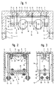
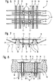
- a Load island 6 according to FIGS. 6 and 7 consists of anchors 7 with External thread and head 7.1, from anchors 8 with internal thread and head 8.1, from a steel plate 9 and from one 6 and 7 armoring basket 10 explained in more detail two anchors 7 with external thread and head 7.1 hold one Bracket 11 with a bearing 12 and a spring element 13 on which a roller bar 14 of a roller frame 15 rests.
- roller carrier 16 On the roller beam 14 is a roller carrier 16 with rope pulleys 17 arranged.
- the anchor 8 with internal thread and head 8.1 are associated with mounting rods 18, the assembly and securing the roller stand 15 serve.
- FIG. 8 Another The variant of the load island 6 is shown in FIG. 8 shown.
- the bracket 11 is by means of first nuts 19 on the anchors 7 with external thread fixed. The nuts 19 are tightened until first disc springs 19.1 are pushed completely through. First lock nuts 20 secure the first nuts 19. In addition, the bracket 11 is by means of a pinhole 21 used splints secured. First screws 22 connect the bearing 12 to the bracket 11.
- the roller beam 14 has a foot 23 covering the spring element 13 on. Loosely tightened locking screws 24 hold it Spring element 13 between the foot 23 and the bearing 12 firmly.
- Assembly rods 18 are screwed to the anchors with an internal thread 8 and secured with third nuts 25.
- the third nuts 25 are tightened until the second disc springs 25.1 be pushed through completely.
- At the bottom of the Mounting rods 18 is one of the roller bar 14 spaced securing bracket 26 arranged by second nuts 27 and second lock nuts 28 secured becomes.
- the load island 6 consists of anchors 7 with External thread and head 7.1, from anchors 8 with internal thread and head 8.1, from a steel plate 9 and from a Reinforcement basket 10 with one of reinforcement elements existing reinforcement mesh.
- the steel plate 9 serves as Spacers for the anchors 7, 8 and as a contact surface for Brackets and washers.
- an armored Ceiling plate made of concrete in the upper area a pressure zone and a train zone in the lower area.
- First Reinforcing elements 29 spaced the top of the Ceiling plate 5 existing pressure zone reinforcement from the bottom 5 existing tension zone reinforcement in the ceiling slab. in the Tension zone area spacing third reinforcement elements 30 the first reinforcing elements 29.
- the anchor 7 with External thread and head 7.1 and the anchor 8 with Internal thread and head 8.1 extend into the Pressure zone area of the ceiling plate 5.
- the heads 7.1, 8.1 the anchors 7, 8 engage positively behind the second Reinforcing elements 31 as a safeguard against being pulled out the ceiling plate 5.
- the outgoing from the anchors 7, 8 Force is generated by means of the first reinforcement elements 29, by means of the second reinforcement elements 31 and fourth Reinforcing elements 32 introduced into the pressure zone area.
- a rod-shaped base is called, the first reinforcing element 29 from the steel plate 9 spaced.
- Reinforcing elements 29, 30, 31, 32, 33 and Anchors 7, 8 are like the rest before concreting Reinforcement of the ceiling slab 5 tied with wire. Deviating from this variant, the Reinforcing elements 29, 30, 31, 32, 33 mutually and with the anchors 7, 8 are welded. This will make the form-fitting heads 7.1 and 8.1 can be dispensed with.
- the suspension cables also pose the problem of fastening the Rope ends in the shaft head. So far, the suspension of the Rope ends cross beams have been used on the one hand Roller frame and on the other rest on the shaft wall.
- the shaft head element 3 according to the invention is not only used for the suspension of the roller stand 15, but also serves with the spread over the ceiling plate 5 arranged load islands 6 of the suspension of the rope ends.
- the box-shaped described in Fig. 1 Shaft head element 3 is used for small elevator systems used. It is made in one piece from reinforced concrete manufactured. For lifting in the overhead Pressure zones become weaker and the reinforcements in the train zones below become stronger flat areas Reinforcements inserted. In addition, the above Reinforcement baskets 10 arranged without the flat Reinforcement must be changed. For small elevator systems with limited space at the end of each day Roller bar 14 a bracket 11 with bearing 12 and spring element 13 and a safety bracket 26 used. With larger ones Elevators will double each end of the roller bar 14 hung and secured.
- Fig. 8 shows a further embodiment of the Anchoring 7 and reinforcement cage 10 existing load island 6.
- Each Load island 6 has the ceiling plate 5 in the pressure zone area at least one recess 35 into which a fifth Reinforcing element 36 is inserted.
- the pressure zone reinforcement like the draft zone reinforcement are those in the load island area occurring forces designed accordingly.
- the anchor 7 penetrate arranged on the ceiling plate 5 Through holes 37 into which tubes 38 can be inserted.
- the heads 7.1 of the armature 7 engage behind the fifth Reinforcing element 36. After the assembly of the load island 6 the recess 35 poured out.
- FIG. 9 is a further embodiment of the Shaft head element 3 shown.
- the shaft head element 3 only from the ceiling plate 5, which on the shaft walls 2 placed and fastened by means of second screws 34 becomes.
- This variant mainly takes place at tubular elevator shafts or large ones Manhole cross sections application.
- Factory-made shaft head element 3 also enables factory assembly of the Roller frame 15.
- the box-shaped one also serves Manhole head element 3 as a transport container for it assembled roller frame 15.
- the roller frame 15 is the shaft head element 3 the bottom up.
- the brackets 11 are placed by means of the first nuts 19 screwed to the anchors 7 with an external thread and secured by means of the first lock nuts 20 and split pins.
- the mounting rods 18 in the anchor 8 with Internal thread screwed in and by means of the third nut 25 set.
- this will be Roller stand 15 retracted and on the third nuts 25 hung up, then mounted the safety bracket 26 and the second nuts 27 and the second lock nuts 28 turned up.
- the spring elements 13 are then inserted and the bearings 12 assembled.
Landscapes
- Engineering & Computer Science (AREA)
- Civil Engineering (AREA)
- Mechanical Engineering (AREA)
- Structural Engineering (AREA)
- Lift-Guide Devices, And Elevator Ropes And Cables (AREA)
- Heat Treatment Of Articles (AREA)
- Types And Forms Of Lifts (AREA)
- Conveying And Assembling Of Building Elements In Situ (AREA)
- Shafts, Cranks, Connecting Bars, And Related Bearings (AREA)
- Fluid-Damping Devices (AREA)
- Forging (AREA)
- Rotary Pumps (AREA)
- Superconductors And Manufacturing Methods Therefor (AREA)
Description
Es zeigen:
- Fig. 1
- ein erfindungsgemässes Schachtkopfelement mit einem Rollengerüst,
- Fig. 2
- eine Seitenansicht A des am erfindungsgemässen Schachtkopfelement aufgehängten Rollengerüstes,
- Fig. 3
- eine Frontansicht des am erfindungsgemässen Schachtkopfelement aufgehängten Rollengerüstes,
- Fig. 4
- eine Frontansicht einer Einrichtung zur Montage und Transportsicherung des Rollengerüstes,
- Fig. 5
- eine Seitenansicht der Montageeinrichtung gemäss Fig. 4,
- Fig. 6
- eine Draufsicht eines im Schachtkopfelement angeordneten Armierungskorbes,
- Fig. 7
- eine Seitenansicht des Armierungskorbes gemäss Fig. 6,
- Fig. 8
- eine Ausführungsvariante einer Lastinsel und
- Fig. 9
- eine Ausführungsvariante des erfindungsgemässen Schachtkopfelementes.
Claims (10)
- Schachtkopf für einen Aufzugsschacht (1) mit einem am Schachtkopf (1.1) angeordneten Rollengerüst (15) bestehend aus einem Rollenbalken (14) und einem Rollenträger (16) mit mindestens einer Seilrolle (17), wobei der Rollenbalken (14) in Verbindung mit dem Schachtkopf (1.1) steht,
dadurch gekennzeichnet,dass der Schachtkopf (1.1) ein Schachtkopfelement (3) mit einer mit Mitteln (6, 11, 12, 13) zur Aufhängung des Rollengerüstes (15) versehenen Deckenplatte (5) aufweist, welche den Aufzugsschacht (1) nach oben hin abschliesst. - Schachtkopf nach Anspruch 1,
dadurch gekennzeichnet,dass das Schachtkopfelement (3) mindestens eine aus Ankern (7, 8) und Armierungskorb (10) bestehende Lastinsel (6) zur Lastaufnahme aufweist. - Schachtkopf nach Anspruch 2,
dadurch gekennzeichnet,dass der Armierungskorb (10) Armierungselemente (29, 31, 32, 36) aufweist, die die auf die Anker (7, 8) ausgeübte Kraft in die Druckzone der Deckenplatte (5) des Schachtkopfelementes (3) einleiten. - Schachtkopf nach den Ansprüchen 2 und 3,
dadurch gekennzeichnet,dass die Anker (7, 8) an den in der Druckzone der Deckenplatte (5) liegenden Enden Köpfe (7.1, 8.1) aufweisen, die die Armierungselemente (31, 36) hintergreifen. - Schachtkopf nach den Ansprüchen 3 und 4,
dadurch gekennzeichnet,dass die Anker (7, 8) fest mit den Armierungselementen (31, 36) verbunden sind. - Schachtkopf nach Anspruch 2,
dadurch gekennzeichnet,dass die Lastinsel (6) eine an der Deckenplattenunterseite angeordnete Stahlplatte (9) als Abstandshalter für die Anker (7, 8) aufweist. - Schachtkopf nach den Ansprüchen 2 bis 6,
dadurch gekennzeichnet,dass mindestens eine Lastinsel (6) zur Aufhängung eines Bügels (11) mit einem Lager (12) und einem Federelement (13) vorgesehen ist, an dem der Rollenbalken (14) aufliegt. - Schachtkopf nach den Ansprüchen 2 bis 6,
dadurch gekennzeichnet,dass mindestens eine Lastinsel (6) zur Aufhängung mindestens einer Montagestange (18) mit einem Sicherungsbügel (26) vorgesehen ist, die der Montage und der Sicherung des Rollengerüstes (15) dienen. - Schachtkopf nach den Ansprüchen 2 bis 6,
dadurch gekennzeichnet,dass mindestens eine Lastinsel (6) zur Aufhängung eines Seilendes vorgesehen ist. - Schachtkopf nach einem der vorangehenden Ansprüche,
dadurch gekennzeichnet,dass das Schachtkopfelement (3) mit den Lastinseln (6) fabrikseitig vorgefertigt ist unddass das Rollengerüst (15) fabrikseitig an der Deckenplatte (5) des Schachtkopfelementes (5) vormontiert ist.
Priority Applications (6)
| Application Number | Priority Date | Filing Date | Title |
|---|---|---|---|
| AT94106824T ATE183480T1 (de) | 1994-05-02 | 1994-05-02 | Schachtkopf für einen aufzugsschacht |
| EP94106824A EP0680919B1 (de) | 1994-05-02 | 1994-05-02 | Schachtkopf für einen Aufzugsschacht |
| DE59408642T DE59408642D1 (de) | 1994-05-02 | 1994-05-02 | Schachtkopf für einen Aufzugsschacht |
| CZ951029A CZ282540B6 (cs) | 1994-05-02 | 1995-04-21 | Horní část výtahové šachty |
| PL95308324A PL178882B1 (pl) | 1994-05-02 | 1995-04-24 | Głowica szybu wyciągowego |
| HU9501265A HU217901B (hu) | 1994-05-02 | 1995-05-02 | Aknafej liftakna részére |
Applications Claiming Priority (1)
| Application Number | Priority Date | Filing Date | Title |
|---|---|---|---|
| EP94106824A EP0680919B1 (de) | 1994-05-02 | 1994-05-02 | Schachtkopf für einen Aufzugsschacht |
Publications (2)
| Publication Number | Publication Date |
|---|---|
| EP0680919A1 EP0680919A1 (de) | 1995-11-08 |
| EP0680919B1 true EP0680919B1 (de) | 1999-08-18 |
Family
ID=8215905
Family Applications (1)
| Application Number | Title | Priority Date | Filing Date |
|---|---|---|---|
| EP94106824A Expired - Lifetime EP0680919B1 (de) | 1994-05-02 | 1994-05-02 | Schachtkopf für einen Aufzugsschacht |
Country Status (6)
| Country | Link |
|---|---|
| EP (1) | EP0680919B1 (de) |
| AT (1) | ATE183480T1 (de) |
| CZ (1) | CZ282540B6 (de) |
| DE (1) | DE59408642D1 (de) |
| HU (1) | HU217901B (de) |
| PL (1) | PL178882B1 (de) |
Family Cites Families (2)
| Publication number | Priority date | Publication date | Assignee | Title |
|---|---|---|---|---|
| CH384168A (de) * | 1960-02-26 | 1964-11-15 | A K Gebauer & Cie | Tragelement für Aufzugsantrieb |
| DE2441882C3 (de) * | 1974-08-31 | 1980-05-14 | Continental Gummi-Werke Ag, 3000 Hannover | Lager für Aufzüge |
-
1994
- 1994-05-02 EP EP94106824A patent/EP0680919B1/de not_active Expired - Lifetime
- 1994-05-02 AT AT94106824T patent/ATE183480T1/de active
- 1994-05-02 DE DE59408642T patent/DE59408642D1/de not_active Expired - Fee Related
-
1995
- 1995-04-21 CZ CZ951029A patent/CZ282540B6/cs not_active IP Right Cessation
- 1995-04-24 PL PL95308324A patent/PL178882B1/pl unknown
- 1995-05-02 HU HU9501265A patent/HU217901B/hu unknown
Also Published As
| Publication number | Publication date |
|---|---|
| DE59408642D1 (de) | 1999-09-23 |
| CZ102995A3 (en) | 1996-03-13 |
| PL178882B1 (pl) | 2000-06-30 |
| HU217901B (hu) | 2000-05-28 |
| EP0680919A1 (de) | 1995-11-08 |
| CZ282540B6 (cs) | 1997-08-13 |
| HUT73576A (en) | 1996-08-28 |
| ATE183480T1 (de) | 1999-09-15 |
| HU9501265D0 (en) | 1995-06-28 |
| PL308324A1 (en) | 1995-11-13 |
Similar Documents
| Publication | Publication Date | Title |
|---|---|---|
| WO2022233803A1 (de) | Topmodul und verfahren zum abschliessen eines aufzugschachts einer aufzuganlage | |
| DE102006011336A1 (de) | Bauelement zur Wärmedämmung | |
| DE102017114090B4 (de) | Verfahren zur Errichtung eines Gebäudes | |
| EP1303455A1 (de) | Erdbebensicheres auflager für fahrtreppe oder fahrsteig | |
| EP0318712A1 (de) | Verbindungsvorrichtung zum Anschliessen einer Betondecke an eine Stütze sowie Bauwerk | |
| EP0627307B1 (de) | Unterbau für eine Rollenrotations-Druckmaschine und Verfahren zur Installation einer Rollenrotations-Druckmaschine auf einem solchen Unterbau | |
| EP2378030A2 (de) | Schalungssystem | |
| EP0187326B1 (de) | Manipulator und Verfahren zur Bewegung von auf einer Unterlage befindlichen Teilen in ihre Einbauposition | |
| EP0680919A1 (de) | Schachtkopf für einen Aufzugsschacht | |
| EP2069581B2 (de) | Stahlbetonkonstruktion für ein gebäude | |
| DE3815911C2 (de) | ||
| AT392312B (de) | Verstaerkungskonstruktion | |
| EP0577004A1 (de) | Verankerungsvorrichtung | |
| DE20316406U1 (de) | Bauelement zur insbesonderen nachträglichen beabstandeten Befestigung von Bauteilen an Gebäudeteilen | |
| DE1759316A1 (de) | Verfahren zum Bau eines mehrstoeckigen Gebaeudes und Vorrichtung zur Durchfuehrung des Verfahrens | |
| DE102024101215A1 (de) | Bauweise zum Anheben oder Absenken einer Hängekonstruktion | |
| WO2025036738A1 (de) | Verfahren zur installation einer aufzuganlage | |
| DE19700686A1 (de) | Konsolanker | |
| EP3611310B1 (de) | Brüstungsanker | |
| WO2019001889A1 (de) | Aufzugsanlage | |
| EP1785386A1 (de) | Verfahren zum Aufbau einer Aufzuganlage und Aufzugsanlage hierfür | |
| DE29712809U1 (de) | Anordnung zur Abstützung des Balkongeländers an der Balkondecke | |
| WO2000005461A1 (de) | Stahlbetonplatte und schubbewehrungselement zur schubbewehrung von stahlbetonplatten | |
| DE102023128731A1 (de) | System zur Montage eines Balkons an einem Gebäude | |
| DE202024002501U1 (de) | Stützvorrichtung mit Auffangsicherung |
Legal Events
| Date | Code | Title | Description |
|---|---|---|---|
| PUAI | Public reference made under article 153(3) epc to a published international application that has entered the european phase |
Free format text: ORIGINAL CODE: 0009012 |
|
| AK | Designated contracting states |
Kind code of ref document: A1 Designated state(s): AT CH DE FR GB LI |
|
| RBV | Designated contracting states (corrected) |
Designated state(s): AT CH DE FR GB LI |
|
| 17P | Request for examination filed |
Effective date: 19960417 |
|
| GRAG | Despatch of communication of intention to grant |
Free format text: ORIGINAL CODE: EPIDOS AGRA |
|
| 17Q | First examination report despatched |
Effective date: 19981012 |
|
| GRAG | Despatch of communication of intention to grant |
Free format text: ORIGINAL CODE: EPIDOS AGRA |
|
| GRAH | Despatch of communication of intention to grant a patent |
Free format text: ORIGINAL CODE: EPIDOS IGRA |
|
| GRAH | Despatch of communication of intention to grant a patent |
Free format text: ORIGINAL CODE: EPIDOS IGRA |
|
| GRAA | (expected) grant |
Free format text: ORIGINAL CODE: 0009210 |
|
| AK | Designated contracting states |
Kind code of ref document: B1 Designated state(s): AT CH DE FR GB LI |
|
| PG25 | Lapsed in a contracting state [announced via postgrant information from national office to epo] |
Ref country code: GB Free format text: LAPSE BECAUSE OF FAILURE TO SUBMIT A TRANSLATION OF THE DESCRIPTION OR TO PAY THE FEE WITHIN THE PRESCRIBED TIME-LIMIT Effective date: 19990818 |
|
| REF | Corresponds to: |
Ref document number: 183480 Country of ref document: AT Date of ref document: 19990915 Kind code of ref document: T |
|
| REG | Reference to a national code |
Ref country code: CH Ref legal event code: EP |
|
| REF | Corresponds to: |
Ref document number: 59408642 Country of ref document: DE Date of ref document: 19990923 |
|
| ET | Fr: translation filed | ||
| GBV | Gb: ep patent (uk) treated as always having been void in accordance with gb section 77(7)/1977 [no translation filed] |
Effective date: 19990818 |
|
| PG25 | Lapsed in a contracting state [announced via postgrant information from national office to epo] |
Ref country code: AT Free format text: LAPSE BECAUSE OF NON-PAYMENT OF DUE FEES Effective date: 20000502 |
|
| PLBE | No opposition filed within time limit |
Free format text: ORIGINAL CODE: 0009261 |
|
| STAA | Information on the status of an ep patent application or granted ep patent |
Free format text: STATUS: NO OPPOSITION FILED WITHIN TIME LIMIT |
|
| 26N | No opposition filed | ||
| PGFP | Annual fee paid to national office [announced via postgrant information from national office to epo] |
Ref country code: DE Payment date: 20080523 Year of fee payment: 15 |
|
| PGFP | Annual fee paid to national office [announced via postgrant information from national office to epo] |
Ref country code: CH Payment date: 20080815 Year of fee payment: 15 |
|
| REG | Reference to a national code |
Ref country code: CH Ref legal event code: PL |
|
| PG25 | Lapsed in a contracting state [announced via postgrant information from national office to epo] |
Ref country code: LI Free format text: LAPSE BECAUSE OF NON-PAYMENT OF DUE FEES Effective date: 20090531 Ref country code: CH Free format text: LAPSE BECAUSE OF NON-PAYMENT OF DUE FEES Effective date: 20090531 |
|
| REG | Reference to a national code |
Ref country code: FR Ref legal event code: ST Effective date: 20100129 |
|
| PG25 | Lapsed in a contracting state [announced via postgrant information from national office to epo] |
Ref country code: FR Free format text: LAPSE BECAUSE OF NON-PAYMENT OF DUE FEES Effective date: 20090602 |
|
| PGFP | Annual fee paid to national office [announced via postgrant information from national office to epo] |
Ref country code: FR Payment date: 20080425 Year of fee payment: 15 |
|
| PG25 | Lapsed in a contracting state [announced via postgrant information from national office to epo] |
Ref country code: DE Free format text: LAPSE BECAUSE OF NON-PAYMENT OF DUE FEES Effective date: 20091201 |