EP0680908B1 - Vorrichtung zur Anpassung des Unterdruckes in einem Saugbandzuführtisch eines Bogenanlegers - Google Patents
Vorrichtung zur Anpassung des Unterdruckes in einem Saugbandzuführtisch eines Bogenanlegers Download PDFInfo
- Publication number
- EP0680908B1 EP0680908B1 EP95105620A EP95105620A EP0680908B1 EP 0680908 B1 EP0680908 B1 EP 0680908B1 EP 95105620 A EP95105620 A EP 95105620A EP 95105620 A EP95105620 A EP 95105620A EP 0680908 B1 EP0680908 B1 EP 0680908B1
- Authority
- EP
- European Patent Office
- Prior art keywords
- suction
- shut
- sheet
- vacuum
- connection piece
- Prior art date
- Legal status (The legal status is an assumption and is not a legal conclusion. Google has not performed a legal analysis and makes no representation as to the accuracy of the status listed.)
- Expired - Lifetime
Links
- 230000032258 transport Effects 0.000 claims 1
- 238000009423 ventilation Methods 0.000 description 8
- 230000000694 effects Effects 0.000 description 3
- 101000952234 Homo sapiens Sphingolipid delta(4)-desaturase DES1 Proteins 0.000 description 2
- 102100037416 Sphingolipid delta(4)-desaturase DES1 Human genes 0.000 description 2
- 230000001737 promoting effect Effects 0.000 description 2
- 230000006978 adaptation Effects 0.000 description 1
- 238000013459 approach Methods 0.000 description 1
- 230000003292 diminished effect Effects 0.000 description 1
- 238000005516 engineering process Methods 0.000 description 1
- 239000002184 metal Substances 0.000 description 1
- 238000007789 sealing Methods 0.000 description 1
- 239000002699 waste material Substances 0.000 description 1
Images



Classifications
-
- B—PERFORMING OPERATIONS; TRANSPORTING
- B65—CONVEYING; PACKING; STORING; HANDLING THIN OR FILAMENTARY MATERIAL
- B65H—HANDLING THIN OR FILAMENTARY MATERIAL, e.g. SHEETS, WEBS, CABLES
- B65H11/00—Feed tables
- B65H11/002—Feed tables incorporating transport belts
- B65H11/005—Suction belts
-
- B—PERFORMING OPERATIONS; TRANSPORTING
- B65—CONVEYING; PACKING; STORING; HANDLING THIN OR FILAMENTARY MATERIAL
- B65H—HANDLING THIN OR FILAMENTARY MATERIAL, e.g. SHEETS, WEBS, CABLES
- B65H5/00—Feeding articles separated from piles; Feeding articles to machines
- B65H5/24—Feeding articles in overlapping streams, i.e. by separation of articles from a pile
-
- B—PERFORMING OPERATIONS; TRANSPORTING
- B65—CONVEYING; PACKING; STORING; HANDLING THIN OR FILAMENTARY MATERIAL
- B65H—HANDLING THIN OR FILAMENTARY MATERIAL, e.g. SHEETS, WEBS, CABLES
- B65H2406/00—Means using fluid
- B65H2406/30—Suction means
- B65H2406/32—Suction belts
- B65H2406/321—Suction belts integral in feed table
-
- B—PERFORMING OPERATIONS; TRANSPORTING
- B65—CONVEYING; PACKING; STORING; HANDLING THIN OR FILAMENTARY MATERIAL
- B65H—HANDLING THIN OR FILAMENTARY MATERIAL, e.g. SHEETS, WEBS, CABLES
- B65H2801/00—Application field
- B65H2801/03—Image reproduction devices
- B65H2801/21—Industrial-size printers, e.g. rotary printing press
Definitions
- the invention relates to a device for adaptation of the negative pressure in a suction belt feed table Sheet feeder changing during sheet feeding Operating conditions, with at least one endless, rotating drivable conveyor belt, which with suction openings is provided with a side alignment device for lateral alignment of the foremost bow of each scaled arc stream and with one below one Conveyor plane arranged suction box, which, in Seen sheet conveying direction, divided into several suction chambers is the pressurizable are.
- the Japanese Utility model disclosure Hei 4-91953 is a device known to switch the suction effect.
- An articulated stored actuating cylinder rotates one using a lever Rotation axis on which a flap provided with two sealing surfaces is attached.
- the flap can either connect to atmospheric pressure level or a connection with a Vacuum source can be realized.
- This device is disadvantageous in that a complete 90 ° swivel movement of the flap got to. This has the consequence that, due to the inertia of the mass to be pivoted, a certain pivoting time is required. So there is none during the pan time clearly defined switching state. At high Sheet conveying speeds is therefore an abrupt, atmospheric ventilation of a suction chamber not possible.
- the promotion of a shingled stream of arcs on the A feeder table of a sheet-fed rotary printing press can be divided into three phases.
- the first phase leaves are characterized in that the first sheet from the separating device to the Suction belt is pushed, as little slip as possible on the perforated conveyor belt to be sucked.
- the suction power is fundamental to machine operation reduced by the fact that only a certain area of the Conveyor belt is covered by the first sheet and thus a lot of incorrect air is sucked in, the suction effect is limited.
- the first phase is particularly critical, though with a small scale length both with and without Driving rollers on the belt drive roller at the top of the Feeding table is being worked.
- the third phase of the promotion of a shingled stream of arcs concerns the promotion of the last sheet of the scaled Arc current.
- This arch is on along its entire length the conveyor belt is sucked and is therefore much stronger fixed on the conveyor belt as the partially overlapping arc of the shingled stream. With this If the individual sheets overlap, the sheets only with a fraction of their area with the conveyor belt in Contact, resulting in less suction are subject.
- the last bow remains with his Transport against the front brands in the feed table exposed to negative pressure, on the one hand the Front edge of the last sheet on the front marks indented and on the other hand not the lateral alignment be insignificantly disabled.
- the invention has for its object the negative pressure in Feed table of a sheet feeder of the respective operating phase adapt.
- the pivotable Shut-off element in the plane of a boundary of the suction nozzle is arranged. It does not form any in a passive position Flow resistance in the suction nozzle and allows a smaller one Dimensioning of the suction air source.
- pivotable shut-off element eccentrically on one Swivel axis attached which is characterized by the eccentric Storage, based on the swivel axis, resulting shorter Section of the pivotable shut-off element closes or opens a ventilation opening in a boundary wall of the suction nozzle.
- the eccentric bearing resulting longer section of the shut-off element interrupts the connection of a suction chamber to the common suction nozzle.
- the suction chambers are on trusses below the conveyor level of the arc stream attached.
- the trusses in turn are penetrated by breakthroughs outside the Swivel range of the shut-off element are. This gives themselves that the suction chambers, their respective suction channels through the breakthroughs permanently with the common suction nozzle connected, consequently permanently subjected to vacuum are and none by the pivoting movement of the shut-off element Experience influence.
- is located at the Trusses each have a suction box into which the front and open rear suction chambers.
- the actuation of the pivotable shut-off element is both with a a pressurized actuating cylinder as well electromagnetically realizable.
- the invention is based on a drawing explained in detail.
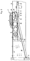
- FIG. 1 shows that a conveyor level 5 to supply one sheet-fed rotary printing press Has suction chambers I, II, III, each of curly Brackets 1, 2, 3 are overlapped.
- the suction chamber I is located directly adjoining a belt drive roller 8, behind a pivotable stop 6 one Feeder stack 4.
- the front suction chamber I extends to to a first web 12 below the conveyor level 5.
- a middle suction chamber II which extends up to a pull roll 10 of a side aligner extends.
- a rear one Suction chamber III formed by a sheet metal part of the middle suction chamber II is separated. Behind the Conveying level 5, the front marks 11 are arranged on which the individual sheets are aligned.
- the housing in which the suction chambers I, II, III are formed are attached to trusses 14 and 15, which are transverse extend to the conveying direction of the arc stream.
- the two Trusses 14 and 15 serve as storage points for the ends a pivot axis 20 on which a shut-off element 17 is attached.
- the shut-off element 17 is by means of a Screw 21 added to the pivot axis 20.
- the Traverse 15 receives an abutment 22 in which Actuator 18 is articulated at the end a control fork 19 is attached, the retraction and extension causes rotation of the pivot axis 20.
- a rear suction box 24, in the a suction channel of the suction chamber I opens.
- Both trusses 14 and 15 are provided with openings 16, whereby the Suction boxes 23 and 24 with the common suction nozzle 38 in Connect.
- the suction nozzle 38 is of the two Trusses 14 and 15 limited, as well as on its underside completed by a sheet 29 on which a strip-shaped Seal 26 is attached. This serves as a stop for an end portion of the shut-off element 17 while above of the shut-off element 17, a further seal 25 is provided to which the other end of the shut-off element 17th strikes.
- Figure 2 shows a cross section through the feed table in the Operating phase promotion of the 1st sheet.
- the housing is accommodated in the center in the conveying plane 5, in which the suction chambers I, II, III are formed and around which rotates the endless conveyor belt 9.
- the Funding level 5 is limited by feeder side parts 31. Between the side parts 31 and the suction chamber housing extend table plates.
- the cross member 15 extends between the investor side parts 31; that's about her Abutment 22 of the actuator 18 added.
- the Control fork 19 stands with the pivot axis 20 via a lever in connection.
- the pivot axis 20 divides the pivotable Shut-off element 17 in this embodiment approximately in 2: 1 ratio.
- the eccentric arrangement of the Shut-off element 17, based on the pivot axis 20, causes a division of the shut-off element 17.
- the shorter side gives in the representation shown in Figure 2 an atmospheric Ventilation opening of the middle suction chamber II free; the middle suction chamber II does not suck. Accordingly becomes eccentric through the elongated section of the stored shut-off element 17 the connection of the middle Suction chamber II interrupted with the suction nozzle 38. Since the Openings 16 in the areas of the cross members 14 and 15, that limit the suction port 38, are included outside the swivel range of the shut-off element 17 the vacuum is in suction chambers I and III regardless of the position of the shut-off element 17 continues on. The shut-off element 17 takes the in this operating phase Position 36 a.
- the suction port 38 is in the embodiment shown from several sheets 27, 28 and 29 To form suction nozzle 38 tubular, with a deviating geometry of the shut-off element 17 would result.
- the Using a rectangular tube would be also conceivable.
- the suction air in suction chamber I flows into the rear suction box 24 a.
- the openings 16 in the cross member 15 flows the suction air into the suction port 38, regardless of the working position of the shut-off element 17th
- the suction air flow acting on the middle suction chamber II is with the shut-off element 17 down (see Figure 4) sucked through the suction port 38.
- This in Suction chamber III pending vacuum is above the front Suction box 23 and the openings 16 in the cross member 14 with the suction nozzle 38 - regardless of the working position of the shut-off element 17 -.
- FIG. 4 an illustration of the section IV-IV from FIG. 3 is the working position 37 of the shut-off element 17th reproduced.
- a fully developed arc current see Fig. 3
- the shut-off element 17 down pivoted, whereby the vacuum prevailing in the suction nozzle 38, also in suction chamber II below the scaled Arc stream promoting conveyor belt 9 is present.
- Working position 37 closes the rear section of the eccentrically mounted shut-off element 17 the atmospheric Ventilation opening between pivot axis 20 and Seal 25 on the face plate 28.
- the working position 36 of the Shut-off element 17 enables the ventilation of the Suction chamber II, while the suction chambers I and III, analogous to Promotion of the 1st sheet 32 with the suction port 38 in Stay connected.
Landscapes
- Engineering & Computer Science (AREA)
- Mechanical Engineering (AREA)
- Delivering By Means Of Belts And Rollers (AREA)
- Feeding Of Articles By Means Other Than Belts Or Rollers (AREA)
Description
- Fig. 1
- die Unterdruckverhältnisse in den Saugkammern beim Maschinenanlauf (Förderung des 1. Bogens),
- Fig. 2
- einen Querschnitt durch den Zuführtisch mit atmosphärischer Belüftung der mittleren Saugkammer (Förderung des 1. Bogens),
- Fig. 3
- die Unterdruckverteilung der Förderung eines vollausgebildeten Schuppenstromes im Längsschnitt durch den Zuführtisch,
- Fig. 4
- die zu Figur 3 korrespondierende Arbeitsposition des verschwenkbaren Absperrelementes im Querschnitt durch die Förderebene des Bogenstromes,
- Fig. 5
- die Unterdruckverteilung der Förderung des letzten Bogens und
- Fig. 6
- die atmosphärische Belüftung eines Saugkanales zur Herabsetzung der Saugluftbeaufschlagung eines letzten Bogens.
- 1
- Saugkammer I
- 2
- Saugkammer II
- 3
- Saugkammer III
- 4
- Anlegerstapel
- 5
- Förderebene
- 6
- schwenkbarer Anschlag
- 7
- Taktrolle
- 8
- Bänderantriebswalze
- 9
- Transportband
- 10
- Ziehrolle
- 11
- Vordermarke
- 12
- Steg
- 13
- Umlenkwalze
- 14
- Traverse
- 15
- Traverse
- 16
- Durchbrechung
- 17
- Absperrelement
- 18
- Betätigungsorgan
- 19
- Steuergabel
- 20
- Schwenkachse
- 21
- Verschraubung
- 22
- Widerlager
- 23
- Saugkasten vorne
- 24
- Saugkasten hinten
- 25
- Abdichtung
- 26
- Abdichtung
- 27
- Blech
- 28
- Stirnblech
- 29
- Blech
- 31
- Anlegerseitenteil
- 32
- 1. Bogen
- 33
- ausgebildeter Bogenstrom
- 35
- Letzter Bogen
- 36
- obere Arbeitsposition
- 37
- untere Arbeitsposition
- 38
- Saugstutzen
- 39
- maximale Bogenlänge
Claims (11)
- Vorrichtung zur Anpassung des Unterdruckes in einem Saugbandzuführtisch eines Bogenanlegers an sich während der Bogenförderung ändernde Betriebsbedingungen,dadurch gekennzeichnet,mit mindestens einem endlosen, umlaufend antreibbaren Förderband (9), welches mit Saugöffnungen versehen ist, und einen Bogen an vorgesehene Vordermarken (11) transportiert,mit einer Seitenausrichtvorrichtung zum seitlichen Ausrichten des jeweils vordersten Bogens eines geschuppten Bogenstromes,mit einem unterhalb einer Förderebene angeordneten Saugkasten, der in Bogenförderrichtung gesehen, in mehrere Saugkammern (I, II, III) unterteilt ist, die unterdruckbeaufschlagbar sind,daß allen Saugkammern (I, II, III) ein gemeinsamer Saugstutzen (38) zugeordnet ist unddaß die Saugkammer (II) mittels eines Absperrelementes (17) wahlweise mit dem gemeinsamen Saugstutzen (38) oder einer Belüftungsöffnung schaltbar ist.
- Vorrichtung gemäß Anspruch 1, dadurch gekennzeichnet,daß das verschwenkbare Absperrelement (17) in der Ebene einer Begrenzung (29) des Saugstutzens (38) angeordnet ist.
- Vorrichtung gemäß Anspruch 1,
dadurch gekennzeichnet,daß das verschwenkbare Absperrelement (17) exzentrisch an einer Schwenkachse (20) befestigt ist. - Vorrichtung gemäß Anspruch 3,
dadurch gekennzeichnet,daß ein, bezogen auf die Schwenkachse (20), kürzerer Abschnitt des verschwenkbaren Absperrelementes (17) eine Belüftungsöffnung in einer Begrenzung (29) verschließt oder freigibt. - Vorrichtung gemäß Anspruch 3,
dadurch gekennzeichnet,daß ein, bezogen auf die Schwenkachse (20), längerer Abschnitt des verschwenkbaren Absperrelementes (17) die Verbindung der Saugkammer (2)zum Saugstutzen (38) unterbricht. - Vorrichtung gemäß Anspruch 1,
dadurch gekennzeichnet,daß die Saugkammern (1, 2, 3) auf Traversen (14, 15) unterhalb der Förderebene (5) befestigt sind. - Vorrichtung gemäß Anspruch 6,
dadurch gekennzeichnet,daß die Traversen (14, 15) jeweils von Durchbrechungen (16) durchsetzt sind, die außerhalb des Schwenkbereiches des Absperrelementes (17) liegen. - Vorrichtung gemäß Anspruch 6,
dadurch gekennzeichnet,daß die Traversen (14, 15) jeweils einen Saugkasten (23, 24) aufnehmen. - Vorrichtung gemäß einem oder mehreren der vorhergehenden Ansprüche,
dadurch gekennzeichnet,daß die Saugkammern (1, 3) über die Durchbrechungen (16) mit dem Saugstutzen (38) permanent in Verbindung stehen. - Vorrichtung gemäß Anspruch 1,
dadurch gekennzeichnet,daß das verschwenkbare Absperrelement (17) ferngesteuert betätigbar ist. - Vorrichtung gemäß Anspruch 6,
dadurch gekennzeichnet,daß die Traversen (14, 15) Begrenzungen des Saugstutzens (38) bilden.
Applications Claiming Priority (2)
| Application Number | Priority Date | Filing Date | Title |
|---|---|---|---|
| DE4416286 | 1994-05-07 | ||
| DE4416286A DE4416286C2 (de) | 1994-05-07 | 1994-05-07 | Vorrichtung zur Anpassung des Unterdruckes in einem Saugbandzuführtisch eines Bogenanlegers |
Publications (2)
| Publication Number | Publication Date |
|---|---|
| EP0680908A1 EP0680908A1 (de) | 1995-11-08 |
| EP0680908B1 true EP0680908B1 (de) | 1999-03-24 |
Family
ID=6517649
Family Applications (1)
| Application Number | Title | Priority Date | Filing Date |
|---|---|---|---|
| EP95105620A Expired - Lifetime EP0680908B1 (de) | 1994-05-07 | 1995-04-13 | Vorrichtung zur Anpassung des Unterdruckes in einem Saugbandzuführtisch eines Bogenanlegers |
Country Status (4)
| Country | Link |
|---|---|
| US (1) | US5697606A (de) |
| EP (1) | EP0680908B1 (de) |
| JP (1) | JP3522386B2 (de) |
| DE (2) | DE4416286C2 (de) |
Families Citing this family (24)
| Publication number | Priority date | Publication date | Assignee | Title |
|---|---|---|---|---|
| DE19616714A1 (de) * | 1996-04-26 | 1997-11-06 | Heidelberger Druckmasch Ag | Vorrichtung zum Fördern eines insbesondere geschuppten Stroms von Bogen zu einer bogenverarbeitenden Maschine |
| DE19618870A1 (de) * | 1996-05-10 | 1997-11-13 | Heidelberger Druckmasch Ag | Vorrichtung zum Fördern eines insbesondere geschuppten Stroms von Bogen zu einer bogenverarbeitenden Maschine |
| AU5310598A (en) * | 1996-12-20 | 1998-07-17 | Olsen Arne | Label stacker for a rotary machine/apparatus |
| DE19724731A1 (de) * | 1997-06-12 | 1998-12-17 | Roland Man Druckmasch | Anlegetisch |
| US6311831B1 (en) | 1998-09-10 | 2001-11-06 | Polytype America Corporation | Tube loading system |
| US6161677A (en) * | 1998-09-10 | 2000-12-19 | Polytype America Corporation | Tube loading system |
| US6243120B1 (en) * | 1999-04-08 | 2001-06-05 | Gerber Scientific Products, Inc. | Replaceable donor sheet assembly with memory for use with a thermal printer |
| DE29910850U1 (de) | 1999-06-25 | 2000-11-23 | Voith Sulzer Papiertechnik Patent GmbH, 89522 Heidenheim | Unterdruck-Fördereinrichtung |
| DE19947554C2 (de) * | 1999-10-02 | 2003-11-27 | Roland Man Druckmasch | Anlegetisch |
| US6443444B1 (en) * | 1999-10-04 | 2002-09-03 | Lockhead Martin Corporation | Singulation mechanism |
| US6481565B1 (en) * | 2000-09-26 | 2002-11-19 | Bernard J. Sherwood | Conveyor system with pneumatic transfer |
| US6575450B2 (en) | 2001-01-30 | 2003-06-10 | Lockheed Martin Corporation | Singulation mechanism |
| DE10213705C5 (de) | 2001-04-26 | 2017-01-05 | Heidelberger Druckmaschinen Ag | Vorrichtung zum Fördern eines Bogenstroms von einem Bogenstapel zu einer bogenverarbeitenden Maschine |
| US20040025466A1 (en) * | 2002-08-06 | 2004-02-12 | Marley Cooling Technologies, Inc. | Modular frame method and apparatus |
| JP4571812B2 (ja) | 2003-02-24 | 2010-10-27 | ハイデルベルガー ドルツクマシーネン アクチエンゲゼルシヤフト | シート搬送装置 |
| US7118103B2 (en) * | 2003-04-14 | 2006-10-10 | Heidelberger Druckmaschinen Ag | Device for conveying sheets through a printing machine |
| DE102004015335A1 (de) | 2004-03-30 | 2005-10-20 | Koenig & Bauer Ag | Vorrichtung zum Zuführen eines geschuppten Bogenstromes |
| US20060181011A1 (en) * | 2004-09-24 | 2006-08-17 | Heidelberger Druckmaschinen Ag | Transport belt |
| GB0511299D0 (en) * | 2005-06-03 | 2005-07-13 | Scan Coin Ind Ab | Coin conveying apparatus |
| JP2008080526A (ja) * | 2006-09-26 | 2008-04-10 | Brother Ind Ltd | 液体噴射装置 |
| US20090057998A1 (en) * | 2007-08-31 | 2009-03-05 | Pitney Bowes Inc. | Apparatus and Method for Printing And/Or Electronically Scanning Dual Face Surfaces of a Sheet/Mailpiece |
| US20120157279A1 (en) * | 2010-12-20 | 2012-06-21 | Uwe Schneider | Process and Apparatus for Joining Flexible Components |
| CN102602722B (zh) * | 2011-01-19 | 2015-10-28 | 海德堡印刷机械股份公司 | 吸带台 |
| JP5179610B2 (ja) * | 2011-03-03 | 2013-04-10 | 富士フイルム株式会社 | 用紙搬送装置及びインクジェット記録装置 |
Family Cites Families (12)
| Publication number | Priority date | Publication date | Assignee | Title |
|---|---|---|---|---|
| SU48409A1 (ru) * | 1935-08-27 | 1936-08-31 | Г.П. Дворецкий | Способ гор чего ремонта металлургических печей |
| DE1976230U (de) * | 1967-11-02 | 1968-01-04 | Albert Schnellpressen | Bogenfoerdervorrichtung am anlegetisch von druckmaschinen. |
| US3715115A (en) * | 1971-03-15 | 1973-02-06 | Harris Intertype Corp | Sheet feeding apparatus |
| JPS52159473U (de) * | 1976-05-28 | 1977-12-03 | ||
| DE2707170C2 (de) * | 1977-02-18 | 1982-07-15 | Siemens AG, 1000 Berlin und 8000 München | Pneumatische Bremse für einen Aufzeichnungsträger |
| DE3001652C2 (de) * | 1980-01-17 | 1984-09-27 | Windmöller & Hölscher, 4540 Lengerich | Saugkanal einer Fördereinrichtung |
| DE3930568A1 (de) * | 1989-09-13 | 1991-03-14 | Bosch Gmbh Robert | Druckluftbremsanlage mit einer blockierschutzeinrichtung |
| DE4013302A1 (de) * | 1990-04-26 | 1991-10-31 | Koenig & Bauer Ag | Vorrichtung zum foerdern eines insbesondere geschuppten stroms von bogen |
| JPH0491953A (ja) * | 1990-08-06 | 1992-03-25 | Matsushita Electric Ind Co Ltd | クリームはんだ印刷装置 |
| JPH0491953U (de) * | 1990-12-28 | 1992-08-11 | ||
| DE4126643A1 (de) * | 1991-08-12 | 1993-02-18 | Koenig & Bauer Ag | Trommel zum transportieren und uebergeben von bogen |
| DE4203511A1 (de) * | 1992-02-07 | 1993-08-12 | Roland Man Druckmasch | Vorrichtung zum foerdern eines geschuppten bogenstroms zu einer bogen verarbeitenden maschine |
-
1994
- 1994-05-07 DE DE4416286A patent/DE4416286C2/de not_active Expired - Fee Related
-
1995
- 1995-04-13 DE DE59505407T patent/DE59505407D1/de not_active Expired - Lifetime
- 1995-04-13 EP EP95105620A patent/EP0680908B1/de not_active Expired - Lifetime
- 1995-05-08 JP JP10970795A patent/JP3522386B2/ja not_active Expired - Fee Related
- 1995-05-08 US US08/437,289 patent/US5697606A/en not_active Expired - Lifetime
Also Published As
| Publication number | Publication date |
|---|---|
| US5697606A (en) | 1997-12-16 |
| DE4416286A1 (de) | 1995-11-09 |
| DE4416286C2 (de) | 1999-10-28 |
| DE59505407D1 (de) | 1999-04-29 |
| JPH07309475A (ja) | 1995-11-28 |
| EP0680908A1 (de) | 1995-11-08 |
| JP3522386B2 (ja) | 2004-04-26 |
Similar Documents
| Publication | Publication Date | Title |
|---|---|---|
| DE4416286C2 (de) | Vorrichtung zur Anpassung des Unterdruckes in einem Saugbandzuführtisch eines Bogenanlegers | |
| DE3331662C2 (de) | ||
| DE69935900T2 (de) | Verfahren und Vorrichtung zur Erzeugung einer Unterbrechung in einem Stapel von ineinandergefalteten Blättern | |
| DE19955819A1 (de) | Vorrichtung zum Verlangsamen und Führen eines Bogens, und Verfahren hierfür | |
| DE2426217A1 (de) | Anlage zum transport einzelner bogen | |
| DE4442629A1 (de) | Saugbändertisch | |
| DE4013302A1 (de) | Vorrichtung zum foerdern eines insbesondere geschuppten stroms von bogen | |
| EP2055657B1 (de) | Verfahren zum Steuern der Zufuhr von Bogen zu einer Bogendruckmaschine | |
| DE4435988A1 (de) | Vorrichtung zum Abbremsen von Bogen | |
| DE19844230C2 (de) | Weiche für die Umkehr der Transportrichtung eines Beleges oder dergleichen | |
| DE1186473B (de) | Bogenanlege-Vorrichtung | |
| EP1524226A2 (de) | Falzapparat mit Schaufelrädern und Bandfördereinrichtungen | |
| EP0309815B1 (de) | Vorrichtung zum Zuführen von Bogen an eine bogenverarbeitende Maschine, insbesondere Druckmaschine | |
| DE3114581C2 (de) | Fördervorrichtung für eine Bogen-Rotationsdruckmaschine | |
| EP0386470B1 (de) | Vorrichtung zur Bogenlängenabfrage in einer Bogen bearbeitenden Maschine, insbesondere einer Bogen-Rotationsdruckmaschine | |
| DE3907037A1 (de) | Vorrichtung zur bogenlaengenabfrage in einer bogen bearbeitenden maschine, insbesondere einer bogen-rotationsdruckmaschine | |
| EP2065322A2 (de) | Verfahren zum Anfahren/Wiederanfahren einer Bogendruckmaschine | |
| DE19508254C5 (de) | Verfahren zum Transportieren von einzelnen Bogen | |
| DE10010057B4 (de) | Unterdrucksteuerung für Seitenziehvorrichtung | |
| EP1593626B1 (de) | Vorderkantenanleger | |
| EP1493698B1 (de) | Vorrichtung zum Ausrichten von Bogen quer zur Bogenlaufrichtung | |
| EP3619152A1 (de) | Vorrichtung und verfahren zur bildung eines schuppenstroms von unter- oder überlappenden bögen | |
| DE19649824A1 (de) | Saugförderer | |
| DE20313394U1 (de) | Auslegevorrichtung für eine Bogenverarbeitungsmaschine | |
| EP0205115A2 (de) | Falzapparat |
Legal Events
| Date | Code | Title | Description |
|---|---|---|---|
| PUAI | Public reference made under article 153(3) epc to a published international application that has entered the european phase |
Free format text: ORIGINAL CODE: 0009012 |
|
| 17P | Request for examination filed |
Effective date: 19950413 |
|
| AK | Designated contracting states |
Kind code of ref document: A1 Designated state(s): DE FR GB IT NL |
|
| GBC | Gb: translation of claims filed (gb section 78(7)/1977) | ||
| 17Q | First examination report despatched |
Effective date: 19970311 |
|
| GRAG | Despatch of communication of intention to grant |
Free format text: ORIGINAL CODE: EPIDOS AGRA |
|
| GRAG | Despatch of communication of intention to grant |
Free format text: ORIGINAL CODE: EPIDOS AGRA |
|
| GRAH | Despatch of communication of intention to grant a patent |
Free format text: ORIGINAL CODE: EPIDOS IGRA |
|
| GRAH | Despatch of communication of intention to grant a patent |
Free format text: ORIGINAL CODE: EPIDOS IGRA |
|
| GRAA | (expected) grant |
Free format text: ORIGINAL CODE: 0009210 |
|
| AK | Designated contracting states |
Kind code of ref document: B1 Designated state(s): DE FR GB IT NL |
|
| PG25 | Lapsed in a contracting state [announced via postgrant information from national office to epo] |
Ref country code: NL Free format text: LAPSE BECAUSE OF FAILURE TO SUBMIT A TRANSLATION OF THE DESCRIPTION OR TO PAY THE FEE WITHIN THE PRESCRIBED TIME-LIMIT Effective date: 19990324 Ref country code: IT Free format text: LAPSE BECAUSE OF FAILURE TO SUBMIT A TRANSLATION OF THE DESCRIPTION OR TO PAY THE FEE WITHIN THE PRE;WARNING: LAPSES OF ITALIAN PATENTS WITH EFFECTIVE DATE BEFORE 2007 MAY HAVE OCCURRED AT ANY TIME BEFORE 2007. THE CORRECT EFFECTIVE DATE MAY BE DIFFERENT FROM THE ONE RECORDED.SCRIBED TIME-LIMIT Effective date: 19990324 |
|
| REF | Corresponds to: |
Ref document number: 59505407 Country of ref document: DE Date of ref document: 19990429 |
|
| GBT | Gb: translation of ep patent filed (gb section 77(6)(a)/1977) |
Effective date: 19990512 |
|
| ET | Fr: translation filed | ||
| NLV1 | Nl: lapsed or annulled due to failure to fulfill the requirements of art. 29p and 29m of the patents act | ||
| PLBQ | Unpublished change to opponent data |
Free format text: ORIGINAL CODE: EPIDOS OPPO |
|
| PLBI | Opposition filed |
Free format text: ORIGINAL CODE: 0009260 |
|
| PLBF | Reply of patent proprietor to notice(s) of opposition |
Free format text: ORIGINAL CODE: EPIDOS OBSO |
|
| 26 | Opposition filed |
Opponent name: MAN ROLAND DRUCKMASCHINEN AG Effective date: 19991222 |
|
| PLBF | Reply of patent proprietor to notice(s) of opposition |
Free format text: ORIGINAL CODE: EPIDOS OBSO |
|
| PLBO | Opposition rejected |
Free format text: ORIGINAL CODE: EPIDOS REJO |
|
| APAC | Appeal dossier modified |
Free format text: ORIGINAL CODE: EPIDOS NOAPO |
|
| APAE | Appeal reference modified |
Free format text: ORIGINAL CODE: EPIDOS REFNO |
|
| REG | Reference to a national code |
Ref country code: GB Ref legal event code: IF02 |
|
| APAC | Appeal dossier modified |
Free format text: ORIGINAL CODE: EPIDOS NOAPO |
|
| PGFP | Annual fee paid to national office [announced via postgrant information from national office to epo] |
Ref country code: GB Payment date: 20030325 Year of fee payment: 9 |
|
| PG25 | Lapsed in a contracting state [announced via postgrant information from national office to epo] |
Ref country code: GB Free format text: LAPSE BECAUSE OF NON-PAYMENT OF DUE FEES Effective date: 20040413 |
|
| APBU | Appeal procedure closed |
Free format text: ORIGINAL CODE: EPIDOSNNOA9O |
|
| GBPC | Gb: european patent ceased through non-payment of renewal fee |
Effective date: 20040413 |
|
| PLBN | Opposition rejected |
Free format text: ORIGINAL CODE: 0009273 |
|
| STAA | Information on the status of an ep patent application or granted ep patent |
Free format text: STATUS: OPPOSITION REJECTED |
|
| 27O | Opposition rejected |
Effective date: 20041026 |
|
| APAH | Appeal reference modified |
Free format text: ORIGINAL CODE: EPIDOSCREFNO |
|
| PGFP | Annual fee paid to national office [announced via postgrant information from national office to epo] |
Ref country code: FR Payment date: 20070413 Year of fee payment: 13 |
|
| PLAB | Opposition data, opponent's data or that of the opponent's representative modified |
Free format text: ORIGINAL CODE: 0009299OPPO |
|
| REG | Reference to a national code |
Ref country code: FR Ref legal event code: ST Effective date: 20081231 |
|
| PG25 | Lapsed in a contracting state [announced via postgrant information from national office to epo] |
Ref country code: FR Free format text: LAPSE BECAUSE OF NON-PAYMENT OF DUE FEES Effective date: 20080430 |
|
| PGFP | Annual fee paid to national office [announced via postgrant information from national office to epo] |
Ref country code: DE Payment date: 20120509 Year of fee payment: 18 |
|
| PG25 | Lapsed in a contracting state [announced via postgrant information from national office to epo] |
Ref country code: DE Free format text: LAPSE BECAUSE OF NON-PAYMENT OF DUE FEES Effective date: 20131101 |
|
| REG | Reference to a national code |
Ref country code: DE Ref legal event code: R119 Ref document number: 59505407 Country of ref document: DE Effective date: 20131101 |