EP0679962B1 - Dispositif de formation d'image à double face et dispositif d'alimentation de feuille à rebours - Google Patents
Dispositif de formation d'image à double face et dispositif d'alimentation de feuille à rebours Download PDFInfo
- Publication number
- EP0679962B1 EP0679962B1 EP95105458A EP95105458A EP0679962B1 EP 0679962 B1 EP0679962 B1 EP 0679962B1 EP 95105458 A EP95105458 A EP 95105458A EP 95105458 A EP95105458 A EP 95105458A EP 0679962 B1 EP0679962 B1 EP 0679962B1
- Authority
- EP
- European Patent Office
- Prior art keywords
- sheet
- roller
- input
- section
- reversing transport
- Prior art date
- Legal status (The legal status is an assumption and is not a legal conclusion. Google has not performed a legal analysis and makes no representation as to the accuracy of the status listed.)
- Expired - Lifetime
Links
Images


Classifications
-
- G—PHYSICS
- G03—PHOTOGRAPHY; CINEMATOGRAPHY; ANALOGOUS TECHNIQUES USING WAVES OTHER THAN OPTICAL WAVES; ELECTROGRAPHY; HOLOGRAPHY
- G03G—ELECTROGRAPHY; ELECTROPHOTOGRAPHY; MAGNETOGRAPHY
- G03G15/00—Apparatus for electrographic processes using a charge pattern
- G03G15/22—Apparatus for electrographic processes using a charge pattern involving the combination of more than one step according to groups G03G13/02 - G03G13/20
- G03G15/23—Apparatus for electrographic processes using a charge pattern involving the combination of more than one step according to groups G03G13/02 - G03G13/20 specially adapted for copying both sides of an original or for copying on both sides of a recording or image-receiving material
- G03G15/231—Arrangements for copying on both sides of a recording or image-receiving material
- G03G15/232—Arrangements for copying on both sides of a recording or image-receiving material using a single reusable electrographic recording member
- G03G15/234—Arrangements for copying on both sides of a recording or image-receiving material using a single reusable electrographic recording member by inverting and refeeding the image receiving material with an image on one face to the recording member to transfer a second image on its second face, e.g. by using a duplex tray; Details of duplex trays or inverters
Definitions
- the present invention relates to a double-side image forming apparatus according to the precharacterizing part of claim 1, such as copying machines and laser printers capable of producing double-side copies, and to a reverse sheet feeding device.
- a double-side image forming apparatus is known, for example, from document DE-A-3 546 069 or document US-A-4 772 917. Further, document US-A-4 990 965 discloses an image forming apparatus having a duplex unit wherein sheets in a return path are stacked serially, and a turnaround section is provided adjacent to the return path.
- double-side image forming apparatuses such as copying machines and laser printers capable of producing images on both sides of a sheet based on image data stored in a memory device are conventionally known.
- a double-side image forming apparatus of this type first, an image is formed on one of the sides of a sheet by an image forming section based on image data which is to be printed, for example, on the back side and read out from the memory section.
- the sheet passes through a reversing transport path, and is supplied again in a reversed state to the image forming section. Then, an image is formed on the other side of the sheet based on image data to be printed on the front side.
- images are first formed on one of the sides of the respective sheets successively, and the sheets carrying the images on one side thereof are temporarily held in the reversing transport path. Then, the sheets carrying the images on one side thereof are fed one by one from the reversing transport path so as to form images on the other side of the sheets.
- This structure increases the processing speed when performing image forming operations successively. In order to carry out the image forming operations at high speeds through these steps, there is a need to arrange a long reversing transport path.
- the transport path includes many curved sections.
- the structure of the double-side image forming apparatus is complicated and the size thereof is increased.
- Japanese Publication for Examined Patent Application (Tokukohei) No. 3-42543 discloses two reversing transport paths.
- each of the reversing transport path has a turnaround section for reversing the leading edge and trailing edge of a sheet with respect to a transporting direction.
- the apparatus of JP 3-42543 has a complicated structure.
- the following two problems arise in a conventional structure in which sheets carrying images on one side thereof are temporarily stored in an intermediate tray and then fed one by one from the intermediate tray so as to form images on the other side of the sheets.
- One problem is a complicated structure and a large size of the apparatus that are caused by a pickup roller provided for feeding the sheets from the intermediate tray.
- the other problem is a lowering of the processing speed that is caused by feeding sheets one by one from the intermediate tray for forming images on the other side of the sheets.
- the present invention provides a double-side image forming apparatus as specified im claim 1.
- the image forming section when performing double-side image forming operations on a plurality of sheets, first, the image forming section successively forms images on one side of each of the sheets. Next, the sheets are sequentially fed to the reversing transport paths while being guided by the sheet guiding means, and turned over and held in the reversing transport paths. Then, the sheets are again transported in sequence to the image forming section where images are successively formed on the other side of the sheets.
- the plurality of reversing transport paths may be formed as one upper reversing transport path above the turnaround section and one lower reversing transport path below the turnaround section.
- the turnaround section may include:
- the reversible roller is stopped in a state in which the trailing edge of the sheet is nipped between the reversible roller and the separable roller.
- the adjusting operation is performed by the adjusting means. Then, the separable roller is pressed against the reversible roller.
- the turnaround section may include:
- the reversible roller is stopped in a state in which the trailing edge of the sheet is nipped between the reversible roller and the separable roller.
- the adjusting operation is performed by the adjusting means and stopped in the adjusted state.
- the separable roller is pressed against the reversible roller, and the output of sheet from the sheet feed position is started by the sheet input and output means. Then, the adjusting means resets the adjusted state.
- This structure eliminates the necessity of a pickup roller which is installed for outputting the sheet from the sheet feed position in a conventional apparatus. Namely, in this structure, the sheet is input to and output from the sheet feed position by the reversible roller and the separable roller, and the adjusting means performs the adjusting operation for preventing defective feeding of sheets. It is therefore possible to prevent sheets from being obliquely fed from the turnaround section.
- the present invention provides a reverse sheet feeding device as specified in claim 17.
- a sheet transported to the sheet input and output position from the sheet input path is guided to the section between the lower auxiliary roller and the reversible roller by the sheet guiding means, and then transported to the sheet feed position by the reversible roller rotated in the reverse direction.
- a sheet in the sheet feed position is transported from the section between upper auxiliary roller and the reversible roller to the upper reversing transport path by the reversible roller rotated in the above-mentioned reverse direction while being guided by the sheet guiding means.
- this reverse sheet feeding device As described above, in this reverse sheet feeding device, the input of sheet from the sheet input path to the turnaround section and the output of sheet from the turnaround section to the upper or lower reversing transport path are simultaneously performed. It is thus possible to increase the processing speed in feeding sheets while reversing the sheets.
- one guiding member may be disposed between the sheet input and output means and the starting point of the upper and lower reversing transport paths or the end point of the sheet input path so that the guiding member is rotatable on an end thereof near the reversible roller. This arrangement further simplifies the structure and increases the processing speed in feeding sheets while reversing the sheets.
- the upper and lower auxiliary rollers of the sheet input and output means may be formed by separable rollers which are capable of being pressed against and separated from the reversible roller, and the reverse sheet feeding device may further include:
- the upper and lower auxiliary rollers of the sheet input and output means may be formed by separable rollers capable of being pressed against and separated from the reversible roller, and the reverse sheet feeding device may include:
- Fig. 1 is a front view schematically illustrating an overall structure of a digital copying machine as an embodiment of a double-side image forming apparatus of the present invention.
- Fig. 2 is a front view illustrating the structure of an LDU shown in Fig. 1.
- Fig. 3 is an enlarged view of a front section of the LDU.
- Fig. 4 is a perspective view of an essential section of an adjusting device shown in Fig. 2.
- Fig. 5 is a perspective view illustrating the structure of the front section of the LDU.
- Fig. 6 is an explanatory view illustrating an opening operation when fixing a paper jam in an upper reversing transport path in the LDU.
- Fig. 7 is a perspective view illustrating the installation structure of transport rollers in the upper reversing transport path.
- Fig. 8 is a block diagram showing the structure of a control system in the LDU.
- Fig. 9 is an explanatory view illustrating a state in which a sheet is input to a sheet feed position through an upper sheet passage in a turnaround section of the LDU.
- Fig. 10 is an explanatory view showing a state after the state of Fig. 9, in which the input of sheet to the sheet feed position is completed.
- Fig. 11 is an explanatory view illustrating a state after the state of Fig. 10, in which the sheet is adjusted.
- Fig. 12 is an explanatory view illustrating a state of the sheet before being output from the sheet feed position after the state of Fig. 11.
- Fig. 13 is an explanatory view illustrating a state of the sheet being output to the upper reversing transport path from the sheet feed position after the state of Fig. 12.
- Fig. 14 is an explanatory view illustrating a state of the sheet being input to the sheet feed position through a lower sheet passage in the turnaround section after the state of Fig. 13.
- Fig. 15 is an explanatory view illustrating a state after the state of Fig. 14, in which the input of the sheet to the sheet feed position is completed.
- Fig. 16 is an explanatory view illustrating a state after the state of Fig. 15, in which the sheet is adjusted.
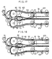
- Fig. 17 is an explanatory view illustrating a state of the sheet before being output from the sheet feed position after the state of Fig. 16.
- Fig. 18 is an explanatory view illustrating a state of the sheet being output to the lower reversing transport path from the sheet feed position after the state of Fig. 17.
- Fig. 19 is an explanatory view illustrating the state of the sheet being input to the sheet feed position through the upper sheet passage in the turnaround section after the state of Fig. 18.
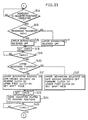
- Fig. 20 is a flowchart explaining the operations of the adjusting device.
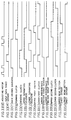
- Fig. 21 is a timing chart explaining the operations of the adjusting device.
- Fig. 22 is a flowchart showing the operations of LDU of Fig. 2.
- Fig. 23 is a flowchart showing the next operations of the LDU after the operations of Fig. 22.
- Fig. 24 is a flowchart showing the next operations of the LDU after the operations of Fig. 23.
- Fig. 25 is a flowchart showing the next operations of the LDU after the operations of Fig. 24.
- Fig. 26 is a flowchart showing the next operations of the LDU after the operations of Fig. 25.
- Fig. 27 is a flowchart showing the next operations of the LDU after the operations of Fig. 26.
- Fig. 28 is a flowchart showing the next operations of the LDU after the operations of Fig. 27.
- Fig. 29(a) is a flowchart explaining the operations of step 32 in Fig. 25, and Fig. 29(b) is a flowchart explaining the operations of step 44 in Fig. 26.
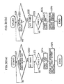
- Fig. 30(a) is a flowchart explaining the operations of step 65 in Fig. 27, and Fig. 30(b) is a flowchart explaining the operations of step 77 in Fig. 28.
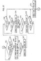
- Fig. 31 is a timing chart showing operations of the respective sections of the LDU.
- Fig. 32 is a timing chart showing the next operations of the respective sections of the LDU after the operations of Fig. 31.
- Fig. 33 is a timing chart showing the next operations of the respective sections of the LDU after the operations of Fig. 32.
- Fig. 34 is a timing chart showing the next operations of the respective sections of the LDU after the operations of Fig. 33.
- Fig. 35(a) is an explanatory view illustrating a state in which the LDU holds six A4-size laterally-fed sheets
- Fig. 35(b) is an explanatory view illustrating a state in which the LDU holds four A4-size longitudinally-fed sheets.
- Fig. 36 is a flowchart of linkage operations between the LDU and the main body of the digital copying machine.
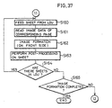
- Fig. 37 is a flowchart of the next linkage operations between the LDU and the main body of the digital copying machine after the operations of Fig. 36.
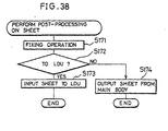
- Fig. 38 is a flowchart showing the operations of step 156 in Fig. 36 and the operations of step 163 in Fig. 37.
- Fig. 39 is a front view illustrating another example of the LDU.
- a digital copying machine 10 as a double-side image forming apparatus of this embodiment includes a scanner section 11, a laser printer section 12 as an image forming section, a multi-level sheet feed unit 13, and a sorter 14.
- the scanner section 11 is formed by a document platen 15 made of transparent glass, a recirculating document feeder (RDF) 16 compatible with double-side documents, and a scanner unit 17.
- a document platen 15 made of transparent glass
- RDF recirculating document feeder
- the RDF 16 automatically feeds a pile of a plurality of documents sheet by sheet to the scanner unit 17 in which one side or both sides of a document is (are) read according to an operator's request.
- the scanner unit 17 includes a lamp reflector assembly 21, a CCD (charge coupled device) 22 as a photoelectric converting element, a plurality of reflecting mirrors 23, and a lens 24.
- the lamp reflector assembly 21 applies light to a document.
- the reflecting mirror 23 guides reflected light from the document to the CCD 22.
- the lens 24 forms an image of the reflected light from the document on the CCD 22.
- the image data obtained by reading the image on the document by the scanner unit 17 is subjected to various operations in an image processing section (not shown) in the digital copying machine 10, and temporarily stored in a memory in the image processing section. Then, the image data in the memory is supplied to the laser printer section 12 upon an output instruction, and output as a reproduced image to a sheet.
- Image data transferred from an external information processing device for example, a word processor or micro computer is also stored in the memory. In this case, image data from the information processing device is output to a sheet.
- the laser printer section 12 includes a manual-feed tray 25, a laser writing unit 26, and an electrophotographic processing section 27 for forming an image.
- the laser writing unit 26 has a semiconductor laser, a polygon mirror, and an f- ⁇ lens (none of them are shown).
- the semiconductor laser emits laser light corresponding to the image data obtained from the memory in the image processing section.
- the polygon mirror deflects -the laser light at a constant angular velocity.
- the f- ⁇ lens is adjusted so that the laser light deflected at the constant angular velocity is deflected at a constant velocity on a photoreceptor drum 27a in the electrophotographic processing section 27.
- the electrophotographic processing section 27 includes a charger 27b, a developing device 27c, a transfer device 27d, a separating device 27e, a cleaning device 27f and a charge removing device 27g arranged in the well known manner around the photoreceptor drum 27a as well as a fixing device 32.
- a transport path 33 is disposed on a downstream side of the fixing device 32 in a sheet transporting direction.
- the transport path 33 is split into a transport path 34 and a transport path 35.
- the transport path 34 runs to the sorter 14, while the transport path 35 leads to the multi-level sheet feed unit 13.
- Also disposed on a sheet input side of a section between the photoreceptor drum 27a and the charger 27d are a register roller 40 for timely supplying a sheet to the section.
- the image data read out from the memory in the image processing section is output as laser light from the laser writing unit 26.
- the laser light scans the photoreceptor drum 27a which has been charged to a predetermined potential by the charger 27b so as to form an electrostatic latent image on a surface thereof.
- the electrostatic latent image is visualized as a toner image developed by toner supplied from the developing device 27c.
- the toner image is transferred to a sheet supplied from the multi-level sheet feed unit 13 through the register rollers 40 by the transfer device 27d.
- the sheet is then separated from the surface of the photoreceptor drum 27a by the separating device 27e. Toner remaining on the surface of the photoreceptor drum 27a is collected by the cleaning device 27f.
- Residual charges on the photoreceptor drum 27a are removed by the charge removing device 27g.
- the toner image transferred to the sheet is fixed to the sheet, and sent to the sorter 14 by the transport path 33, a switching gate 36 and the transport path 34, or to a loop duplex unit (LDU) 28 as a reverse sheet feeding device in the multi-level sheet feed unit 13 by the transport path 33, the switching gate 36 and the transport path 35.
- LDU loop duplex unit
- the multi-level sheet feed unit 13 includes the LDU 28, a first cassette 29, a second cassette 30, and an optional third cassette 31. Sheets stored in the first to third cassettes 29 to 31 are fed one by one from the topmost sheet to the electrophotographic processing section 27 in the laser printer section 12.
- Sheets fed from the first and second cassettes 29 and 30 are directed to and transported by a common transport path 37.
- a sheet output from the third cassette 31 is directed to and transported by a transport path 38.
- the transport paths 37 and 38 join together, and are connected to the rear end of a transport path 39.
- the front end of the transport path 39 joins a transport path 41 that is connected to the manual-feed tray 25 at a joint 42 on the sheet input side with respect to the register roller 40.
- a transport path 43 connected to a sheet output path 52 of the LDU 28 is also connected to the joint 42.
- the LDU 28 is movable in directions orthogonal to a paper surface of Fig. 1 by operating a holding section, not shown.
- the LDU 28 is thus freely inserted into and removed from the multi-level sheet feed unit 13.
- the LDU 28 includes a sheet input path 51, the sheet output path 52, a turnaround section 53, an upper reversing transport path 54 and a lower reversing transport path 55 as reversing transport paths, and a sheet guiding device 56 as sheet guiding means.
- the sheet input path 51 is connected to the transport path 35, while the sheet output path 52 is connected to the transport path 43.
- the turnaround section 53 is formed along a sheet transporting direction of the sheet input path 51.
- sheet input rollers 57 formed by a pair of rollers 57a and 57b, for transporting a sheet to the turnaround section 53.
- the turnaround section 53 When the sheet is supplied through the sheet input path 51, the turnaround section 53 reverses the leading and trailing edges of the sheet with respect to the sheet transporting direction by a switchback operation. As illustrated in Fig. 3, the turnaround section 53 includes an adjusting device 59, and a sheet input and output device 60.
- the adjusting device 59 is disposed on a supporting plate 58.
- the sheet input and output device 60 is positioned between the adjusting device 59 and the sheet input path 51.
- a side of the sheet input and output device 60 which is closer to the adjusting device 59 is a sheet input and output position of the turnaround section 53.
- the adjusting device 59 is provided for positioning a sheet which has been transported to a sheet feed position 61 on the supporting plate 58 by the sheet input and output device 60 in a correct position so as to prevent the sheet output from the turnaround section 53 from being fed in an oblique direction by the sheet input and output device 60. Therefore, as illustrated in Fig. 4, the adjusting device 59 includes a pair of adjusting plates 141, and an adjusting motor 142.
- the adjusting plates-141 are movable in directions orthogonal to the sheet transporting direction.
- the adjusting motor 142 drives the adjusting plates 141 to carry out adjusting operations.
- the driving force of the adjusting motor 142 is transmitted to the adjusting plates 141 through gears 143 and 144, three sprockets 145, a timing belt 146, a pinion gear 147, and rack gears 148 mounted on the adjusting plates 141, respectively.
- the adjusting plates 141 are moved in directions on a straight line so that they come closer to each other, by a rotational movement of the adjusting motor 142 in a direction, for example, by a forward rotation.
- the adjusting motor 142 is rotated in the reverse direction, the adjusting plates 141 are moved in directions on the straight line so that they are moved away from each other.
- Such movements of the adjusting plates 141 are guided by a movement of a pin 149 attached to the adjusting plate 141 along a slot 58a formed on the supporting plate 58.
- an adjusting-plate home position sensor 150 detects the state. The detection is executed when the adjusting-plate home position sensor 150 detects a plate-like sensor actuator 151 mounted on the adjusting plate 141.
- the sheet input and output device 60 includes a reversible roller 71, and upper and lower separable rollers 72 and 73 mounted as upper and lower auxiliary rollers above and below the reversible roller 71, respectively.
- the upper separable roller 72 and the lower separable roller 73 are capable of being pressed against and separated from the reversible roller 71.
- the reversible roller 71 is positioned to face an end of the sheet input path 51, closer to the turnaround section 53.
- the reversible rollers 71 are mounted on a driving shaft 74 rotated by a roller driving motor, not shown.
- the upper and lower separable rollers 72 and 73 are mounted on roller shafts 75 and 76, respectively.
- the roller shafts 75 and 76 are freely movable in upward and downward directions and pulled by a plurality of extension springs 77 in directions to which the upper and lower separable rollers 72 and 73 are pressed to come into contact with the reversible rollers 71.
- the separation movements of the upper and lower separable rollers 72 and 73 from the reversible rollers 71 are actuated by separation driving devices 78 and 79.
- the separation driving device 78 includes a rotation shaft 78a, a separation driving lever 78b mounted on the rotation shaft 78a, and an upper separating solenoid 78c.
- the separation driving device 79 includes a rotation shaft 79a, a separation driving lever 79b, and a lower separating solenoid 79c.
- an upper sheet passage 82 is formed by an intermediate sheet guide 80, located above and below the reversible roller 71, and an upper sheet guide 81 located below the upper separable roller 72.
- a lower sheet passage 84 is also formed by the intermediate sheet guide 80 and a lower sheet guide 83 positioned above the lower separable roller 73.
- the sheet guiding device 56 includes a switching gate 91 as a sheet guiding member and a gate driving device 92.
- the switching gate 91 is pivotable on an end thereof in the sheet input and output device 60.
- the switching gate 91 is movable to an upper-input and lower-output position as a first guide state or a first guide position shown by the solid line and to a lower-input and upper-output position as a second guide state or second guide position shown by the two-dot line.
- the upper-input and lower-output position is a position in which a sheet supplied through the sheet input path 51 is guided to the upper sheet passage 82, while a sheet output from the turnaround section 53 through the lower sheet passage 84 is guided to the lower reversing transport path 55.
- the lower-input and upper-output position is a position in which a sheet supplied from the sheet input path 51 is guided to the lower sheet passage 84, while the sheet output from the turnaround section 53 through the upper sheet passage 82 to the upper reversing transport path 54.
- the gate driving device 92 includes a rotation shaft 92a, an extension spring 92b, and a gate driving solenoid 92c.
- a switching gate 92 is mounted on the rotation shaft 92a.
- the extension spring 92b rotates the rotation shaft 92a by pulling so that the switching gate 91 is located in the upper-input and lower-output position.
- the gate driving solenoid 92c When the gate driving solenoid 92c is turned on, it rotates the switching gate 91 to the lower-input and upper-output position against the pulling force of the extension spring 92b.
- the switching gate 91 is driven by the extension string 92b, it is positioned in the upper-input and lower-output position by a stopper, not shown.
- the upper and lower reversing transport paths 54 and 55 separate from each other at the end point of the sheet input path 51, and extend toward upper and lower directions from the end point, respectively. Then, the upper and lower reversing transport paths 54 and 55 pass over and under the turnaround section 53, and join together at the starting point of the sheet output path 52.
- the upper reversing transport path 54 includes a front section 101, an intermediate section 102 and a rear section 103.
- the front section 101 has a circular shape and is formed between a circular sheet guide 101a and a turn roller 107a with a large diameter, located in the inner side of the circular sheet guide 101a.
- An auxiliary roller 107b which makes a pair with the turn roller 107a is pressed against the turn roller 107a.
- the rollers 107a and 107b form an upper first transport rollers 107 as transporting means.
- the structure of the upper first transport rollers 107 is shown in Fig. 5.
- the turn roller 107a and the auxiliary roller 107b are mounted on roller shafts 107c and 107d, respectively.
- the auxiliary rollers 107b are pressed against the turn rollers 107a by extension springs 107e attached to the roller shaft 107d.
- the intermediate section 102 is formed by an intermediate upper sheet guide 102a as a movable member, an intermediate lower-front section sheet guide 102b and an intermediate lower-rear section sheet guide 102c.
- the intermediate lower-front section sheet guide 102b and the intermediate lower-rear section sheet guide 102c function as fixing members.
- the intermediate upper sheet guide 102a extends from the end point of the front section 101 to the starting point of the rear section 103.
- the intermediate lower-front section sheet guide 102b and the intermediate lower-rear section sheet guide 102c are positioned to face the intermediate upper sheet guide 102a.
- second to fourth upper transport rollers 108 to 110 are installed from the front toward the back of the intermediate section 102.
- a driving roller 108a of the upper second transport rollers 108 is mounted on the intermediate lower-front section sheet guide 102b.
- Driving rollers 109a and 110a of the upper third and fourth transport rollers 109 and 110 are mounted on the intermediate lower-rear section sheet guide 102c.
- Driven rollers 108b to 110b of the upper second to fourth transport rollers 108 to 110 are mounted on the intermediate upper sheet guide 102a.
- the intermediate upper sheet guide 102a is rotatable on an end thereof in the rear section 103 with respect to the intermediate lower-front section sheet guide 102b and the intermediate lower-rear section sheet guide 102c. Therefore, if a paper jam occurs in the upper reversing transport path 54, the paper jam is fixed by opening the intermediate upper sheet guide 102a to release the intermediate section 102. In this case, the driven rollers 108b to 110b of the upper second to fourth transport rollers 108 to 110 are also moved together with the intermediate upper sheet guide 102a.
- the rear section 103 is formed by a rear upper sheet guide 103a and a rear lower sheet guide 103b, and extends from the end point of the intermediate section 102 to the starting point of the sheet output path 52.
- upper fifth rollers 111 including a driving roller 111a and a driven roller lllb are provided.
- the lower reversing transport path 55 includes a front section 104, an intermediate section 105, and a rear section 106.
- the front section 104 has a circular sheet guide 104a corresponding to the circular sheet guide 101a.
- lower first transport rollers 112 including a turn roller 112a and an auxiliary roller 112b are provided in the front section 104.
- the lower first transport rollers 112 correspond to the upper first transport rollers 107.
- the structure of the lower first transport rollers 112 is shown in Fig. 5.
- the turn roller 112a and the auxiliary roller 112b are mounted on roller shafts 112c and 112d, respectively.
- the auxiliary roller 112b is pressed against the turn roller 112a by an extension spring 112e attached to the roller shaft 112d of the auxiliary roller 112b.
- the intermediate section 105 is formed by an intermediate lower sheet guide 105a as a movable member, an intermediate upper-front section sheet guide 105b and an intermediate upper-rear section sheet guide 105c.
- the intermediate upper-front section sheet guide 105b and the intermediate upper-rear section sheet guide 105c function as fixing members.
- the intermediate lower sheet guide 105a, the intermediate upper-front section sheet guide 105b, and the intermediate upper-rear section sheet guide 105c correspond to the intermediate upper sheet guide 102a, the intermediate lower-front section sheet guide 102b and the intermediate lower-rear section sheet guide 102c, respectively.
- lower second to fourth transport rollers 113 to 116 corresponding to the upper second to fourth transport rollers 108 to 110 are installed.
- the intermediate lower sheet guide 105a is rotatable with respect to the intermediate upper-front section sheet guide 105b and the intermediate upper-rear section sheet guide 105c.
- One of the sides of the intermediate lower sheet guide 105a for example, the back side in Fig. 2, is fixed, and the opposite side thereof is movable in the downward direction. Namely, the intermediate lower sheet guide 105a is opened by moving the movable side thereof in the downward direction.
- driving rollers 113a to 116a are mounted on the intermediate upper-front section sheet guide 105b and the intermediate upper-rear section sheet guide 105c, while driven rollers 113b to 116b are mounted on the intermediate lower sheet guide 105a.
- the rear section 106 is formed by a rear lower sheet guide 106a, and a rear upper sheet guide 106b.
- Lower fifth transport rollers 116 formed by the driving roller 116a and the driven roller 116b are provided.
- the front section 101 and the intermediate section 102 of the upper reversing transport path 54 and the front section 104 and the intermediate section 104 of the lower reversing transport path 55 are symmetrically arranged with respect to the turnaround section 53.
- the total length of the upper reversing transport path 54 is set equal to the total length of the lower reversing transport path 55.
- the driving roller 110a is mounted on a rotating shaft 117, and rotated when a driving force is input through a gear 118 attached to the rotating shaft 117.
- the driven roller 110b is rotatably mounted on a roller shaft 120 supported on the intermediate upper sheet guide 102a by a structure, not shown.
- the driven roller 110b is pressed against the driving roller 110a by a plate spring 119 pushing the roller shaft 120. Consequently, when a paper jam occurs, an operator releases the intermediate upper sheet guide 102a and removes the paper causing the paper jam in the upper reversing transport path 54.
- the driven roller 110b is suitably pressed against the driving roller 110a. Moreover, since the driven roller 110b is mounted on the intermediate upper sheet guide 102a which is opened when fixing a paper jam, the installation structure of the upper fourth transport rollers 110 is simplified. Thus, the structure is also adopted in the upper second and third transport rollers 108 and 109 and the lower second to fourth transport rollers 113 to 116.
- the LDU 28 includes an input path sheet sensor 121, a turnaround section sheet sensor 122, an upper intermediate section sheet sensor 123, an upper rear section sheet sensor 124, a lower intermediate section sheet sensor 125, and a lower rear section sheet sensor 126.
- the input path sheet sensor 121 is provided in the sheet input path 51.
- the turnaround section sheet sensor 122 is positioned in the joint of the upper sheet passage 82 and the lower sheet passage 84 in the turnaround section 53.
- the upper intermediate section sheet sensor 123 and the upper rear section sheet sensor 124 are mounted in the intermediate section 102 and the rear section 103 in the upper reversing transport path 54, respectively.
- the lower intermediate section sheet sensor 125 and the lower rear section sheet sensor 126 are disposed in the intermediate transport path 105 and the rear transport path 106 in the lower reversing transport path 55.
- the upper first to fifth transport rollers 107 to 111 in the upper reversing transport path 54 and the corresponding lower first to fifth transport rollers 112 to 116 in the lower reversing transport path 55 are located in corresponding positions equally separated from the starting point of the upper and lower reversing transport paths 54 and 55, respectively.
- the upper intermediate section sheet sensor 123 and upper rear section sheet sensor 124 in the upper reversing transport path 54 and the corresponding lower intermediate section sheet sensor 125 and the lower rear section sheet sensor 126 in the lower reversing transport path 55 are located in corresponding positions equally separated from the starting point of the upper and lower reversing transport paths 54 and 55, respectively.
- the LDU 28 includes an LDU controller 131, shown in Fig. 8, which constitutes controlling means together with a main body controller, to be described later.
- the LDU controller 131 includes a CPU (central processing unit), a ROM (read only memory) and a RAM (random access memory), not shown.
- the ROM stores a control program of the CPU.
- the RAM is a memory area in which various information related to control operations of the CPU is stored.
- the LDU controller 131 Connected to the LDU controller 131 are the input path sheet sensor 121, the turnaround section sheet sensor 122, the upper intermediate section sheet sensor 123, the upper rear section sheet sensor 124, the lower intermediate section sheet sensor 125, and the lower rear section sheet sensor 126. Also connected to the LDU controller 131 are a roller driving motor 132 as a driving source of the respective rollers in the LDU 28, an upper first clutch 133, an upper second clutch 134, a lower first clutch 135, a lower second clutch 136, the upper separating solenoid 78c of the separation driving device 78, a lower separating solenoid 79c of the separation driving device 79, a forward clutch 137, a reverse clutch 138, the adjusting motor 142 and a main body controller 161.
- the driving force of the roller driving motor 132 is transmitted to the turn roller 107a of the upper first transport rollers 107 and the driving rollers 108a and 109a of the upper second and third transport rollers 108 and 109 through the upper first clutch 133, and transmitted to the upper fourth and fifth rollers 110 and 111 through the upper second clutch 134.
- the driving force of the roller driving motor 132 is transmitted to the turn roller 112a of the lower first transport rollers 112, the driving rollers 113a and 114a of the lower second and third transport rollers 113 and 114 through the lower first clutch 135, and to the lower fourth and fifth transport rollers 115 and 116 through the lower second clutch 136.
- the driving force of the roller driving motor 132 is transmitted to the reversible roller 71 through the forward clutch 137 or the reverse clutch 138.
- the forward clutch 137 transmits the driving force of the roller driving motor 132 to the reversible roller 71 so that the reversible roller 71 is rotated in a clockwise direction, for example, a forward direction in Fig. 2.
- the reverse clutch 138 transmits the driving force of the roller driving motor 132 to the reversible roller 71 so that the reversible roller 71 is rotated in a counterclockwise direction, for example, in the reverse direction in Fig. 2.
- the adjusting motor 142 drives the adjusting plates 141 to operate adjusting operations.
- the first sheet input from the sheet input path 51 is guided to the upper sheet passage 82 by the switching gate 91 which is switched to the upper-input and lower-output position.
- the sheet is transported to the sheet feed position 61 by the upper separable roller 72 pressed against the reversible roller 71 and the reversible roller 71 rotating in the clockwise direction or the forward direction in Fig. 9. Thereafter, the reversible roller 71 is stopped. In this state, as illustrated in Fig. 10, the trailing edge of the sheet is nipped between the reversible roller 71 and the upper separable roller 72.
- the reversible roller 71 is controlled to be stopped when a predetermined time according to the size of a sheet elapses after the leading edge of the sheet is detected by the input path sheet sensor 121 in the sheet input path 51.
- the predetermined time is determined by the LDU controller 131 on the basis of the size of a sheet supplied from the first to third cassettes 29 to 31 or the manual-feed tray 25, and a transporting speed of sheet in the sheet input and output device 60.
- the adjusting device 59 is actuated. As a result, the obliquely fed sheet is corrected to a predetermined position by the adjusting plates 141 of the adjusting device 59.
- the upper separable roller 72 is pressed against the reversible roller 71, while the switching gate 91 is switched to the lower-input and upper-output position. Subsequently, the adjusting plates 141 return to the standby positions.
- the reversible roller 71 is rotated in the counterclockwise direction or the reverse direction, and the sheet in the sheet fed position 61 is guided to the switching gate 91 and transported to the upper reversing transport path 54.
- the sheet is then input into the upper reversing transport path 54 by the rotations of the upper first to third transport rollers 107 to 109.
- the sheet is output from the sheet output path 52 at a predetermined time and supplied to the laser printer section 12 by the rotations of the upper fourth and fifth transport rollers 110 to 111.
- the switching gate 91 when the switching gate 91 is switched to the lower-input and upper-output position, as illustrated in Fig. 14, the sheet supplied from the sheet input path 51 is guided to the lower sheet passage 84. Next, the sheet is transported to the sheet feed position 61 by the lower separable roller 73 pressed against the reversible roller 71 and the reversible roller 71 rotating in the reverse direction. Then, the reversible roller 71 is stopped. In this state, as illustrated in Fig. 15, the trailing edge of the sheet is nipped between the reversible roller 71 and the lower separable roller 73. In this case, the reversible roller 71 is stopped by the same control as mentioned above.
- the lower separable roller 73 is separated from the reversible roller 71 by several mm, and the adjusting plates 141 of the adjusting device 59 are moved to the adjusted positions. As a result, the sheet is located in the predetermined position.
- the reversible roller 71 rotates in the forward direction, and the sheet in the sheet feed position 61 is guided by the switching gate 91 and transported to the lower reversing transport path 55.
- the sheet is input into the lower reversing transport path 55 by the rotations of the lower first to third transport rollers 112 to 114.
- the sheet is then output from the sheet output path 52 at a predetermined time by the rotations of the lower fourth and fifth transport rollers 115 and 116, and supplied to the laser printer section 12.
- the third sheet is input to the sheet feed position 61 through the upper sheet passage 82.
- This operation is the same as that shown in Fig. 9, and then the above-mentioned operations are repeated. Namely, sheets successively supplied from the sheet input path 51 alternately pass through the upper sheet passage 82 and the lower sheet passage 84 according to a switching operation of the switching gate 91, and are fed to the sheet feed position 61. Thereafter, the sheets are output from the sheet feed position 61 to the upper reversing transport path 54 and the lower reversing transport path 55 alternately.
- the adjusting motor 142 is rotated and the adjusting plates 141 are moved to the standby positions where they are detected by the adjusting-plate home position sensor 150. This operation is controlled by the LDU controller 131.
- the door switch is installed on a front door of the digital copying machine 10 provided for protection and maintenance purposes, and turned on when the front door is closed.
- the size of a sheet to be used for copying is input to the LDU controller 131.
- the LDU controller 131 rotates the adjusting motor 142 in the forward direction so as to move the adjusting plates 141 to the standby positions. These positions are defined by arranging the distance between raised sections 141a shown in Fig. 4 of the adjusting plates 141, which come into contact with the side edges of a sheet when adjusted, to be 5 mm longer than the width of the sheet transported to the sheet feed position 61.
- the adjusting device 59 promptly performs the subsequent adjusting operations. Moreover, since the standby positions are marginally set with respect to the sheet width, even if a sheet is obliquely fed to the sheet feed position 61 or a fed to a slightly shifted position, the sheet is not caught by the adjusting plates 141, thereby preventing a paper jam.
- the LDU controller 131 When the sheet is detected by the input path sheet sensor 121 and is transported to the sheet feed position 61 with the forward or reverse rotation of the reversible roller 71, the LDU controller 131 turns off the forward clutch 137 or the reverse clutch 138 so as to stop the rotation of the reversible roller 71 (step 201). Consequently, the sheet is stopped between the adjusting plates 141 in the standby positions. Moreover, the LDU controller 131 turns on the upper separating solenoid 78c or the lower separating solenoid 79c simultaneously with the operation of step 201 so as to separate the upper separable roller 72 or the lower separable roller 73 to which the sheet has been transported, from the reversible roller 71 (step 202). As a result, the sheet becomes freely movable.
- the LDU controller 131 sets an internal timer therein for a time T 1 taken by the completion of operations of the reversible roller 71 and the upper separable roller 72 or the lower separable roller 73 (step 203).
- the LDU controller 131 rotates the adjusting roller 142 in the forward direction so as to move the adjusting plates 141 to adjusted positions corresponding to the size of the sheet (step 205).
- the sheet is located in the predetermined position. Namely, the sheet is adjusted to a correct position so that the sheet is stably transported from the sheet feed position 61.
- the adjusting motor 142 is a pulse motor and moves the adjusting plates 141 by, for example, 0.25 mm with the rotations corresponding to one pulse, the adjusting motor 142 is rotated for a time period corresponding to 20 pulses.
- the LDU controller 131 When the movements of the adjusting plates 141 to the adjusted positions are completed, the LDU controller 131 immediately turns off the upper separating solenoid 78c or the lower separating solenoid 79c which was turned on in step 202 to press the upper separable roller 72 or the lower separable roller 73 against the reversible roller 71 (step 206). At this time, the LDU controller 131 sets the timer for a predetermined time T 2 taken by pressing the upper separable roller 72 or the lower separable roller 73 against the reversible roller 71 in the operation of step 206 (step 207). When the set time elapses, as illustrated in Fig. 12 or 17, the sheet in the sheet feed position 61 is adjusted to the predetermined position and fixed so that the sheet is ready to be correctly transported from the sheet feed position 61.
- the LDU controller 131 When the set time elapses (step 208), the LDU controller 131 turns on the forward clutch 137 or the reverse clutch 138 to rotate the reversible roller 71 in a direction to which the sheet is to be output, and turns off the lower separating solenoid 79c or the upper separating solenoid 78c to separate from the reversible roller 71 the lower separable roller 73 or the upper separable roller 72, which is not in use.
- the LDU roller 131 turns on the upper first clutch 133 or the lower first clutch 135 to rotate the upper first to third transport rollers 107 to 109 or the lower first to third transport rollers. 112 to 114 in the reversing transport path 54 or 55 being used for the transport of sheet (step 209).
- the LDU controller 131 sets the timer for a predetermined time T 3 (step 210) and moves the adjusting plates 141 to the standby positions (step 211).
- the reason for separating the lower separable roller 73 or the upper separable roller 72, which is not in use, from the reversible roller 71 in step 209 is to prevent transporting of a standby sheet that is stopped between the above-mentioned reversible roller 71 and the lower separable roller 73 or the upper separable roller 72.
- the adjusting motor 142 is rotated in the reverse direction by a time period corresponding to 20 pulses. As a result, the adjusting plates 141 enter into the standby state for the transport of the next sheet to the sheet feed position 61.
- the LDU controller 131 turns off the forward clutch 137 or the reverse clutch 138 to stop the reversible roller 71, and turns off the upper first clutch 133 or the lower first clutch 135 to stop the upper first to third transport rollers 107 to 109 or the lower first to third transport rollers 112 to 114 in the reversing transport path 54 or 55 being used for the transport of sheet.
- the LDU controller 131 turns on the upper or lower separating solenoid 78c or 79c to separate the upper or lower separable roller 72 or 73 which has output the sheet from the reversible roller 71 (step 213). As a result, the sheet is stopped between the upper first transport rollers 107 or the lower first transport rollers 112.
- the timing of the operations is shown in Fig. 21.
- Figs. 31 to 34 show an example in which six sheets are subsequently held in the upper and lower reversing transport paths 54 and 55 in the manner as shown in Fig. 35(a).
- a register roller clutch operated at the operational timing shown in Fig. 31(a) transmits the driving force of a driving source (not shown) to the register roller 40.
- the register roller 40 is rotated by turning on the register roller clutch.
- a separating section sheet sensor (not shown) operated at the operational timing shown in Fig. 31(b) is disposed on the sheet transporting side of the separating device 27e and detects the passage of sheet.
- steps 9 to 22 of Fig. 22 correspond to the above-mentioned operations shown in Fig. 20.
- a toner image is formed on a surface of a photoreceptor drum 27a through a predetermined copying process in the laser printer section 12 shown in Fig. 1. Then, as illustrated in Fig. 31, when the register roller clutch is turned on (see Fig. 31(a)), the adjusting plates 141 of the adjusting device 59 return to the standby positions (see Fig. 31(b)).
- the register roller clutch When the register roller clutch is turned on, the register roller 40 rotates, and a sheet held by the register roller 40 is transported to a section between the photoreceptor drum 27a and the transfer device 27d. Next, the toner image on the surface of the photoreceptor drum 27a is transferred to the sheet by the transfer device 27d, and the sheet is separated from the surface of the photoreceptor drum 27a by the separating device 27e. Thereafter, the sheet is fed to the fixing device 32 and subjected to a fixing operation. After the fixing operation, the sheet is guided to the transport path 35 by the switching gate 36, and transported to the sheet input path 51.
- the switching gate 36 is switched so that the sheet is guided toward the transport path 35 (see Fig. 31(c)).
- the LDU controller 131 judges whether the upper reversing transport path 54 is to be used, i.e., whether the upper reversing transport path 54 or the lower reversing transport path 55 is to be used for transporting the sheet (step 2).
- the LDU 28 transports sheets by alternately using the upper reversing transport path 54 and the lower reversing transport path 55 according to the judgement.
- the LDU controller 131 turns off the gate driving solenoid 92c in the sheet guiding device 56, and switches the switching gate 91 to the upper-input and lower-output position. Moreover, the LDU controller 131 turns off the upper separating solenoid 78c in the separation driving device 78 to press the upper separable roller 72 against the reversible roller 71, and turns on the forward clutch 137 to rotate the reversible roller 71 in the forward direction (step 3).
- the LDU controller 131 turns on the gate driving solenoid 92c and switches the switching gate 91 to the lower-input and upper-output position. Then, the LDU controller 131 turns off the lower separating solenoid 79c to press the lower separable roller 73 against the reversible roller 71, and turns on the reverse clutch 138 to rotate the reversible roller 71 in the reverse direction (step 4).
- the LDU controller 131 sets the internal timer for a time taken by bringing the sheet to the sheet feed position 61 and the trailing edge of the sheet to be held between the reversible roller 71 and the upper separable roller 72, i.e., by bringing the sheet into the state shown in Fig. 10 (step 6).
- step 7 When the set time elapses (step 7), if the upper reversing transport path 54 is in use (step 8), the LDU controller 131 turns on the upper separating solenoid 78c to separate the upper separable roller 72 from the reversible roller 71, and turns off the forward clutch 137 to stop the reversible roller 71 (step 9).
- the LDU controller 131 turns on the lower separating solenoid 79c to separate the lower separable roller 73 from the reversible roller 71, and turns off the reverse clutch 138 to stop the reversible roller 71 (step 10).
- the LDU controller 131 sets the timer for a time taken by the completion of the operation in step 9 or 10 (step 11).
- the set time elapses, for example, as illustrated in Fig. 11 or 16, the fixed state of the sheet is released.
- the LDU controller 131 rotates the adjusting motor 142 to move the adjusting plates 141 to the adjusted positions (step 13).
- the adjusted positions vary depending on the sizes of sheets.
- step 14 when the movements of the adjusting plates 141 to the adjusted positions are completed (step 14), if the upper reversing transport path 54 is in use (step 15), the LDU controller 131 immediately turns off the upper separating solenoid 78c (step 16). On the other hand, if the lower reversing transport path 55 is in use (step 15), the LDU controller 131 immediately turns off the lower separating solenoid 79c (step 17).
- the LDU controller 131 sets the timer for a time taken by pressing the upper separable roller 72 or the lower separable roller 73 against the reversible roller 71 in the operation of step 17 or 18 (step 18).
- the set time elapses, as illustrated in Fig. 12 or 17, the sheet in the sheet feed position 61 is adjusted and fixed in the predetermined position.
- the LDU controller 131 turns on the lower separating solenoid 79c to separate the lower separable roller 73 from the reversible roller 71, and turns on the gate driving solenoid 92c to switch the switching gate 91 to the lower-input and upper-output position. Moreover, the LDU controller 131 turns on the reverse clutch 138 to rotate the reversible roller 71 in the reverse direction. Furthermore, the LDU controller 131 turns on the upper first clutch 133 to rotate the upper first to third transport rollers 107 to 109, and sets a shift mode (step 21).
- the LDU controller 131 turns on the upper separating solenoid 78c to separate the upper separable roller 72 from the reversible roller 71. Moreover, the LDU controller 131 turns off the gate driving solenoid 92c to switch the switching gate 91 to the upper-input and lower-output position. Furthermore, the LDU controller 131 turns on the forward clutch 137 to rotate the reversible roller 71 in the forward direction, turns on the lower first clutch 135 to rotate the lower first to third transport rollers 112 to 114, and sets the shift mode (step 22).
- the sheet in the sheet feed position 61 is fed to the upper reversing transport path 54 or the lower reversing transport path 55 by the operation in step 21 or 22.
- the reason for separating one of the upper and lower separable rollers 72 and 73, which is not in use in outputting the sheet, from the reversible roller 71 in the operation in step 21 or 22 is as follows. With this arrangement, when the sheet ready for output is nipped between the reversible roller 71 and the lower or upper separable roller 73 or 72, which is not being used for the output of the sheet, the movement of the sheet is prevented.
- the position of the switching gate 91 and the rotating direction of the reversible roller 71 are selected so that the sheet is input to the sheet feed position 61 through one of the lower and upper sheet passages 83 and 82, which is not being used for outputting the sheet. Therefore, when the input and output of sheets are simultaneously performed, the lower separable roller 72 or the upper separable roller 73 on the sheet input side is pressed against the reversible roller 71.
- the former sheet being transported is controlled to be shifted in a forward direction, for example, by about 30 mm to feed the latter sheet to a position where it is nipped between the upper first transport rollers 107, thereby preventing the sheets from overlapping.
- the LDU controller 131 sets the timer for a time taken from the start of outputting the sheet from the sheet feed position 61 to the transport of sheet to the above-mentioned position where the sheet is satisfactorily nipped between the upper first transport rollers 107 or the lower first transport rollers 112 (step 23). Then, the LDU controller 131 moves the adjusting plates 141 to the standby positions (step 24). When the set time elapses (step 25), as illustrated in Fig. 24, if the upper reversing transport path 54 is in use (step 26), the LDU controller 131 turns on the upper separating solenoid 78c to separate the upper separable roller 72 from the reversible roller 71 (step 27).
- a stop mode for stopping the transport of sheet is set (step 28) in order to prevent the sheets from overlapping. Then, the LDU controller 131 turns off the upper first clutch 133 to stop the upper first to third transport rollers 107 to 109, and clears the shift mode (step 29).
- the upper reversing transport path 54 is capable of holding three sheets, the state is observed when the third sheet is to be input into the upper reversing transport path 54. In this case, the sheets are detected by the upper intermediate section sheet sensor 123 and the upper rear section sheet sensor 124, respectively. It is also possible to input the sheet to the sheet feed position 61 through the lower sheet passage 84 by the reversible roller 71 rotating in the reverse direction and the lower separable roller 73 pressed against the reversible roller 71.
- the LDU controller 131 turns on the upper first clutch 133 to continue the transport of sheet (step 30).
- the LDU controller 131 sets an upper intermediate section sheet sensor monitor, and sets the timer for a predetermined time (step 32).
- the upper intermediate section sheet sensor monitor is controlled in the manner shown in the flowchart of Fig. 29(a).
- the LDU controller 131 sets the timer for a predetermined time, for example, the time taken to further transport the sheet to a more suitable position (step 102).
- the LDU controller 131 turns off the upper first clutch 133 so as to stop the upper first to third transport rollers 107 to 109 which have finished the transport of sheet (step 104), and clears the upper intermediate section sheet sensor monitor (step 105).
- the LDU controller 131 When the time set in step 32 elapses, the LDU controller 131 temporarily turns off the upper first clutch 133 to stop the upper first to third transport rollers 107 to 109.
- the LDU controller 131 sets the stop mode (step 35). At this time, if the shift mode is also to be set, the LDU controller 131 sets the shift mode (step 36), and turns on the upper first clutch 133 so as to rotate the upper first to third transport rollers 107 to 109 (step 37). Simultaneously, the LDU controller 131 sets the timer for a predetermined time taken by shifting the sheet (step 38). When the set time elapses (step 39), the LDU controller 131 turns off the upper first clutch 133 to stop the first to third transport rollers 107 to 109 (step 40).
- step 41 the LDU controller 131 is held in the standby state until when the sheet is to be forwarded, i.e., when the stop mode is to be cancelled. Then, when the sheet in the forward position is transported and the stop mode is cancelled, the operational step is forwarded to step 42. Whereas when the shift mode should not be set in step 36, i.e., when no sheet is further input to the upper reversing transport path 54, the LDU controller 131 waits the cancellation of the stop mode, and then proceeds to step 42.
- the LDU controller 131 turns on the upper first clutch 133 to rotate the upper first to third transport rollers 107 to 109, and turns on the upper second clutch 134 to rotate the upper fourth to fifth transport rollers 110 and 111 (step 42).
- the LDU controller 131 sets the upper rear section sheet sensor monitor (step 44).
- the LDU controller 131 sets the timer for a predetermined time (step 112). Then, when the set time elapses (step 113), the LDU controller 131 turns off the upper second clutch 134 to stop the upper fourth and fifth transport rollers 110 and 111 (step 114) which have completed the transport of sheet, and clears the upper rear section sheet sensor monitor (step 115).
- the LDU controller 131 turns off the upper second clutch 134 to stop the upper fourth and fifth transport rollers 110 and 111 (step 48).
- the LDU controller 131 sets the timer for a predetermined time (step 46).
- the LDU controller 131 stops the upper second clutch 134 (step 48). This operation is performed to control the short sheet to be shifted in advance independently of whether the shift mode is set or not.
- the responsibility to a sheet output request from the main body controller 161 for controlling the laser printer section 12 is improved by a degree equivalent to the moving time corresponding to the amount of shift.
- the LDU controller 131 turns off the upper first clutch 133 and stops the upper third transport rollers 109 (step 50) due to the following reason.
- the sheet is long, the trailing edge thereof is nipped between the upper third transport rollers 109, and therefore the transporting operation of the transport rollers 109 is also stopped. As a result, the sheet is stopped over the rear section 103 and the intermediate section 102 of the upper reversing transport path 54.
- the LDU controller 131 When the shift mode is set (step 51), the LDU controller 131 turns on the upper first and second clutches 133 and 134 to rotate the upper first to fifth transport rollers 107 to 111 (step 52). Simultaneously, the LDU controller 131 sets the timer for a predetermined time (step 53). When the set time elapses (step 54), the LDU controller 131 turns off the upper first and second clutches 133 and 134 to stop the upper first to fifth transport rollers 107 to 111 (step 55).
- the LDU controller 131 turns on the upper first clutch 133 to rotate the upper third transport rollers 109 (step 57), and turns on the upper second clutch 134 to rotate the upper fourth and fifth transport rollers 110 and 111 (step 59).
- a long sheet located in the most forwarded position in the upper reversing transport path 54 is moved to the sheet output path 52, and supplied through the transport path 43 to the laser printer section 12.
- the upper first and second clutches 133 and 134 are then controlled to be turned off by the upper intermediate section sheet sensor monitor and the upper rear section sheet sensor monitor shown in Figs. 29(a) and 29(b), respectively.
- the LDU controller 131 waits the sheet output request from the main body controller 161 in step 56, and outputs the sheet in steps 57 and 59. On the other hand, if there is no sheet output request in step 56, the operational step returns to step 51. In this case, however, if the operations of steps 51 to 55 have been performed once, they are not repeated.
- the LDU controller 131 waits until a sheet output request is sent by the main body controller 161 (step 58).
- the LDU controller 131 turns on the upper second clutch 134 to rotate the upper fourth and fifth transport rollers 110 and 111 (step 59).
- a short sheet located in the most forwarded position in the upper reversing transport path 54 is supplied to the laser printer section 12.
- step 26 when the lower reversing transport path 55 is used in step 26, the operation of step 60 shown in Fig. 24 through the operations shown in Fig 27 to the operation of step 92 of Fig. 28 are performed. These operations correspond to the above-mentioned operations in steps 27 to 59.
- step 60 When the lower reversing transport path 55 is used in step 26, the lower separating solenoid 79c is turned on, and the lower separable roller 73 is separated from the reversible roller 71 (step 60).
- the LDU controller 131 turns off the lower first clutch 135 so as to stop the lower first to third transport rollers 112 to 114, and clears the shift mode (step 62). In this case, it is possible to input a sheet to the sheet feed position 61 through the upper sheet passage 82 by the reversible roller 71 and the upper separable roller 72 pressed against the reversible roller 71.
- the LDU controller 131 turns on the first clutch 135, and continues the transport of the sheet (step 63).
- the LDU controller 131 sets the lower intermediate sheet sensor monitor and the timer for a predetermined time (step 65).
- step 121 When the lower intermediate sheet sensor 125 is turned off (step 121), the timer is set for a predetermined time (step 122). When the set time elapses (step 123), the lower first clutch 135 is turned off, and the lower first to third transport rollers 112 to 114 which have completed the sheet transporting operations are stopped (step 124). Then, the lower intermediate sheet sensor monitor is cleared (step 125).
- the LDU controller 131 When the time set in step 65 is measured, the LDU controller 131 temporarily turns off the lower first clutch 135 so as to stop the lower first to third transport rollers 112 to 114.
- the LDU controller 131 When inputting a sheet, if there is another sheet in a forward position in the sheet transporting direction of the lower reversing transport path 55, the LDU controller 131 sets the stop mode (step 68). At this time, if the shift mode is also to be set, the LDU controller 131 sets the shift mode (steps 69), and turns on the lower first clutch 135 so as to rotate the lower first to third transport rollers 112 to 114 (step 70). Simultaneously, the LDU controller 131 sets the timer for a predetermined time (step 71). When the set time elapses (step 72), the lower first clutch 135 is turned off, and the lower first to third transport rollers 112 to 114 are stopped (step 73).
- step 74 the LDU controller 131 waits until when the sheet is to be fed forward, i.e., when the stop mode is to be cancelled. When the stop mode is cancelled, the operational step proceeds to step 75. Whereas when the shift mode should not to be set in step 69, the LDU controller 131 also waits the cancellation of the stop mode and then proceeds to step 75.
- the LDU controller 131 turns on the lower first clutch 135 so as to rotate the lower first to third transport rollers 112 to 114 and turns on the lower second clutch 136 so as to rotate the lower fourth and fifth transport rollers 115 and 116 (step 75).
- the LDU controller 131 sets the lower rear section sheet sensor monitor (step 77).
- the LDU controller 131 sets the timer for a predetermined time (step 132). Then, when the set time elapses (step 133), the LDU controller 131 turns off the lower second clutch 136 to stop the lower fourth and fifth transport rollers 115 and 116 (step 134) which have completed the transport of sheet, and clears the lower rear section sheet sensor monitor (step 135).
- the LDU controller 131 turns off the lower second clutch 136 to stop the lower fourth and fifth transport rollers 115 and 116 (step 81).
- the LDU controller 131 sets the timer for a predetermined time (step 79).
- the LDU controller 131 turns off the lower second clutch 136 (step 81). This operation is performed due to the reason mentioned above for steps 46 and 47.
- the LDU controller 131 turns off the lower first clutch 135 and stops the lower third transport rollers 114 (step 83).
- the trailing edge thereof is nipped between the lower third transport rollers 114, and therefore the transporting operation of the lower transport rollers 114 is also stopped.
- the sheet is stopped over the rear section 106 and the intermediate section 105 of the lower reversing transport path 55.
- the LDU controller 131 When the shift mode is set (step 84), the LDU controller 131 turns on the lower first and second clutches 135 and 136 to rotate the lower first to fifth transport rollers 112 to 116 (step 85). Simultaneously, the LDU controller 131 sets the timer for a predetermined time (step 86). When the set time elapses (step 87), the LDU controller 131 turns off the lower first and second clutches 135 and 136 to stop the lower first to fifth transport rollers 112 to 116 (step 88).
- the LDU controller 131 turns on the lower first clutch 135 to rotate the lower third transport rollers 114 (step 90), and turns on the lower second clutch 136 to rotate the lower fourth and fifth transport rollers 115 and 116 (step 92).
- a long sheet located in the most forwarded position in the lower reversing transport path 55 is moved to the sheet output path 52, and supplied through the transport path 43 to the laser printer section 12.
- the lower first and second clutches 135 and 136 are then controlled to be turned off by the lower intermediate section sheet sensor monitor and the lower rear section sheet sensor monitor shown in Figs. 30(a) and 30(b), respectively.
- step 84 the LDU controller 131 waits the sheet output request from the main body controller 161 in step 89, and outputs the sheet in steps 90 and 92. On the other hand, if there is no sheet output request in step 89, the operational step returns to step 84. In this case, however, if the operations of steps 84 to 88 have been performed once, they are not repeated.
- the LDU controller 131 waits until a sheet output request is sent by the main body controller 161 (step 81).
- the LDU controller 131 turns on the lower second clutch 136 to rotate the lower fourth and fifth transport rollers 115 and 116 (step 92).
- a short sheet located in the most forwarded position in the lower reversing transport path 55 is supplied to the laser printer section 12.
- the processing in the main body of the digital copying machine 10 except the LDU 28 is controlled by the main body controller 161 in the main body.
- the controllers 131 and 161 exchange information so as to carry out linkage operations between the main body and the LDU 28.
- the LDU 28 is capable of holding six sheets in total, three sheets in the upper reversing transport path 54 and three sheets in the lower reversing transport path 55 due to the above-mentioned operation for reversing the leading and trailing edges of sheet with respect to the transporting direction. If the dimension of a sheet in the transporting direction is larger than that of a laterally-fed A4-size sheet, for example, if the sheet is a longitudinally-fed B4-size sheet, as illustrated in Fig. 35(b), the LDU 28 is capable of holding four sheets in total, two sheets in the upper reversing transport path 54 and two sheets in the lower reversing transport path 55.
- one copy is produced from each of twelve A4-size one-side documents by double-side copying to A4-size sheets.
- the twelve one-side documents are set in the RDF 16 shown in Fig. 1, and a copy start switch is turned on. Then, the scanner unit 17 successively reads the documents from the last page, and image data M 1 to M 12 of the twelve documents is stored in an image memory in the image processing section, not shown (steps 151 and 152).
- an A4-size sheet is laterally fed from one of the first to third cassettes 29 to 31 or the manual-feed tray 25 to the laser printer section 12.
- a sheet feed timer is set (step 153).
- the image data M 12 of the last page of the documents which is to be an image to be printed on the back side of the sheet when double-side copying is performed, is read out from the image memory (step 154), and an image formation is performed on the sheet based on the image data M 12 (step 155).
- post-processing is performed on the sheet (step 156).
- the post-processing as illustrated in Fig. 38, the above-mentioned fixing operation is performed on the sheet by the fixing device 32 (step 171).
- the sheet is fed to the LDU 28 (step 173).
- the sheet is transported to the upper reversing transport path 54 or the lower reversing transport path 55 through the switching gate 36, the transport path 35, and the sheet input path 51 and the turnaround section 53 of the LDU 28.
- the sheet is not to be input to the LDU 28 (step 172)
- the sheet is output from the digital copying machine 10 through the switching gate 36 and the sorter 14 (step 174).
- the sheet When feeding the sheet to the LDU 28, the sheet is fed to a reversing transport path which is different from the reversing transport path which was used last in the previous double-side copying operation.
- the previous processing data is stored in a memory in the LDU controller 131, and the LDU controller 131 controls the switching gate 91 based on the stored data.
- sheets are successively supplied to the laser printer section 12, and image forming operations based on the image data M 10 , M 8 , M 6 , M 4 , and M 2 which are to be images to be printed on the back sides of sheets are sequentially performed.
- the sheet is fed to a reversing transport path which is different from the reversing transport path to which a sheet on which the image forming operation was performed is fed last time. Namely, sheets are alternately fed to the upper reversing transport path 54 and the lower reversing transport path 55.
- the number of sheets capable of being held in the LDU 28 is six. Therefore, when six sheets are input to the LDU 28 (step 157) or when the image forming operations based on image data which is to be images to be printed on the back sides of the sheets are performed on at most six sheets (step 158), feeding of sheets to the laser printer section 12, i.e., the image forming operations are paused.
- step 159 it is possible to supply the reversed sheets to the laser printer section 12 through the upper reversing transport path 54, the lower reversing transport path 55, and the sheet output path 52. Then, when the time set by the LDU sheet feed timer in step 153 elapses (step 159), the feeding of sheets from the LDU 28 is started (step 160). At this time, sheets are sequentially supplied to the LDU 28 in the order in which the sheets were fed to the LDU 28.
- the image data M 11 , M 9 , M 7 , M 5 , M 3 , and M 1 of images to be formed on the front sides of the sheets are sequentially read out from the memory (step 161), and the images are formed based on the data (step 162). After the above-mentioned post-processing (step 163), these sheets are output from the digital copying machine 10 through the sorter 14.
- step 164 When all the sheets in the LDU 28 are fed out (step 164), whether the image forming operations of all the image data stored in the memory have been finished or not is judged (step 165). If finished, copying is completed. On the other hand, if the image forming operations have not been finished, the operations after step 152 are repeated.
- the image forming operations based on the image data M 1 to M 12 are performed in the order as follows.
- T represents a time counted by the LDU sheet feed timer. More specifically, six sheets are fed as a unit from any of the first to third cassettes 29 to 31 or the manual-feed tray 25, and the LDU 28. Feeding from the LDU 28 is always started after the LDU sheet feed timer counts the set time even when the number of sheets to be supplied from any of the first to third cassettes 29 to 31 or the manual-feed tray 25 is less than six.
- the LDU 28 includes a plurality of reversing transport paths, i.e., upper and lower reversing transport paths 54 and 55, it is possible to arrange the upper and lower reversing transport paths 54 and 55 to be straighter compared with a structure in which only one reversing transport path capable of holding the same number of sheets is provided. Namely, since the number of curved sections of the upper and lower reversing transport paths 54 and 55 are reduced, the structure of the LDU 28, i.e., the digital copying machine 10 is simplified, and the size thereof is reduced.
- the upper and lower reversing transport paths 54 and 55 are formed above and below the turnaround section 53, respectively. It is therefore possible to prevent the concentration of the upper first to fifth transport rollers 107 to 111, the lower first to fifth transports rollers 112 to 116 and the driving mechanisms thereof in one location in the upper and lower reversing transport paths 54 and 55. Consequently, the space is effectively used, resulting in a simplified structure.
- the reversible roller 71 is stopped while holding the trailing edge of the sheet with the upper separable roller 72 or the lower separable roller 73. Then, after the separable roller 72 or 73 is separated from the reversible roller 71, the position of sheet is adjusted by the adjusting device 59. Thereafter, the upper separable roller 72 or the lower separable roller 73 is pressed against the reversible roller 71.
- the sheet is adjusted by the adjusting device 59 so as to prevent defective sheet feeding.
- This structure also prevents a displacement of the sheet after the adjustment.
- the adjusting plates 141 start to return to the standby positions after the upper separable roller 72 or the lower separable roller 73 is pressed against the reversible roller 71 for transporting the sheet from the sheet feed position 61.
- the adjusting plates 141 start to return to the standby positions after the upper or lower separable roller 72 or 73 starts pressing the reversible roller 71 and before the next sheet is input to the sheet feed position 61, it is possible to prevent the sheet from being obliquely fed from the sheet feed position 61.
- the LDU 28 is capable of simultaneously inputting the sheet from the sheet input path 51 to the turnaround section 53 and outputting the sheet from the turnaround section 53 to the upper or lower reversing transport path 54 or 55, an increased processing speed is achieved in feeding sheets while reversing the sheets. Since the input and output sheets are guided by a single switching gate 91, the structure of the LDU 28 is simplified.
- the sheet to be fed is nipped between the upper first transport rollers 107 of the upper reversing transport path 54 or the lower first transport rollers 112 in the lower reversing transport path 55, and one of the upper and lower separable roller 72 and 73 which is feeding the sheet together with the reversible roller 71 is separated from the rotating reversible roller 71.
- the upper first to fifth transport rollers 107 to 111 in the upper reversing transport path 54 and the corresponding lower first to fifth transport rollers 112 to 116 in the lower reversing transport path 55 are arranged in the corresponding locations equally separated from the starting point of the upper and lower reversing transport paths 54 and 55, respectively.
- the upper intermediate section sheet sensor 123 and upper rear section sheet sensor 124 in the upper reversing transport path 54 and the corresponding lower intermediate section sheet sensor 125 and the lower rear section sheet sensor 126 in the lower reversing transport path 55 are also arranged in the corresponding locations equally separated from the starting point of the upper and lower reversing transport paths 54 and 55, respectively.
- the digital copying machine 10 may include an LDU 171 shown in Fig. 39 instead of the LDU 28.
- an upper reversing transport path 172 and a lower reversing transport path 173 are formed so that rear transport sections 174 and 175 are symmetrically formed as well as the front transport sections 101 and 104, and the intermediate transport sections 102 and 105.
- the upper and lower reversing transport paths 54 and 55 in LDU 28 are completely symmetrical. With this arrangement, it is possible to use common members for forming the upper and lower reversing transport paths 172 and 173, thereby reducing the cost.
- the driving rollers 108a to 110a of the upper second to fourth transport rollers 108 to 110 are disposed on the intermediate lower front section sheet guide 102b and the intermediate lower rear section sheet guide 102c as fixing members in the turnaround section 53.
- the driven rollers 108b and 110b are disposed on the intermediate upper section sheet guide 102a capable of being opened and closed.
- the driving rollers 113a to 115a of the lower second to fourth transport rollers 113 to 115 are arranged on the intermediate upper front section sheet guide 105b and the intermediate upper rear section sheet guide 105c as fixing members in the turnaround section 53.
- the driven rollers 113b to 115b are arranged on the intermediate lower sheet guide 105a capable of being opened and closed. Consequently, in the configuration in which the upper and lower reversing transport paths 54 and 55 need to be opened for fixing a paper jam, the structure around the reversing transport paths 54 and 55 is simplified, and the paper jam is easily fixed.
- the driving rollers 108a to 110a and 113a to 115a are disposed on the lower members forming the upper and lower reversing transport paths 54 and 55 so that the driving rollers 108a to 110a and 113a to 115a do not make contract with the image forming surface.
- the driving rollers 113a to 115a are disposed on the intermediate lower sheet guide 105a capable of being opened and closed, thereby complicating the structure of the driving force transmitting mechanism to the driving rollers 113a to 115a.
- This arrangement also considerably increases the weight of the intermediate lower sheet guide 105a. As a result, it becomes difficult to open and close the intermediate section lower sheet guide 105a.
- the LDU 28 adopts the above-mentioned structure.
- a sheet fed in advance and held in the upper or lower reversing transport path 54 or 55 is forwarded in the transporting direction by an amount necessary for holding the leading edge of the last sheet in a transportable condition, i.e., nipping the leading edge thereof between the upper first transport rollers 107 or the lower first transport rollers 112. Therefore, even if the length of the upper and lower transport paths 54 and 55 is shorter than a length capable of completely holding a predetermined number of sheets therein, the predetermined number of input sheets are held in a transportable condition. It is thus possible to reduce the size of the LDU 28.
Claims (25)
- Dispositif de formation d'image recto verso comprenant : une section de formation d'image (12) pour former une image sur une feuille ;une section de retournement (53) pour inverser un bord avant et un bord arrière d'une feuille par rapport à une direction de transport une fois que la feuille est passée à travers ladite section de formation d'image (12) ;une pluralité de trajets de transport d'inversion (54, 55) disposés en parallèle entre ladite section de retournement (53) et ladite section de formation d'image (12) pour transporter en série la feuille sortie de ladite section de retournement vers ladite section de formation d'image tout en retournant la feuille ;des moyens de guidage de feuille (56) destinés à guider la feuille sortie de ladite section de retournement (53) vers lesdits trajets de transport d'inversion (54, 55) ; etdes moyens de commande (131) destinés à commander ladite section de formation d'image (12), ladite section de retournement (53), lesdits trajets de transport d'inversion (54, 55) et lesdits moyens de guidage de feuille (56), de sorte qu'une image soit formée sur une face de chacune des feuilles par ladite section de formation d'image (12) et que les feuilles soient maintenues de manière séquentielle dans lesdits trajets de transport d'inversion (54, 55) et ensuite fournies à partir desdits trajets de transport d'inversion à ladite section de formation d'image (12) pour former une image sur l'autre face de chacune des feuilles,
caractérisé en ce que
ladite pluralité de trajets de transport d'inversion (54, 55) comprend un trajet de transport d'inversion supérieur (54) disposé au-dessus de ladite section de retournement (53) et un trajet de transport d'inversion inférieur (55) formé au-dessous de ladite section de retournement (53). - Dispositif de formation d'image recto verso selon la revendication 1,
dans lequel lesdits trajets de transport d'inversion supérieur et inférieur (54, 55) sont formés symétriquement par rapport à ladite section de retournement (53). - Dispositif de formation d'image recto verso selon la revendication 1,dans lequel lesdits trajets de transport d'inversion supérieur et inférieur (54, 55) comprennent un élément fixe (102b) dans ladite section de retournement (53) et un élément mobile (102a) pour recouvrir et découvrir ledit élément fixe (102b), ledit élément mobile (102a) étant disposé de manière à faire face audit élément fixe (102b), etchacun desdits trajets de transport d'inversion supérieur et inférieur (54, 55) comprend des moyens de transport de feuille (107 à 110) comprenant une paire de cylindres d'entraínement (107a à 110a) et entraíné (107b à 110b), ledit cylindre d'entraínement étant disposé sur ledit élément fixe, ledit cylindre entraíné (107b à 110b) étant disposé sur ledit élément mobile (102a).
- Dispositif de formation d'image recto verso selon l'une quelconque des revendications 1 à 3,
dans lequel lesdits moyens de guidage de feuille (56) comprennent un élément de guidage pour entraíner les feuilles sorties de ladite section de retournement (53) alternativement vers lesdits trajets de transport d'inversion (54, 55). - Dispositif de formation d'image recto verso selon l'une quelconque des revendications 1 à 4,
dans lequel lesdits moyens de guidage de feuille (56) comprennent des moyens formant mémoire destinés à enregistrer l'un desdits trajets de transport d'inversion (54, 55) vers lequel une feuille sortie précédemment de ladite section de retournement (53) est avancée. - Dispositif de formation d'image recto verso selon l'une quelconque des revendications 1 à 5,
dans lequel chacun desdits trajets de transport d'inversion (54, 55) présente une longueur uniforme et comprend des moyens de transport de feuille destinés à transporter des feuilles le long desdits trajets de transport d'inversion (54, 55) et des moyens de détection de feuille destinés à détecter une position d'une feuille, lesdits moyens de transport de feuille étant disposés à des emplacements correspondants à égale distance d'un point de début desdits trajets de transport d'inversion (54, 55), lesdits moyens de détection de feuille étant disposés à des emplacements correspondants à égale distance du point de début desdits trajets de transport d'inversion (54, 55). - , Dispositif de formation d'image recto verso selon l'une quelconque des revendications 1 à 6,
dans lequel ladite section de retournement (53) comprend :des moyens d'entrée et de sortie de feuille (60) comprenant un cylindre réversible (71) entraíné vers l'avant et vers l'arrière et un cylindre séparable (72,73) capable d'être pressé contre ledit cylindre réversible (71) et séparé de celui-ci, pour entrer une feuille vers une position d'alimentation de feuille et pour sortir la feuille de ladite position d'alimentation de feuille à l'aide dudit cylindre réversible (71) et dudit cylindre séparable (72, 73) pressé contre ledit cylindre réversible (71) ; etdes moyens d'ajustement (59) destinés à ajuster la feuille à ladite position d'alimentation de feuille dans une position correspondant à un format de la feuille, etdans lequel ledit dispositif de formation d'image recto verso comprend, de plus, des moyens de commande de section de retournement (142) destinés à commander lesdits moyens d'ajustement (59) et lesdits moyens d'entrée et de sortie de feuille (60) de sorte que, lorsqu'une feuille est entrée vers ladite position d'alimentation de feuille par lesdits moyens d'entrée et de sortie de feuille (60), la rotation dudit cylindre réversible (71) soit arrêtée dans un état dans lequel le bord arrière de la feuille est pincé entre ledit cylindre réversible (71) et ledit cylindre séparable (72, 73), ledit cylindre séparable (72, 73) soit séparé dudit cylindre réversible (71), lesdits moyens d'ajustement (59) effectuent une opération d'ajustement et, ensuite, ledit cylindre séparable (72, 73) soit pressé contre ledit cylindre réversible (71). - Dispositif de formation d'image recto verso selon la revendication 7,dans lequel lesdits moyens d'ajustement (59) comprennent une paire d'éléments d'ajustement (141) pour effectuer l'opération d'ajustement comprenant une opération de poussée et une opération de séparation dans des directions orthogonales aux directions d'entrée et de sortie de feuille par rapport à la feuille entrée, etlorsque la feuille est entrée, ladite paire d'éléments d'ajustement (141) est commandée par lesdits moyens de commande de section de retournement (142) de sorte que lesdits éléments d'ajustement (141) soient maintenus dans des positions d'attente dans lesquelles lesdits éléments d'ajustement (141) sont séparés l'un de l'autre d'une distance légèrement supérieure à une largeur de la feuille.
- Dispositif de formation d'image recto verso selon la revendication 7,dans lequel lesdits moyens d'ajustement (59) comprennent une paire d'éléments d'ajustement (141) pour effectuer l'opération d'ajustement comprenant une opération de poussée et une opération de séparation dans des directions orthogonales aux directions d'entrée et de sortie de feuille par rapport à la feuille entrée, etladite paire d'éléments d'ajustement (141) est commandée par lesdits moyens de commande de section de retournement (142) de sorte que ladite paire d'éléments d'ajustement (141) commence à retourner aux positions d'attente une fois que l'opération d'ajustement a été effectuée et, ensuite, que ledit cylindre séparable (72, 73) soit pressé contre ledit cylindre réversible (71).
- Dispositif de formation d'image recto verso selon la revendication 7,dans lequel lesdits moyens d'ajustement (59) comprennent une paire d'éléments d'ajustement (141) pour effectuer l'opération d'ajustement comprenant une opération de poussée et une opération de séparation dans des directions orthogonales aux directions d'entrée et de sortie de feuille par rapport à la feuille entrée, etladite paire d'éléments d'ajustement (141) est commandée par lesdits moyens de commande de section de retournement (142) de sorte que ladite paire d'éléments d'ajustement (141) commence à retourner aux positions d'attente une fois que l'opération d'ajustement a été effectuée et que la poussée dudit cylindre séparable (72, 73) contre ledit cylindre réversible (71) a commencé mais avant que la feuille suivante ait été entrée vers ladite position d'alimentation de feuille.
- Dispositif de formation d'image recto verso selon la revendication 7,dans lequel lesdits moyens d'ajustement (59) comprennent une paire d'éléments d'ajustement (141) pour effectuer l'opération d'ajustement comprenant une opération de poussée et une opération de séparation dans des directions orthogonales aux directions d'entrée et de sortie de feuille par rapport à la feuille entrée,ledit dispositif de formation d'image recto verso comprend, de plus :un commutateur de puissance d'un corps principal ;une porte fixée audit corps principal, ladite porte étant ouverte et fermée librement ; etun commutateur de porte interconnecté à ladite porte, ledit commutateur de porte étant fermé lorsque ladite porte est fermée, etdans lequel lesdits moyens de commande de section de retournement commandent ladite paire d'éléments d'ajustement de manière à ce qu'ils soient déplacés vers des positions d'attente lorsque ledit commutateur de puissance est fermé et lorsque ledit commutateur de porte est fermé.
- Dispositif de formation d'image recto verso selon la revendication 1,
dans lequel ladite section de retournement (53) comprend :des moyens d'entrée et de sortie de feuille (60) comprenant un cylindre réversible (71) entraíné vers l'avant et vers l'arrière et un cylindre séparable (72, 73) capable d'être pressé contre ledit cylindre réversible (71) et séparé de celui-ci, pour entrer une feuille vers une position d'alimentation de feuille et pour sortir une feuille de ladite position d'alimentation de feuille à l'aide dudit cylindre réversible (71) et dudit cylindre séparable (72, 73) pressé contre ledit cylindre réversible (71) ; etdes moyens d'ajustement (59) destinés à ajuster la feuille à ladite position d'alimentation de feuille dans une position correspondant à un format de la feuille, etdans lequel ledit dispositif de formation d'image recto verso comprend, de plus, des moyens de commande de section de retournement destinés à commander lesdits moyens d'ajustement (59) et lesdits moyens d'entrée et de sortie de feuille (60) de sorte que, lorsqu'une feuille est entrée vers ladite position d'alimentation de feuille par lesdits moyens d'entrée et de sortie de feuille (60), la rotation dudit cylindre réversible (71) soit arrêtée dans un état dans lequel le bord arrière de la feuille est pincé entre ledit cylindre réversible (71) et ledit cylindre séparable (72, 73), ledit cylindre séparable (72, 73) soit séparé dudit cylindre réversible (71), lesdits moyens d'ajustement (59) effectuent une opération d'ajustement et soient arrêtés dans un état ajusté, ledit cylindre séparable (72, 73) soit pressé contre ledit cylindre réversible (71), une sortie de la feuille de la position d'alimentation de feuille soit débutée par lesdits moyens d'entrée et de sortie de feuille (60) et lesdits moyens d'ajustement (59) réinitialisent l'état ajusté. - Dispositif de formation d'image recto verso selon la revendication 12,dans lequel lesdits moyens d'ajustement (59) comprennent une paire d'éléments d'ajustement (141) pour effectuer l'opération d'ajustement comprenant une opération de poussée et une opération de séparation dans des directions orthogonales aux directions d'entrée et de sortie de feuille par rapport à la feuille entrée, etlorsque la feuille est entrée, ladite paire d'éléments d'ajustement (141) est commandée par lesdits moyens de commande de section de retournement (142) de sorte que lesdits éléments d'ajustement (141) soient maintenus dans des positions d'attente dans lesquelles lesdits éléments d'ajustement (141) sont séparés l'un de l'autre d'une distance légèrement supérieure à la largeur de la feuille.
- Dispositif de formation d'image recto verso selon la revendication 12,dans lequel lesdits moyens d'ajustement (59) comprennent une paire d'éléments d'ajustement (141) pour effectuer l'opéxation d'ajustement comprenant une opération de poussée et une opération de séparation dans des directions orthogonales aux directions d'entrée et de sortie de feuille par rapport à la feuille entrée, etladite paire d'éléments d'ajustement (141) est commandée par lesdits moyens de commande de section de retournement (142) de sorte que ladite paire d'éléments d'ajustement (141) commence à retourner aux positions d'attente une fois que l'opération d'ajustement a été effectuée et, ensuite, que ledit cylindre séparable (72, 73) soit pressé contre ledit cylindre réversible (71).
- Dispositif de formation d'image recto verso selon la revendication 12,dans lequel lesdits moyens d'ajustement (59) comprennent une paire d'éléments d'ajustement (141) pour effectuer l'opération d'ajustement comprenant une opération de poussée et une opération de séparation dans des directions orthogonales aux directions d'entrée et de sortie de feuille par rapport à la feuille entrée, etladite paire d'éléments d'ajustement (141) est commandée par lesdits moyens de commande de section de retournement (142) de sorte que ladite paire d'éléments d'ajustement (141) commence à retourner aux positions d'attente une fois que l'opération d'ajustement a été effectuée et que la poussée dudit cylindre séparable (72, 73) contre ledit cylindre réversible (71) a commencé mais avant que la feuille suivante ait été entrée vers ladite position d'alimentation de feuille.
- Dispositif de formation d'image recto verso selon la revendication 12,dans lequel lesdits moyens d'ajustement (59) comprennent une paire d'éléments d'ajustement (141) pour effectuer l'opération d'ajustement comprenant une opération de poussée et une opération de séparation dans des directions orthogonales aux directions d'entrée et de sortie de feuille par rapport à la feuille entrée,ledit dispositif de formation d'image recto verso comprend, de plus :un commutateur de puissance d'un corps principal ;une porte fixée audit corps principal, ladite porte étant ouverte et fermée librement ; etun commutateur de porte interconnecté à ladite porte, ledit commutateur de porte étant fermé lorsque ladite porte est fermée, etdans lequel lesdits moyens de commande de section de retournement (142) commandent ladite paire d'éléments d'ajustement (141) de manière à ce qu'ils soient déplacés vers des positions d'attente lorsque ledit commutateur de puissance est fermé et lorsque ledit commutateur de porte est fermé.
- Dispositif d'alimentation en feuilles à inversion comprenant :une section de retournement (53) comprenant des moyens d'entrée et de sortie de feuille (60), pour inverser un bord avant et un bord arrière d'une feuille par rapport à une direction de transport, lesdits moyens d'entrée et de sortie (60) comprenant un cylindre réversible (71) entraíné vers l'avant et vers l'arrière et des cylindres auxiliaires supérieur et inférieur (72, 73) disposés au-dessus et au-dessous dudit cylindre réversible (71), lesdits moyens d'entrée et de sortie (60) entrant une feuille depuis une position d'entrée et de sortie de feuille située d'un côté dudit cylindre réversible (71) vers une position d'alimentation de feuille située de l'autre côté dudit cylindre réversible (71) et sortant la feuille de ladite position d'alimentation de feuille vers ladite position d'entrée et de sortie de feuille à l'aide dudit cylindre réversible (71) et desdits cylindres auxiliaires supérieur et inférieur (72, 73) ;une paire de trajets de transport d'inversion supérieur et inférieur (54, 55) pour contenir une feuille sortie de ladite section de retournement (53) et pour transporter en série les feuilles tout en les retournant, lesdits trajets de transport d'inversion (54, 55) étant formés de sorte qu'un point de début de ceux-ci soit situé sur la position d'entrée et de sortie de feuille dans ladite section de retournement (53), lesdits trajets de transport d'inversion (54, 55) soient séparés l'un de l'autre au niveau du point de début afin de s'étendre au-dessus et au-dessous de ladite section de retournement (53) ;un trajet d'entrée de feuille (51) pour fournir la feuille à la position d'entrée et de sortie de feuille dans ladite section de retournement (53), ledit trajet d'entrée de feuille (51) étant formé de sorte qu'un point de fin decelui-ci soit situé sur le point de séparation desdits trajets de transport d'inversion supérieur et inférieur (54, 55) ; etdes moyens de guidage de feuille (56) disposés entre le point de début desdits trajets de transport d'inversion supérieur et inférieur (54, 55) ou le point de fin dudit trajet d'entrée de feuille (51) et lesdits moyens d'entrée et de sortie de feuille (60), lesdits moyens de guidage de feuille (56) étant commutés entre un premier état de guidage dans lequel la feuille est entrée à partir dudit trajet d'entrée de feuille (51) vers une section entre ledit cylindre auxiliaire supérieur (72) et ledit cylindre réversible (71) et la feuille est sortie de la section entre ledit cylindre auxiliaire inférieur (73) et ledit cylindre réversible (71) vers ledit trajet de transport d'inversion inférieur (55) et un second état de guidage dans lequel la feuille est entrée à partir dudit trajet d'entrée de feuille (51) vers la section entre ledit cylindre auxiliaire inférieur (73) et ledit cylindre réversible (71) et la feuille est sortie de la section entre ledit cylindre auxiliaire supérieur (72) et ledit cylindre réversible (71) vers ledit trajet de transport d'inversion supérieur (54).
- Dispositif d'alimentation en feuilles à inversion selon la revendication 17,dans lequel lesdits moyens de guidage de feuille (56) comprennent un élément de guidage disposé entre lesdits moyens d'entrée et de sortie de feuille (60) et le point de début desdits trajets de transport d'inversion supérieur et inférieur ou le point de fin dudit trajet d'entrée de feuille, ledit élément de guidage étant mis en rotation à l'une de ses extrémités près dudit cylindre réversible (71), etlesdits moyens de guidage de feuille (56) sont commutés dans le premier état de guidage lorsque ledit élément de guidage est tourné vers ledit trajet de transport d'inversion inférieur (55) et lesdits moyens de guidage de feuille (56) sont commutés dans le second état de guidage lorsque ledit élément de guidage est tourné vers ledit trajet de transport d'inversion supérieur (54).
- Dispositif d'alimentation en feuilles à inversion selon la revendication 18,
dans lequel lesdits moyens de guidage sont commutés alternativement entre les premier et second états de guidage chaque fois qu'une feuille est sortie de ladite section de retournement (53). - Dispositif d'alimentation en feuilles à inversion selon la revendication 17,dans lequel lesdits cylindres auxiliaires supérieur et inférieur (72, 73) desdits moyens d'entrée et de sortie de feuille (60) sont formés par un cylindre séparable qui est capable d'être pressé contre ledit cylindre réversible et séparé de celui-ci, etledit dispositif d'alimentation en feuilles à inversion comprend, de plus :des moyens de transport, disposés dans lesdits trajets de transport d'inversion supérieur et inférieur (54, 55), pour contenir et transporter une feuille ; etdes moyens de commande pour commander lesdits moyens d'entrée et de sortie de feuille (60) de sorte que, lorsqu'une feuille est avancée vers ledit trajet de transport d'inversion supérieur ou inférieur (54, 55) par lesdits moyens d'entrée et de sortie de feuille (60), si une autre feuille est présente à un emplacement en avant dans une direction de transport de feuille dans le trajet de transport d'inversion (55), ledit cylindre séparable (72, 73) qui sort la feuille pincée par lesdits moyens de transport vers ledit trajet de transport d'inversion avec ledit cylindre réversible (71) est séparé dudit cylindre réversible (71).
- Dispositif d'alimentation en feuilles à inversion selon la revendication 17,
dans lequel chacun desdits trajets de transport d'inversion (54, 55) présente une longueur uniforme et comprend des moyens de transport de feuille destinés à transporter une feuille le long dudit trajet de transport d'inversion (54, 55) et des moyens de détection de feuille destinés à détecter une position de la feuille, lesdits moyens de transport de feuille étant disposés à des emplacements correspondants à égale distance du point de début desdits trajets de transport d'inversion (54, 55), lesdits moyens de détection de feuille étant disposés à des emplacements correspondants à égale distance du point de début desdits trajets de transport d'inversion. - Dispositif d'alimentation en feuilles à inversion selon la revendication 17,
dans lequel lesdits trajets de transport d'inversion supérieur et inférieur (54, 55) sont formés de manière symétrique par rapport à ladite section de retournement (53). - Dispositif d'alimentation en feuilles à inversion selon la revendication 17,dans lequel lesdits trajets de transport d'inversion supérieur et inférieur (54, 55) comprennent un élément fixe (102b) situé dans ladite section de retournement (53) et un élément mobile (102a) pour recouvrir et découvrir ledit élément fixe (102b), ledit élément mobile (102a) étant disposé de manière à faire face audit élément fixe (102b), etchacun desdits trajets de transport d'inversion supérieur et inférieur (54, 55) comprend des moyens de transport de feuille (107 à 110) comportant une paire de cylindres d'entraínement (107a à 110a) et entraíné (107b à 110b), ledit cylindre d'entraínement étant disposé sur ledit élément fixe (102b), ledit cylindre entraíné étant disposé sur ledit élément mobile.
- Dispositif d'alimentation en feuilles à inversion selon la revendication 23, comprenant, de plus, un élément de pression, disposé sur ledit élément mobile (102a), pour presser ledit cylindre entraíné (107b à 110b) contre ledit cylindre d'entraínement (107a à 110a).
- Dispositif d'alimentation en feuilles à inversion selon la revendication 17,dans lequel lesdits cylindres auxiliaires supérieur et inférieur (72, 73) desdits moyens d'entrée et de sortie de feuille (60) sont formés par des cylindres séparables capables d'être pressés contre ledit cylindre réversible (71) et séparés de celui-ci, etledit dispositif d'alimentation en feuilles à inversion comprend, de plus :des moyens de transport, disposés dans lesdits trajets de transport d'inversion supérieur et inférieur (54, 55) pour contenir et transporter une feuille ; etdes moyens de commande de transport destinés à commander lesdits moyens de transport de sorte que, lorsqu'une dernière feuille parmi un certain nombre de feuilles capables d'être contenues dans lesdits trajets de transport d'inversion supérieur et inférieur (54, 55) est entrée, une feuille amenée précédemment et contenue dans ledit trajet de transport d'inversion est déplacée en avant dans la direction de transport au moins d'une quantité nécessaire pour que lesdits moyens de transport pincent un bord avant de la dernière feuille.
Applications Claiming Priority (3)
| Application Number | Priority Date | Filing Date | Title |
|---|---|---|---|
| JP9025794 | 1994-04-27 | ||
| JP90257/94 | 1994-04-27 | ||
| JP09025794A JP3165583B2 (ja) | 1994-04-27 | 1994-04-27 | 両面画像形成装置並びに反転給紙装置 |
Publications (3)
| Publication Number | Publication Date |
|---|---|
| EP0679962A2 EP0679962A2 (fr) | 1995-11-02 |
| EP0679962A3 EP0679962A3 (fr) | 1996-09-25 |
| EP0679962B1 true EP0679962B1 (fr) | 2001-07-04 |
Family
ID=13993451
Family Applications (1)
| Application Number | Title | Priority Date | Filing Date |
|---|---|---|---|
| EP95105458A Expired - Lifetime EP0679962B1 (fr) | 1994-04-27 | 1995-04-11 | Dispositif de formation d'image à double face et dispositif d'alimentation de feuille à rebours |
Country Status (4)
| Country | Link |
|---|---|
| US (1) | US5604577A (fr) |
| EP (1) | EP0679962B1 (fr) |
| JP (1) | JP3165583B2 (fr) |
| DE (1) | DE69521555T2 (fr) |
Families Citing this family (15)
| Publication number | Priority date | Publication date | Assignee | Title |
|---|---|---|---|---|
| US5703693A (en) * | 1994-05-02 | 1997-12-30 | Minolta Co., Ltd. | Digital copy machine allowing duplex copying in short time through novel recirculation timing |
| JPH09251221A (ja) * | 1996-01-10 | 1997-09-22 | Mita Ind Co Ltd | 画像形成装置における中間トレイ部の転写紙押さえ装置 |
| US6084602A (en) * | 1997-06-04 | 2000-07-04 | Agfa Corporation | Imaging system with high efficiency media loading |
| US6078760A (en) * | 1997-07-14 | 2000-06-20 | Seiko Epson Corporation | Image forming apparatus having an inverse and re-fixing sub-mode |
| JP3769950B2 (ja) * | 1998-11-20 | 2006-04-26 | コニカミノルタホールディングス株式会社 | 画像形成装置 |
| JP3853705B2 (ja) * | 2002-06-17 | 2006-12-06 | 株式会社リコー | 通信装置及び該装置における印刷制御方法 |
| JP3689081B2 (ja) * | 2002-11-22 | 2005-08-31 | ニスカ株式会社 | 原稿搬送装置、原稿搬送方法及び画像読取装置 |
| KR100622401B1 (ko) * | 2004-05-17 | 2006-09-19 | 삼성전자주식회사 | 화상형성장치의 용지역전장치 |
| US7511864B2 (en) * | 2004-05-17 | 2009-03-31 | Xerox Corporation | Image scanning apparatus that scans both sides of an input sheet |
| US7766325B2 (en) | 2004-06-16 | 2010-08-03 | Hewlett-Packard Indigo B.V. | Paper rotation method and apparatus |
| JP4726207B2 (ja) * | 2005-06-16 | 2011-07-20 | キヤノン株式会社 | 画像読取装置 |
| JP6645021B2 (ja) | 2014-10-24 | 2020-02-12 | セイコーエプソン株式会社 | 媒体搬送ユニット、記録装置 |
| CN110138994B (zh) | 2014-10-24 | 2021-04-27 | 精工爱普生株式会社 | 介质运送单元、记录装置以及后处理装置 |
| CN110255275B (zh) * | 2019-05-08 | 2020-09-29 | 重庆懿熙品牌策划有限公司 | 一种智能纸张分拣装置 |
| JP2022152352A (ja) * | 2021-03-29 | 2022-10-12 | キヤノン株式会社 | シート反転装置及び画像形成装置 |
Family Cites Families (16)
| Publication number | Priority date | Publication date | Assignee | Title |
|---|---|---|---|---|
| JPS57141655A (en) * | 1981-12-11 | 1982-09-02 | Canon Inc | Method for correcting deviation of position of copying machine |
| US4579446A (en) * | 1982-07-12 | 1986-04-01 | Canon Kabushiki Kaisha | Both-side recording system |
| US4487506A (en) * | 1982-08-23 | 1984-12-11 | Xerox Corporation | Reversing roll inverter with bypass capability |
| JPS60247655A (ja) * | 1984-05-23 | 1985-12-07 | Toshiba Corp | 画像形成装置 |
| US4639125A (en) * | 1984-12-26 | 1987-01-27 | Sharp Kabushiki Kaisha | Automatic duplex copying type copying apparatus |
| US4772917A (en) * | 1985-03-05 | 1988-09-20 | Ricoh Company, Ltd. | Copier with double-face copying and/or composite copying capability and intermediate sheet feeder therefor |
| JPS61230165A (ja) * | 1985-04-04 | 1986-10-14 | Konishiroku Photo Ind Co Ltd | 両面像形成装置 |
| JPS63134437A (ja) * | 1986-11-26 | 1988-06-07 | Seikosha Co Ltd | 両面記録装置 |
| US4949134A (en) * | 1988-03-03 | 1990-08-14 | Sanyo Electric Co., Ltd. | Image forming apparatus having intermediate tray |
| US4990965A (en) * | 1988-04-15 | 1991-02-05 | Ricoh Company, Ltd. | Image forming apparatus having duplex unit |
| US4986529A (en) * | 1988-10-17 | 1991-01-22 | Xerox Corporation | Four roll inverter |
| JPH0342543A (ja) * | 1989-07-10 | 1991-02-22 | Daifuku Co Ltd | 内燃機関試験設備への冷却水供給装置 |
| JPH0431871A (ja) * | 1990-05-29 | 1992-02-04 | Oki Electric Ind Co Ltd | 熱磁気記録媒体 |
| JP2825932B2 (ja) * | 1990-06-01 | 1998-11-18 | 日本伸管株式会社 | 複写機用ヒートローラのパイプの製造方法及びその装置 |
| US5196897A (en) * | 1991-07-16 | 1993-03-23 | Hewlett-Packard Company | High speed duplex printing mechanism having plural reversing pathways |
| US5327206A (en) * | 1991-07-17 | 1994-07-05 | Minolta Camera Kabushiki Kaisha | Image forming apparatus including a sheet refeeding unit |
-
1994
- 1994-04-27 JP JP09025794A patent/JP3165583B2/ja not_active Expired - Fee Related
-
1995
- 1995-04-06 US US08/417,885 patent/US5604577A/en not_active Expired - Lifetime
- 1995-04-11 EP EP95105458A patent/EP0679962B1/fr not_active Expired - Lifetime
- 1995-04-11 DE DE69521555T patent/DE69521555T2/de not_active Expired - Fee Related
Also Published As
| Publication number | Publication date |
|---|---|
| US5604577A (en) | 1997-02-18 |
| JP3165583B2 (ja) | 2001-05-14 |
| DE69521555T2 (de) | 2002-04-25 |
| JPH07295307A (ja) | 1995-11-10 |
| DE69521555D1 (de) | 2001-08-09 |
| EP0679962A2 (fr) | 1995-11-02 |
| EP0679962A3 (fr) | 1996-09-25 |
Similar Documents
| Publication | Publication Date | Title |
|---|---|---|
| EP0679962B1 (fr) | Dispositif de formation d'image à double face et dispositif d'alimentation de feuille à rebours | |
| JP5208252B2 (ja) | シート搬送装置及び画像形成装置並びに画像読取装置 | |
| US9229411B2 (en) | Sheet curl correction apparatus and image forming apparatus | |
| US4823159A (en) | Image forming apparatus | |
| US7159862B2 (en) | Sheet delivery mechanism for image forming apparatus | |
| JP2823253B2 (ja) | 複写機の両面給紙制御装置 | |
| GB2196942A (en) | Sheet conveying apparatus | |
| JP2008150214A (ja) | シート媒体取扱搬送装置 | |
| EP0612000A2 (fr) | Dispositif d'alimentation en originaux | |
| US5155540A (en) | Automatic duplex recording apparatus having detectors for controlling feeding and refeeding of a recording sheet | |
| EP0488126B1 (fr) | Dispositif d'alimentation de documents | |
| JPH0216500B2 (fr) | ||
| JP3627401B2 (ja) | 用紙反転装置 | |
| JP3234009B2 (ja) | 画像記録装置 | |
| JP2020126115A (ja) | 画像形成装置 | |
| US4602868A (en) | Method of forming images | |
| JPH06250464A (ja) | 用紙反転整合装置 | |
| US20020081131A1 (en) | Original document processing apparatus and image forming apparatus | |
| JP3177427B2 (ja) | シート搬送装置及びシート処理装置 | |
| JP2638957B2 (ja) | 画像形成装置用の用紙反転装置 | |
| JP2005132635A (ja) | シート後処理装置 | |
| JPH089459B2 (ja) | 画像形成装置 | |
| JP2856114B2 (ja) | 画像形成装置 | |
| JP2954793B2 (ja) | 原稿読取装置 | |
| JP3775294B2 (ja) | シート後処理装置 |
Legal Events
| Date | Code | Title | Description |
|---|---|---|---|
| PUAI | Public reference made under article 153(3) epc to a published international application that has entered the european phase |
Free format text: ORIGINAL CODE: 0009012 |
|
| AK | Designated contracting states |
Kind code of ref document: A2 Designated state(s): DE FR GB |
|
| PUAL | Search report despatched |
Free format text: ORIGINAL CODE: 0009013 |
|
| AK | Designated contracting states |
Kind code of ref document: A3 Designated state(s): DE FR GB |
|
| 17P | Request for examination filed |
Effective date: 19961120 |
|
| 17Q | First examination report despatched |
Effective date: 19990111 |
|
| GRAG | Despatch of communication of intention to grant |
Free format text: ORIGINAL CODE: EPIDOS AGRA |
|
| GRAG | Despatch of communication of intention to grant |
Free format text: ORIGINAL CODE: EPIDOS AGRA |
|
| GRAH | Despatch of communication of intention to grant a patent |
Free format text: ORIGINAL CODE: EPIDOS IGRA |
|
| GRAH | Despatch of communication of intention to grant a patent |
Free format text: ORIGINAL CODE: EPIDOS IGRA |
|
| GRAA | (expected) grant |
Free format text: ORIGINAL CODE: 0009210 |
|
| AK | Designated contracting states |
Kind code of ref document: B1 Designated state(s): DE FR GB |
|
| REF | Corresponds to: |
Ref document number: 69521555 Country of ref document: DE Date of ref document: 20010809 |
|
| ET | Fr: translation filed | ||
| REG | Reference to a national code |
Ref country code: GB Ref legal event code: IF02 |
|
| PLBE | No opposition filed within time limit |
Free format text: ORIGINAL CODE: 0009261 |
|
| STAA | Information on the status of an ep patent application or granted ep patent |
Free format text: STATUS: NO OPPOSITION FILED WITHIN TIME LIMIT |
|
| 26N | No opposition filed | ||
| PGFP | Annual fee paid to national office [announced via postgrant information from national office to epo] |
Ref country code: FR Payment date: 20090417 Year of fee payment: 15 Ref country code: DE Payment date: 20090409 Year of fee payment: 15 |
|
| PGFP | Annual fee paid to national office [announced via postgrant information from national office to epo] |
Ref country code: GB Payment date: 20090408 Year of fee payment: 15 |
|
| GBPC | Gb: european patent ceased through non-payment of renewal fee |
Effective date: 20100411 |
|
| REG | Reference to a national code |
Ref country code: FR Ref legal event code: ST Effective date: 20101230 |
|
| PG25 | Lapsed in a contracting state [announced via postgrant information from national office to epo] |
Ref country code: DE Free format text: LAPSE BECAUSE OF NON-PAYMENT OF DUE FEES Effective date: 20101103 |
|
| PG25 | Lapsed in a contracting state [announced via postgrant information from national office to epo] |
Ref country code: GB Free format text: LAPSE BECAUSE OF NON-PAYMENT OF DUE FEES Effective date: 20100411 |
|
| PG25 | Lapsed in a contracting state [announced via postgrant information from national office to epo] |
Ref country code: FR Free format text: LAPSE BECAUSE OF NON-PAYMENT OF DUE FEES Effective date: 20100430 |